1. The document provides step-by-step instructions for setting up the Arduino IDE software and connecting an Arduino board to a computer. It explains how to select the board type and serial port, and upload a program to make an LED blink.
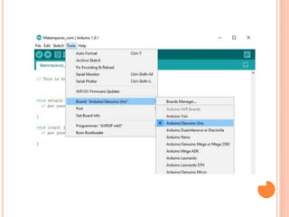
2. Key steps include downloading the Arduino IDE, selecting the board type in Tools, choosing the serial port, and uploading a basic blink program to test that the board is connected properly.
3. The document also provides an overview of programming concepts for Arduino like using variables, constants, and the setup and loop functions.