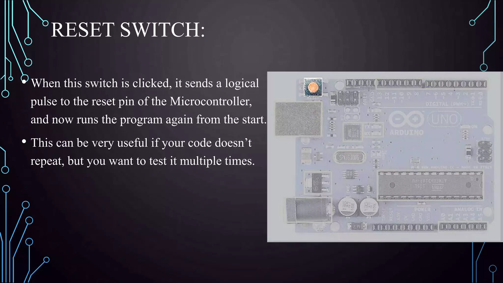
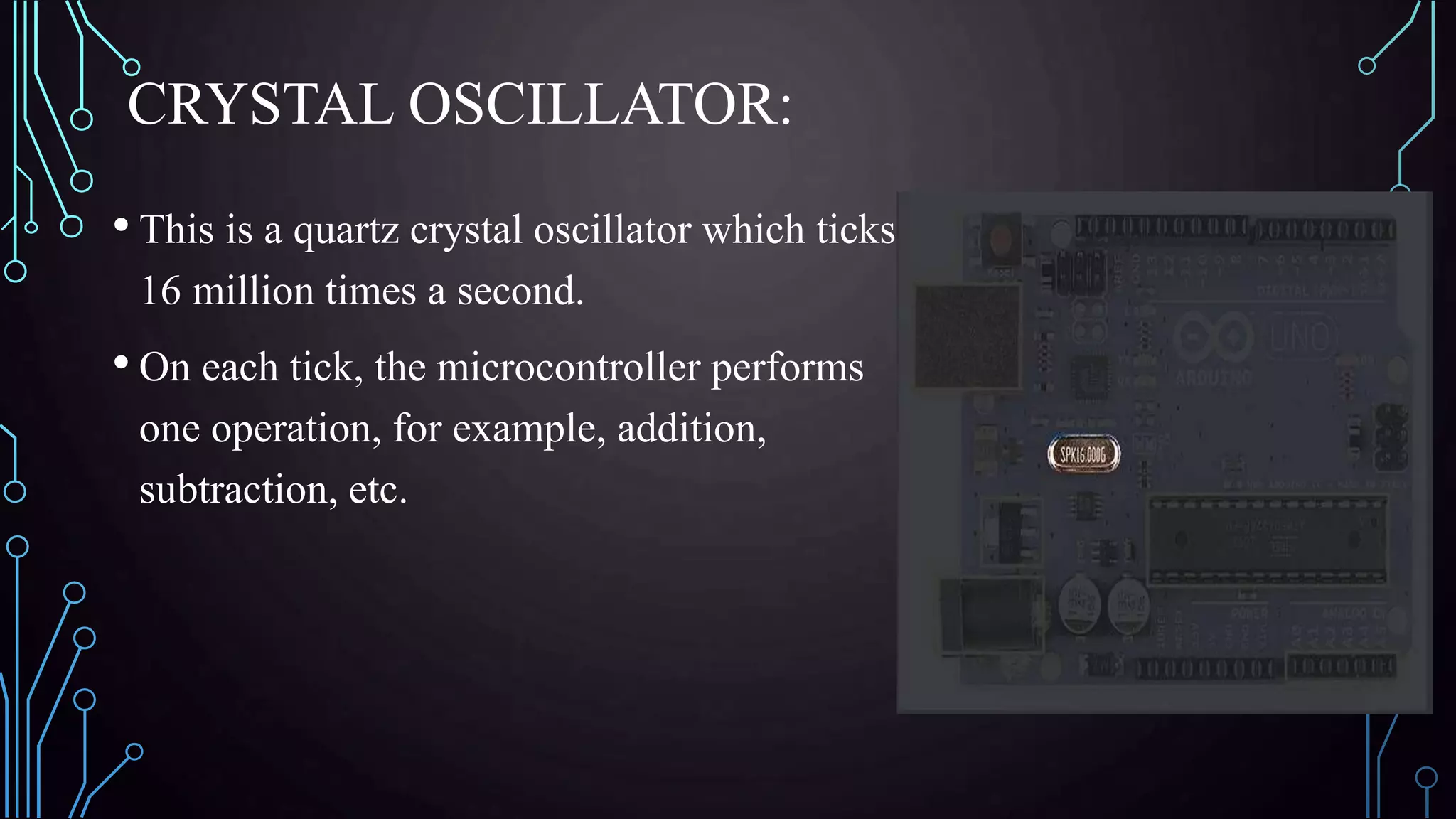
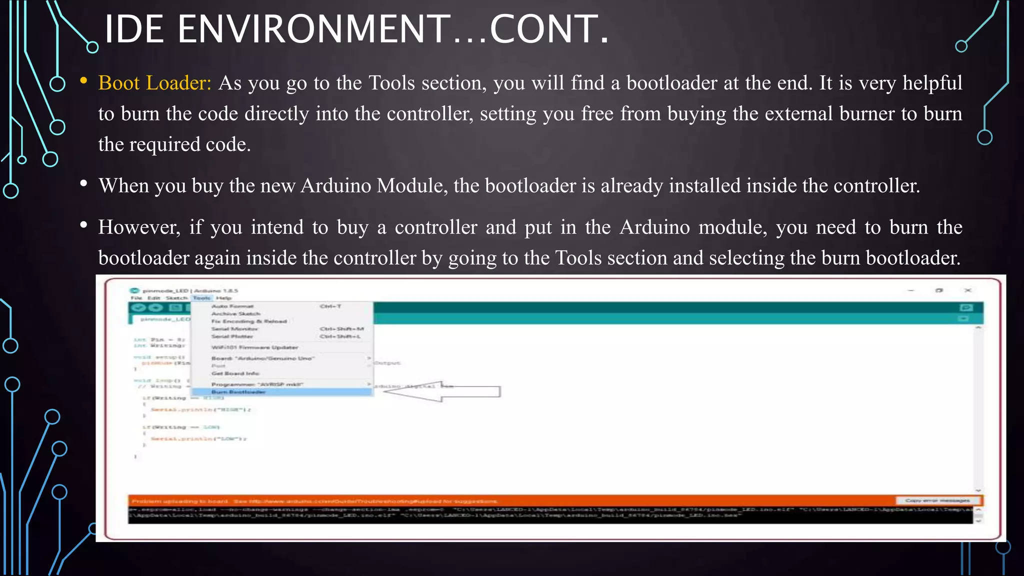
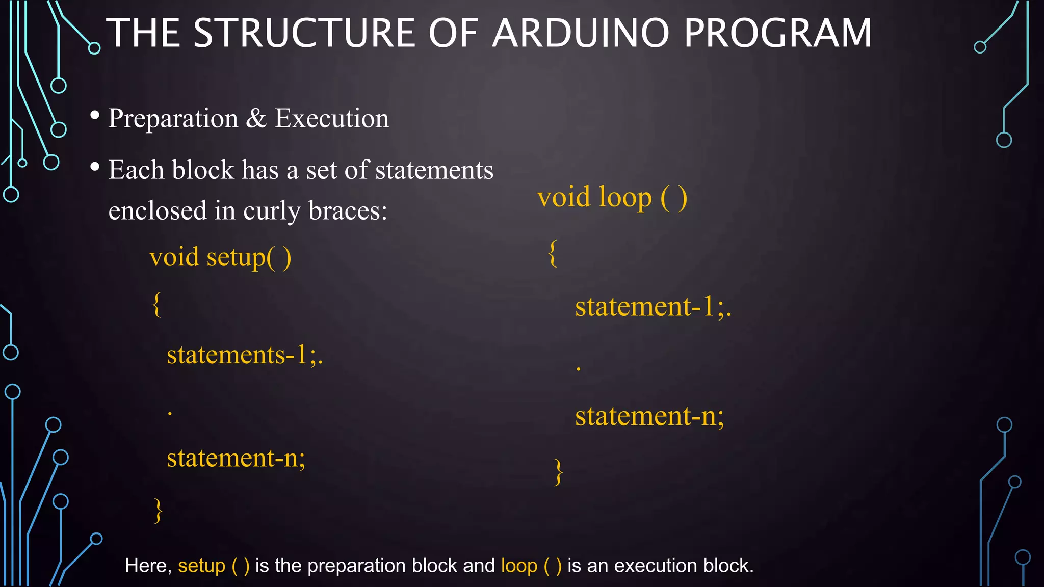
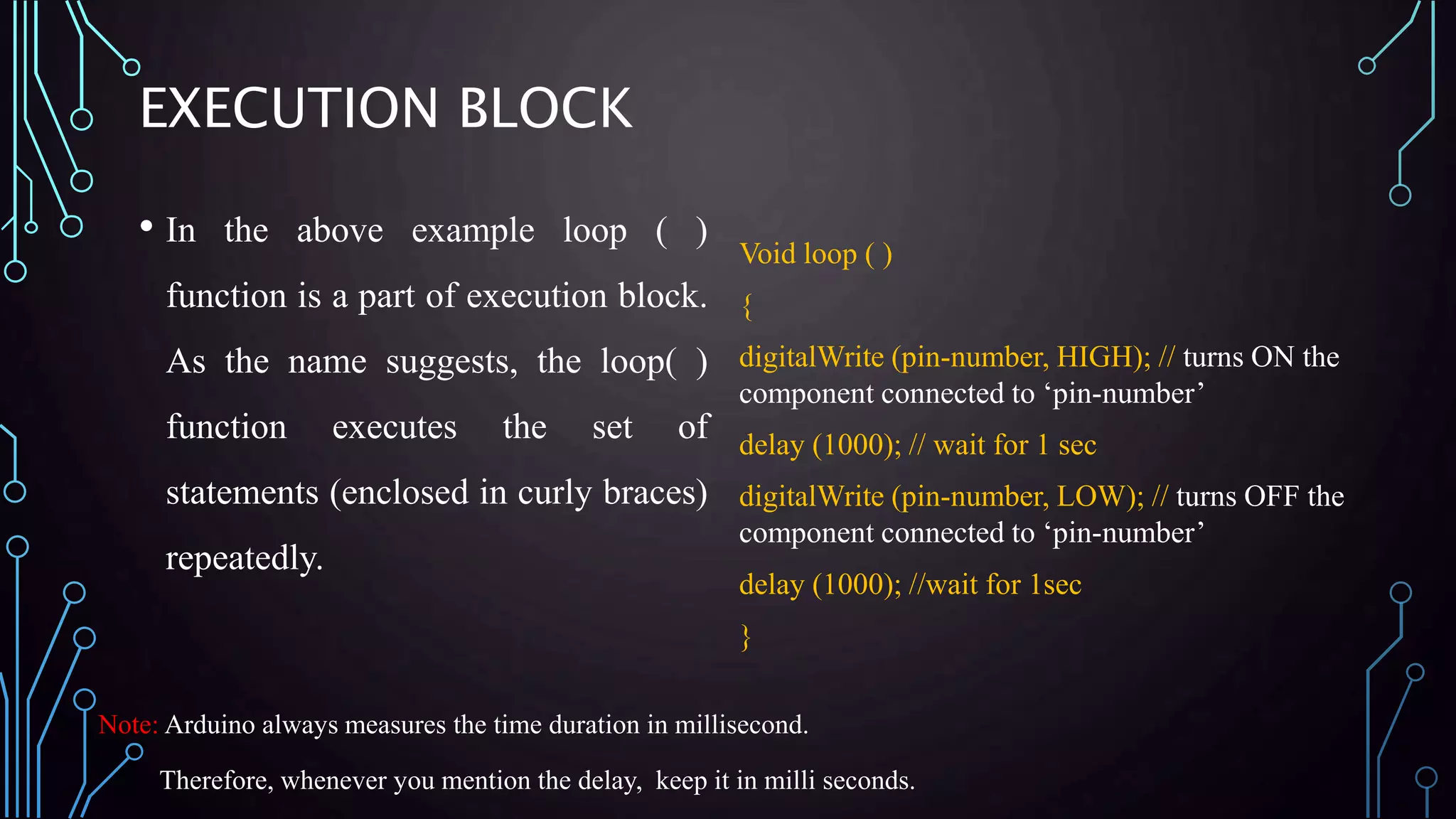
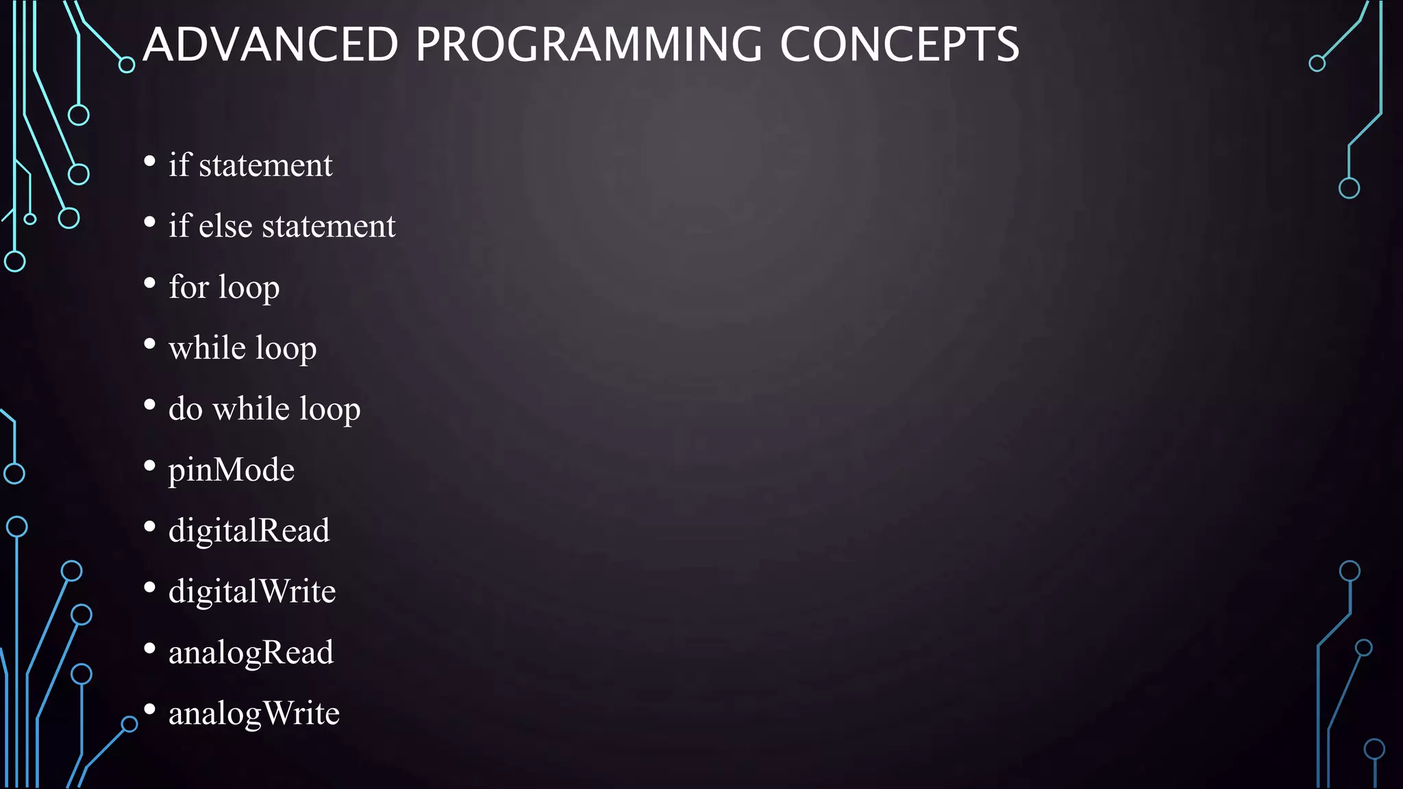
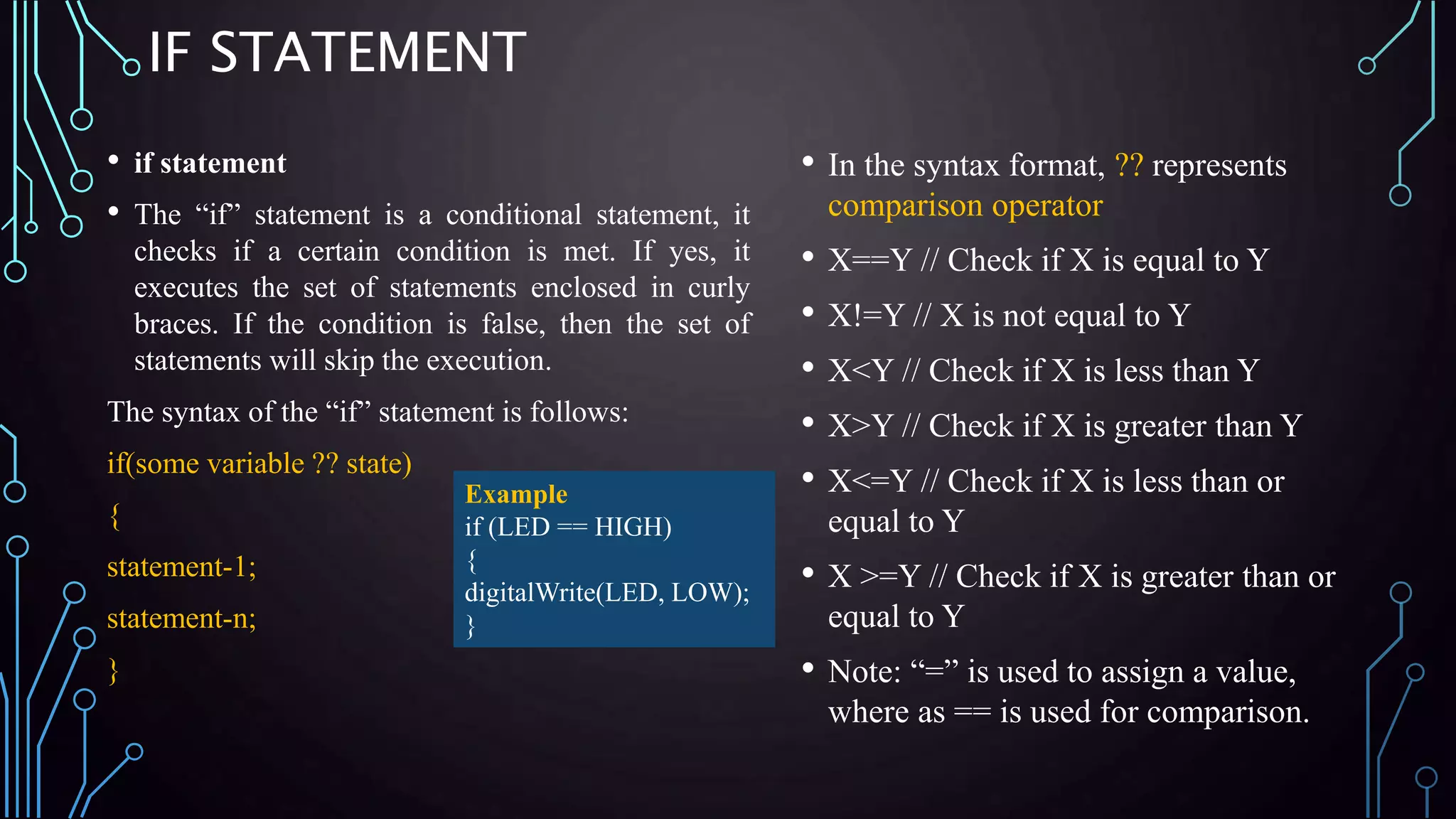
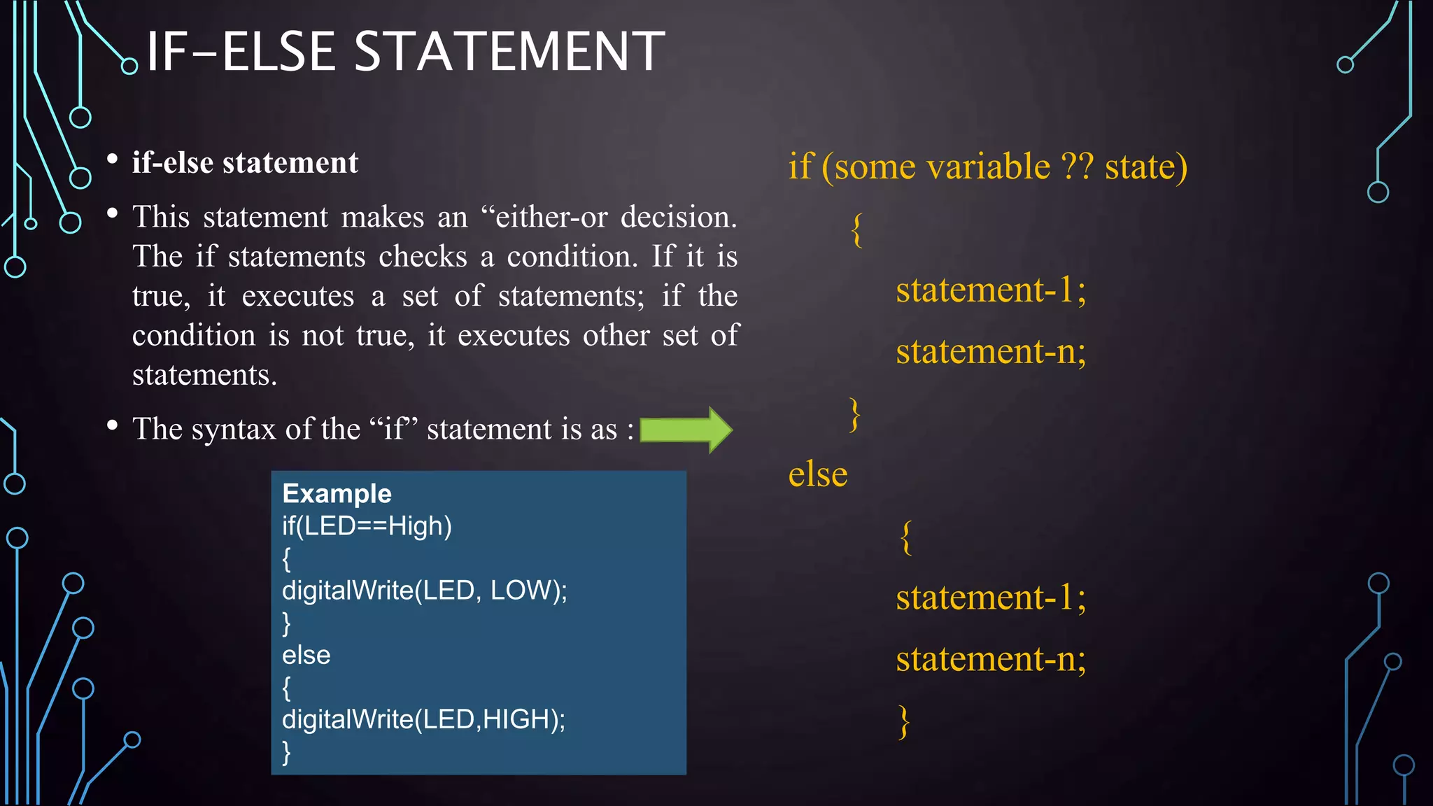
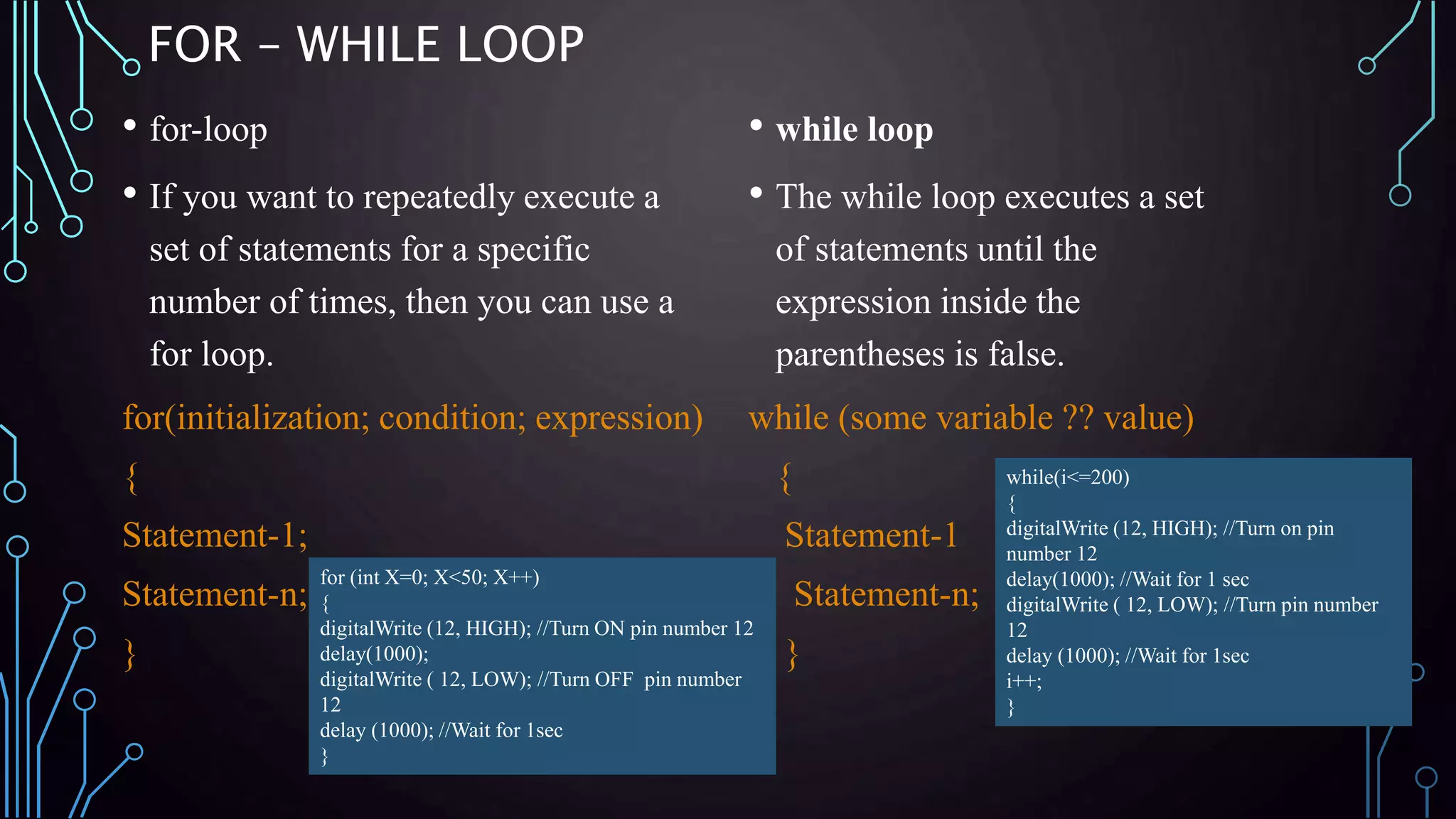
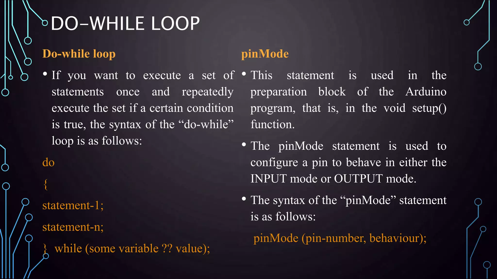
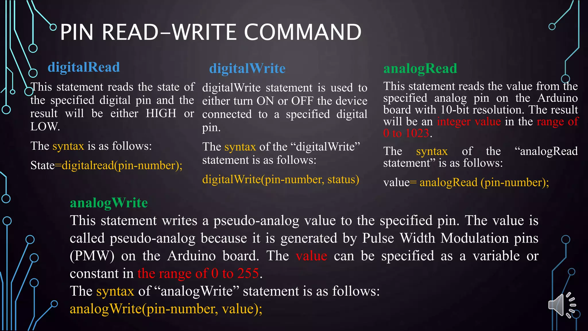
SlideShare a Scribd company logo
ONBOARD COMPONENTS DESCRIPTION, IDE
AND
PROGRAMMING SYNTAX
ARDUINO
By: Pawan Dubey
Research Mentor
Accendere Knowledge Management systems
WHAT IS ARDUINO ?
• Arduino is a microcontroller-based open source electronic prototyping board which
can be programmed with an easy-to-use Arduino IDE.
The major components of it are:
1. USB connector
2. Power port
3. Microcontroller
4. Analog input pins
5. Digital pins
6. Reset switch
7. Crystal oscillator
8. USB interface chip
9. TX RX LEDs
USB CONNECTOR
• This is a printer USB port used to load a program from the Arduino
IDE onto the Arduino board. The board can also be powered through
this port.
POWER PORT:
• The Arduino board can be powered through an AC-to-DC adapter or a battery. The
power source can be connected by plugging in a 2.1mm center-positive plug into the
power jack of the board.
• The Arduino UNO board operates at a voltage of 5 volts, but it can withstand a
maximum voltage of 20 volts.
MICROCONTROLLER:
• The most prominent black rectangular chip with 28 pins.
• The microcontroller used on the UNO board is Atmega328P by Atmel.
• Flash memory of 32KB: The program loaded from Arduino IDE
is stored here.
• RAM of 2KB: This is a runtime memory.
• CPU: It controls everything that goes on within the device.
It fetches the program instructions from flash memory, and runs them
with the help of RAM.
• Electrically Erasable Programmable Read Only Memory
(EEPROM) of 1KB. This is a type of nonvolatile memory, and it keeps the
data even after device restart and reset.
Atmega328P is pre-programmed with bootloader. This allows you to directly upload a new Arduino
program into the device, without using any external hardware programmer, making the Arduino
UNO board easy to use.
ANALOG INPUT PINS:
• The Arduino UNO board has 6 analog input pins, labeled “Analog 0 to 5.”
• These pins can read the signal from an analog sensor like a temperature sensor and convert it into a
digital value so that the system understands.
• These pins just measure voltage and not the current because they have very high internal resistance.
Hence, only a small amount of current flows through these pins.
• Although these pins are labeled analog and are analog input by default, these pins can also be used for
digital input or output.
DIGITAL PINS:
• You can find these pins labeled “Digital 0 to 13.” These
pins can be used as either input or output pins. When used
as output, these pins act as a power supply source for the
components connected to them. When used as input pins,
they read the signals from the component connected to
them.
• When digital pins are used as output pins, they supply 40
milliamps of current at 5 volts, which is more than
enough to light an LED.
• Some of the digital pins are labeled with tilde (~) symbol
next to the pin numbers (pin numbers 3, 5, 6, 9, 10, and
11). These pins act as normal digital pins but can also be
used for Pulse-Width Modulation (PWM), which
simulates analog output like fading an LED in and out.
RESET SWITCH:
• When this switch is clicked, it sends a logical
pulse to the reset pin of the Microcontroller,
and now runs the program again from the start.
• This can be very useful if your code doesn’t
repeat, but you want to test it multiple times.
CRYSTAL OSCILLATOR:
• This is a quartz crystal oscillator which ticks
16 million times a second.
• On each tick, the microcontroller performs
one operation, for example, addition,
subtraction, etc.
TX – RX LEDS:
• TX stands for transmit, and RX for receive.
• These are indicator LEDs which blink
whenever the UNO board is transmitting or
receiving data.
• Now that you have explored the Arduino
UNO board, you have started your journey
toward building your first IoT prototype.
• In the next article, we will discuss Arduino
programming and do a few experiments
with Arduino and LEDs.
ARDUINO IDE
PART – II
ARDUINO INTEGRATED DEVELOPMENT
ENVIRONMENT (IDE)
1. Arduino programs are written in the Arduino Integrated Development
Environment (IDE).
2. Arduino IDE is a special software running on your system that allows
you to write sketches (synonym for program in Arduino language) for
different Arduino boards.
3. The Arduino programming language is based on a very simple hardware
programming language called processing, which is similar to the C
language.
4. After the sketch is written in the Arduino IDE, it should be uploaded on
the Arduino board for execution.
IDE ENVIRONMENT
1.An official software introduced by
Arduino.cc, that is mainly used for
1. Writing,
2. Compiling and
3. Uploading the code in the Arduino
Device.
2.Almost all Arduino modules are
compatible with this software that is an
open source and is readily available to
install and start compiling the code on the
go.
IDE ENVIRONMENT…CONT.
HOW TO DOWNLOAD THE SOFTWARE
1. You can download the Software from Arduino main website.
2. If you aim to download Windows app version, make sure you have
Windows 8.1 or Windows 10, as app version is not compatible with
Windows 7 or older version of this operating system.
IDE
ENVIRONMENT…CONT.
• File – You can open a new window for writing
the code or open an existing one.
• Edit – Used for copying and pasting the code
with further modification for font
• Sketch – For compiling and programming
• Tools – Mainly used for testing projects. The
Programmer section in this panel is used for
burning a bootloader to the new
microcontroller.
• Help – In case you are feeling skeptical about
software, complete help is available from
getting started to troubleshooting.
IDE
ENVIRONMENT…CONT.
• The check mark appearing in the circular
button is used to verify the code. Click this
once you have written your code.
• The arrow key will upload and transfer the
required code to the Arduino board.
• The dotted paper is used for creating a new
file.
• The upward arrow is reserved for opening
an existing Arduino project.
• The downward arrow is used to save the
current running code.
• The button appearing on the top right
corner is a Serial Monitor (Ctrl+Shift+M) –
A separate pop-up window that acts as an
independent terminal and plays a vital role
for sending and receiving the Serial Data.
IDE
ENVIRONMENT…CONT.
• The Serial Monitor will actually help to debug
the written Sketches where you can get a hold
of how your program is operating.
• Your Arduino Module should be connected to
your computer by USB cable in order to
activate the Serial Monitor.
• You need to select the baud rate of the Arduino
Board you are using right now.
• The baud rate may be different for different
Arduino which can be verified by
specifications.
IDE
ENVIRONMENT…CONT.
• The main screen below the Menu bar is known as a simple text editor used for writing the
required code.
• The bottom of the main screen is described as an Output Pane that mainly highlights the
compilation status of the running code: the memory used by the code, and errors occurred
in the program.
• You need to fix those errors before you intend to upload the hex file into your Arduino
Module.
IDE
ENVIRONMENT…CONT.
•Libraries are very useful for adding the extra functionality into the Arduino Module.
There is a list of libraries you can add by clicking the Sketch button in the menu bar and
going to Include Library..
• Most of the libraries are preinstalled and come with the Arduino software. However, you
can also download them from the external sources.
IDE
ENVIRONMENT…CONT.• Selection of the Arduino Board
IDE
ENVIRONMENT…CONT.
• Selection of the communication port:
• COM1, COM2, COM4, COM5, COM7 or higher
are reserved for the serial and USB board.
• You can look for the USB serial device in the
ports section of the Windows Device Manager.
• After correct selection of both Board and Serial
Port, click the verify and then upload button
appearing in the upper left corner of the six button
section or you can go to the Sketch section and
press verify/compile and then upload.
• After correct selection of both Board and Serial Port, click the verify and then
upload button appearing in the upper left corner of the six button section or you can
go to the Sketch section and press verify/compile and then upload.
• The sketch is written in the text editor and is then saved with the file extension .ino.
• It is important to note that the recent Arduino Modules will reset automatically as
you compile and press the upload button the IDE software, however, older version
may require the physical reset on the board.
• Once you upload the code, TX and RX LEDs will blink on the board, indicating
the desired program is running successfully.
• The amazing thing about this software is that no prior arrangement or bulk of
mess is required to install this software, you will be writing your first program
within 2 minutes after the installation of the IDE environment.
IDE ENVIRONMENT…CONT.
• Boot Loader: As you go to the Tools section, you will find a bootloader at the end. It is very helpful
to burn the code directly into the controller, setting you free from buying the external burner to burn
the required code.
• When you buy the new Arduino Module, the bootloader is already installed inside the controller.
• However, if you intend to buy a controller and put in the Arduino module, you need to burn the
bootloader again inside the controller by going to the Tools section and selecting the burn bootloader.
PART – III
ARDUINO PROGRAMMING
THE STRUCTURE OF ARDUINO PROGRAM
• Preparation & Execution
• Each block has a set of statements
enclosed in curly braces:
void setup( )
{
statements-1;.
.
statement-n;
}
void loop ( )
{
statement-1;.
.
statement-n;
}
Here, setup ( ) is the preparation block and loop ( ) is an execution block.
THE SET-UP
• The setup function is the first to execute
when the program is executed, and this
function is called only once.
• The setup function is used to initialize the
pin modes and start serial communication.
• This function has to be included even if
there are no statements to execute.
• After the setup ( ) function is executed,
the execution block runs next.
void setup ( )
{
pinMode (pin-number, OUTPUT); // set the ‘pin-
number’ as output
pinMode (pin-number, INPUT); // set the ‘pin-number’
as output
}
EXECUTION BLOCK
• In the above example loop ( )
function is a part of execution block.
As the name suggests, the loop( )
function executes the set of
statements (enclosed in curly braces)
repeatedly.
Void loop ( )
{
digitalWrite (pin-number, HIGH); // turns ON the
component connected to ‘pin-number’
delay (1000); // wait for 1 sec
digitalWrite (pin-number, LOW); // turns OFF the
component connected to ‘pin-number’
delay (1000); //wait for 1sec
}
Note: Arduino always measures the time duration in millisecond.
Therefore, whenever you mention the delay, keep it in milli seconds.
EXAMPLE : LED BLINKING
• Steps in BUILDING A BREADBOARD
CONNECTION:
• Step-1: Connect the Arduino to the Windows
/ Mac / Linux system via a USB cable
• Step-2: Connect the 13th digital pin of
Arduino to the positive power rail of the
breadboard and GND to the negative
• Step-3: Connect the positive power rail to
the terminal strip via a 1K ohm resistor
• Step-4: Fix the LED to the ports below the
resistor connection in the terminal strip
• Step-5: Close the circuit by connecting the
cathode (the short chord) of the LED to the
negative power strip of the breadboard
PROGRAM: LED BLINKING
void setup ( )
{
pinMode (LED, OUTPUT); //Declaring pin 13 as output pin
}
void loop( ) // The loop function runs again and again
{
digitalWrite (LED, HIGH); //Turn ON the LED
delay(1000); //Wait for 1sec
digitalRead (LED, LOW); // Turn off the LED
delay(1000); // Wait for 1sec
}
EXERCISE : WRITE A PROGRAM OF LED FADING
ADVANCED PROGRAMMING CONCEPTS
• if statement
• if else statement
• for loop
• while loop
• do while loop
• pinMode
• digitalRead
• digitalWrite
• analogRead
• analogWrite
IF STATEMENT
• if statement
• The “if” statement is a conditional statement, it
checks if a certain condition is met. If yes, it
executes the set of statements enclosed in curly
braces. If the condition is false, then the set of
statements will skip the execution.
The syntax of the “if” statement is follows:
if(some variable ?? state)
{
statement-1;
statement-n;
}
• In the syntax format, ?? represents
comparison operator
• X==Y // Check if X is equal to Y
• X!=Y // X is not equal to Y
• X<Y // Check if X is less than Y
• X>Y // Check if X is greater than Y
• X<=Y // Check if X is less than or
equal to Y
• X >=Y // Check if X is greater than or
equal to Y
• Note: “=” is used to assign a value,
where as == is used for comparison.
Example
if (LED == HIGH)
{
digitalWrite(LED, LOW);
}
IF-ELSE STATEMENT
• if-else statement
• This statement makes an “either-or decision.
The if statements checks a condition. If it is
true, it executes a set of statements; if the
condition is not true, it executes other set of
statements.
• The syntax of the “if” statement is as :
if (some variable ?? state)
{
statement-1;
statement-n;
}
else
{
statement-1;
statement-n;
}
Example
if(LED==High)
{
digitalWrite(LED, LOW);
}
else
{
digitalWrite(LED,HIGH);
}
FOR – WHILE LOOP
• while loop
• The while loop executes a set
of statements until the
expression inside the
parentheses is false.
while (some variable ?? value)
{
Statement-1
Statement-n;
}
• for-loop
• If you want to repeatedly execute a
set of statements for a specific
number of times, then you can use a
for loop.
for(initialization; condition; expression)
{
Statement-1;
Statement-n;
}
while(i<=200)
{
digitalWrite (12, HIGH); //Turn on pin
number 12
delay(1000); //Wait for 1 sec
digitalWrite ( 12, LOW); //Turn pin number
12
delay (1000); //Wait for 1sec
i++;
}
for (int X=0; X<50; X++)
{
digitalWrite (12, HIGH); //Turn ON pin number 12
delay(1000);
digitalWrite ( 12, LOW); //Turn OFF pin number
12
delay (1000); //Wait for 1sec
}
DO-WHILE LOOP
Do-while loop
• If you want to execute a set of
statements once and repeatedly
execute the set if a certain condition
is true, the syntax of the “do-while”
loop is as follows:
do
{
statement-1;
statement-n;
} while (some variable ?? value);
pinMode
• This statement is used in the
preparation block of the Arduino
program, that is, in the void setup()
function.
• The pinMode statement is used to
configure a pin to behave in either the
INPUT mode or OUTPUT mode.
• The syntax of the “pinMode” statement
is as follows:
pinMode (pin-number, behaviour);
PIN READ-WRITE COMMAND
This statement reads the state of
the specified digital pin and the
result will be either HIGH or
LOW.
The syntax is as follows:
State=digitalread(pin-number);
digitalRead
digitalWrite statement is used to
either turn ON or OFF the device
connected to a specified digital
pin.
The syntax of the “digitalWrite”
statement is as follows:
digitalWrite(pin-number, status)
This statement reads the value from the
specified analog pin on the Arduino
board with 10-bit resolution. The result
will be an integer value in the range of
0 to 1023.
The syntax of the “analogRead
statement” is as follows:
value= analogRead (pin-number);
digitalWrite analogRead
analogWrite
This statement writes a pseudo-analog value to the specified pin. The value is
called pseudo-analog because it is generated by Pulse Width Modulation pins
(PMW) on the Arduino board. The value can be specified as a variable or
constant in the range of 0 to 255.
The syntax of “analogWrite” statement is as follows:
analogWrite(pin-number, value);

More Related Content

What's hot

Arduino uno
Arduino unoArduino uno
Arduino uno
creatjet3d labs
 
Arduino
ArduinoArduino
Arduino
Jerin John
 
Arduino for beginners- Introduction to Arduino (presentation) - codewithgauri
Arduino for beginners- Introduction to Arduino (presentation) - codewithgauriArduino for beginners- Introduction to Arduino (presentation) - codewithgauri
Arduino for beginners- Introduction to Arduino (presentation) - codewithgauri
Gaurav Pandey
 
Introduction to Arduino
Introduction to ArduinoIntroduction to Arduino
Introduction to Arduino
Omer Kilic
 
8051 block diagram
8051 block diagram8051 block diagram
8051 block diagram
DominicHendry
 
Arduino Workshop
Arduino WorkshopArduino Workshop
Arduino Workshop
atuline
 
Lesson sample introduction to arduino
Lesson sample   introduction to arduinoLesson sample   introduction to arduino
Lesson sample introduction to arduino
Betsy Eng
 
Introduction to Arduino
Introduction to ArduinoIntroduction to Arduino
Introduction to Arduino
Richard Rixham
 
Introduction to arduino
Introduction to arduinoIntroduction to arduino
Introduction to arduinoAhmed Sakr
 
Embedded c
Embedded cEmbedded c
Embedded c
Ami Prakash
 
Basics of arduino uno
Basics of arduino unoBasics of arduino uno
Basics of arduino uno
Rahat Sood
 
Introduction to Arduino Hardware and Programming
Introduction to Arduino Hardware and ProgrammingIntroduction to Arduino Hardware and Programming
Introduction to Arduino Hardware and Programming
Emmanuel Obot
 
What is Arduino ?
What is Arduino ?What is Arduino ?
What is Arduino ?
Niket Chandrawanshi
 
Arduino IDE
Arduino IDE Arduino IDE
Arduino IDE
Mrunal Deshkar
 
Arduino
ArduinoArduino
Arduino
vipin7vj
 
Introduction to Arduino
Introduction to ArduinoIntroduction to Arduino
Introduction to Arduino
Yong Heui Cho
 
Arduino course
Arduino courseArduino course
Arduino course
Ahmed Shelbaya
 
Blinking a Single LED
Blinking a Single LEDBlinking a Single LED
Blinking a Single LED
Rihab Rahman
 
Introduction to arduino
Introduction to arduinoIntroduction to arduino
Introduction to arduino
Jawaher Abdulwahab Fadhil
 

What's hot (20)

Arduino uno
Arduino unoArduino uno
Arduino uno
 
Arduino
ArduinoArduino
Arduino
 
Arduino for beginners- Introduction to Arduino (presentation) - codewithgauri
Arduino for beginners- Introduction to Arduino (presentation) - codewithgauriArduino for beginners- Introduction to Arduino (presentation) - codewithgauri
Arduino for beginners- Introduction to Arduino (presentation) - codewithgauri
 
Introduction to Arduino
Introduction to ArduinoIntroduction to Arduino
Introduction to Arduino
 
8051 block diagram
8051 block diagram8051 block diagram
8051 block diagram
 
Arduino Workshop
Arduino WorkshopArduino Workshop
Arduino Workshop
 
Arduino Programming Basic
Arduino Programming BasicArduino Programming Basic
Arduino Programming Basic
 
Lesson sample introduction to arduino
Lesson sample   introduction to arduinoLesson sample   introduction to arduino
Lesson sample introduction to arduino
 
Introduction to Arduino
Introduction to ArduinoIntroduction to Arduino
Introduction to Arduino
 
Introduction to arduino
Introduction to arduinoIntroduction to arduino
Introduction to arduino
 
Embedded c
Embedded cEmbedded c
Embedded c
 
Basics of arduino uno
Basics of arduino unoBasics of arduino uno
Basics of arduino uno
 
Introduction to Arduino Hardware and Programming
Introduction to Arduino Hardware and ProgrammingIntroduction to Arduino Hardware and Programming
Introduction to Arduino Hardware and Programming
 
What is Arduino ?
What is Arduino ?What is Arduino ?
What is Arduino ?
 
Arduino IDE
Arduino IDE Arduino IDE
Arduino IDE
 
Arduino
ArduinoArduino
Arduino
 
Introduction to Arduino
Introduction to ArduinoIntroduction to Arduino
Introduction to Arduino
 
Arduino course
Arduino courseArduino course
Arduino course
 
Blinking a Single LED
Blinking a Single LEDBlinking a Single LED
Blinking a Single LED
 
Introduction to arduino
Introduction to arduinoIntroduction to arduino
Introduction to arduino
 

Similar to Arduino: On-board components description, IDE and Programming

Embedded L1_notes_unit2_architecture.pptx
Embedded L1_notes_unit2_architecture.pptxEmbedded L1_notes_unit2_architecture.pptx
Embedded L1_notes_unit2_architecture.pptx
aartis110
 
Indroduction arduino
Indroduction arduinoIndroduction arduino
Indroduction arduino
ThingerbitsElectroni
 
Indroduction the arduino
Indroduction the arduinoIndroduction the arduino
Indroduction the arduino
Hasarinda Manjula
 
Getting Started With Arduino_Tutorial
Getting Started With Arduino_TutorialGetting Started With Arduino_Tutorial
Getting Started With Arduino_Tutorial
NYCCTfab
 
IOT ARDUINO UNO.pptx
IOT ARDUINO UNO.pptxIOT ARDUINO UNO.pptx
IOT ARDUINO UNO.pptx
SanaMateen7
 
Introduction to Arduino
Introduction to ArduinoIntroduction to Arduino
Introduction to Arduino
Damien Magoni
 
Arduino microcontroller ins and outs with pin diagram
Arduino microcontroller ins and outs with pin diagramArduino microcontroller ins and outs with pin diagram
Arduino microcontroller ins and outs with pin diagram
ArifatunNesa
 
arduino uno.pptx
arduino uno.pptxarduino uno.pptx
arduino uno.pptx
NeeladriBijayMisra
 
Arduino Family
Arduino FamilyArduino Family
Arduino Family
mahalakshmimalini
 
Internet of Things Unit 3 notes-Design and Development and Arduino.pptx
Internet of Things Unit 3 notes-Design and Development and Arduino.pptxInternet of Things Unit 3 notes-Design and Development and Arduino.pptx
Internet of Things Unit 3 notes-Design and Development and Arduino.pptx
Dinola2
 
Introduction to Arduino.pptx
Introduction to Arduino.pptxIntroduction to Arduino.pptx
Introduction to Arduino.pptx
Akshat Bijronia
 
Lecture 7
Lecture 7Lecture 7
Lecture 7
vishal choudhary
 
Intro arduino
Intro arduinoIntro arduino
Intro arduino
MaLcom MooNwalker
 
Arduino01.pptx
Arduino01.pptxArduino01.pptx
Arduino01.pptx
kaustubhshedbalkar1
 
WORKING PRINCIPLE OF ARDUINO AND USING IT AS A TOOL FOR STUDY AND RESEARCH
WORKING PRINCIPLE OF ARDUINO AND USING IT AS A TOOL FOR STUDY AND RESEARCHWORKING PRINCIPLE OF ARDUINO AND USING IT AS A TOOL FOR STUDY AND RESEARCH
WORKING PRINCIPLE OF ARDUINO AND USING IT AS A TOOL FOR STUDY AND RESEARCH
ijdpsjournal
 
Arduino intro.pptx
Arduino intro.pptxArduino intro.pptx
Arduino intro.pptx
AlexRiv4
 
The IoT Academy IoT training Arduino Part 1 basics
The IoT Academy IoT training Arduino Part 1 basicsThe IoT Academy IoT training Arduino Part 1 basics
The IoT Academy IoT training Arduino Part 1 basics
The IOT Academy
 
Embedded system programming using Arduino microcontroller
Embedded system programming using Arduino microcontrollerEmbedded system programming using Arduino microcontroller
Embedded system programming using Arduino microcontroller
Arun Kumar
 
1.Arduino Ecosystem.pptx
1.Arduino Ecosystem.pptx1.Arduino Ecosystem.pptx
1.Arduino Ecosystem.pptx
Mohamed Essam
 
Arduino uno
Arduino unoArduino uno

Similar to Arduino: On-board components description, IDE and Programming (20)

Embedded L1_notes_unit2_architecture.pptx
Embedded L1_notes_unit2_architecture.pptxEmbedded L1_notes_unit2_architecture.pptx
Embedded L1_notes_unit2_architecture.pptx
 
Indroduction arduino
Indroduction arduinoIndroduction arduino
Indroduction arduino
 
Indroduction the arduino
Indroduction the arduinoIndroduction the arduino
Indroduction the arduino
 
Getting Started With Arduino_Tutorial
Getting Started With Arduino_TutorialGetting Started With Arduino_Tutorial
Getting Started With Arduino_Tutorial
 
IOT ARDUINO UNO.pptx
IOT ARDUINO UNO.pptxIOT ARDUINO UNO.pptx
IOT ARDUINO UNO.pptx
 
Introduction to Arduino
Introduction to ArduinoIntroduction to Arduino
Introduction to Arduino
 
Arduino microcontroller ins and outs with pin diagram
Arduino microcontroller ins and outs with pin diagramArduino microcontroller ins and outs with pin diagram
Arduino microcontroller ins and outs with pin diagram
 
arduino uno.pptx
arduino uno.pptxarduino uno.pptx
arduino uno.pptx
 
Arduino Family
Arduino FamilyArduino Family
Arduino Family
 
Internet of Things Unit 3 notes-Design and Development and Arduino.pptx
Internet of Things Unit 3 notes-Design and Development and Arduino.pptxInternet of Things Unit 3 notes-Design and Development and Arduino.pptx
Internet of Things Unit 3 notes-Design and Development and Arduino.pptx
 
Introduction to Arduino.pptx
Introduction to Arduino.pptxIntroduction to Arduino.pptx
Introduction to Arduino.pptx
 
Lecture 7
Lecture 7Lecture 7
Lecture 7
 
Intro arduino
Intro arduinoIntro arduino
Intro arduino
 
Arduino01.pptx
Arduino01.pptxArduino01.pptx
Arduino01.pptx
 
WORKING PRINCIPLE OF ARDUINO AND USING IT AS A TOOL FOR STUDY AND RESEARCH
WORKING PRINCIPLE OF ARDUINO AND USING IT AS A TOOL FOR STUDY AND RESEARCHWORKING PRINCIPLE OF ARDUINO AND USING IT AS A TOOL FOR STUDY AND RESEARCH
WORKING PRINCIPLE OF ARDUINO AND USING IT AS A TOOL FOR STUDY AND RESEARCH
 
Arduino intro.pptx
Arduino intro.pptxArduino intro.pptx
Arduino intro.pptx
 
The IoT Academy IoT training Arduino Part 1 basics
The IoT Academy IoT training Arduino Part 1 basicsThe IoT Academy IoT training Arduino Part 1 basics
The IoT Academy IoT training Arduino Part 1 basics
 
Embedded system programming using Arduino microcontroller
Embedded system programming using Arduino microcontrollerEmbedded system programming using Arduino microcontroller
Embedded system programming using Arduino microcontroller
 
1.Arduino Ecosystem.pptx
1.Arduino Ecosystem.pptx1.Arduino Ecosystem.pptx
1.Arduino Ecosystem.pptx
 
Arduino uno
Arduino unoArduino uno
Arduino uno
 

Recently uploaded

H.Seo, ICLR 2024, MLILAB, KAIST AI.pdf
H.Seo,  ICLR 2024, MLILAB,  KAIST AI.pdfH.Seo,  ICLR 2024, MLILAB,  KAIST AI.pdf
H.Seo, ICLR 2024, MLILAB, KAIST AI.pdf
MLILAB
 
Top 10 Oil and Gas Projects in Saudi Arabia 2024.pdf
Top 10 Oil and Gas Projects in Saudi Arabia 2024.pdfTop 10 Oil and Gas Projects in Saudi Arabia 2024.pdf
Top 10 Oil and Gas Projects in Saudi Arabia 2024.pdf
Teleport Manpower Consultant
 
Pile Foundation by Venkatesh Taduvai (Sub Geotechnical Engineering II)-conver...
Pile Foundation by Venkatesh Taduvai (Sub Geotechnical Engineering II)-conver...Pile Foundation by Venkatesh Taduvai (Sub Geotechnical Engineering II)-conver...
Pile Foundation by Venkatesh Taduvai (Sub Geotechnical Engineering II)-conver...
AJAYKUMARPUND1
 
WATER CRISIS and its solutions-pptx 1234
WATER CRISIS and its solutions-pptx 1234WATER CRISIS and its solutions-pptx 1234
WATER CRISIS and its solutions-pptx 1234
AafreenAbuthahir2
 
ethical hacking in wireless-hacking1.ppt
ethical hacking in wireless-hacking1.pptethical hacking in wireless-hacking1.ppt
ethical hacking in wireless-hacking1.ppt
Jayaprasanna4
 
J.Yang, ICLR 2024, MLILAB, KAIST AI.pdf
J.Yang,  ICLR 2024, MLILAB, KAIST AI.pdfJ.Yang,  ICLR 2024, MLILAB, KAIST AI.pdf
J.Yang, ICLR 2024, MLILAB, KAIST AI.pdf
MLILAB
 
Automobile Management System Project Report.pdf
Automobile Management System Project Report.pdfAutomobile Management System Project Report.pdf
Automobile Management System Project Report.pdf
Kamal Acharya
 
road safety engineering r s e unit 3.pdf
road safety engineering  r s e unit 3.pdfroad safety engineering  r s e unit 3.pdf
road safety engineering r s e unit 3.pdf
VENKATESHvenky89705
 
Architectural Portfolio Sean Lockwood
Architectural Portfolio Sean LockwoodArchitectural Portfolio Sean Lockwood
Architectural Portfolio Sean Lockwood
seandesed
 
一比一原版(SFU毕业证)西蒙菲莎大学毕业证成绩单如何办理
一比一原版(SFU毕业证)西蒙菲莎大学毕业证成绩单如何办理一比一原版(SFU毕业证)西蒙菲莎大学毕业证成绩单如何办理
一比一原版(SFU毕业证)西蒙菲莎大学毕业证成绩单如何办理
bakpo1
 
Event Management System Vb Net Project Report.pdf
Event Management System Vb Net  Project Report.pdfEvent Management System Vb Net  Project Report.pdf
Event Management System Vb Net Project Report.pdf
Kamal Acharya
 
Forklift Classes Overview by Intella Parts
Forklift Classes Overview by Intella PartsForklift Classes Overview by Intella Parts
Forklift Classes Overview by Intella Parts
Intella Parts
 
Cosmetic shop management system project report.pdf
Cosmetic shop management system project report.pdfCosmetic shop management system project report.pdf
Cosmetic shop management system project report.pdf
Kamal Acharya
 
Gen AI Study Jams _ For the GDSC Leads in India.pdf
Gen AI Study Jams _ For the GDSC Leads in India.pdfGen AI Study Jams _ For the GDSC Leads in India.pdf
Gen AI Study Jams _ For the GDSC Leads in India.pdf
gdsczhcet
 
Vaccine management system project report documentation..pdf
Vaccine management system project report documentation..pdfVaccine management system project report documentation..pdf
Vaccine management system project report documentation..pdf
Kamal Acharya
 
NO1 Uk best vashikaran specialist in delhi vashikaran baba near me online vas...
NO1 Uk best vashikaran specialist in delhi vashikaran baba near me online vas...NO1 Uk best vashikaran specialist in delhi vashikaran baba near me online vas...
NO1 Uk best vashikaran specialist in delhi vashikaran baba near me online vas...
Amil Baba Dawood bangali
 
Quality defects in TMT Bars, Possible causes and Potential Solutions.
Quality defects in TMT Bars, Possible causes and Potential Solutions.Quality defects in TMT Bars, Possible causes and Potential Solutions.
Quality defects in TMT Bars, Possible causes and Potential Solutions.
PrashantGoswami42
 
Planning Of Procurement o different goods and services
Planning Of Procurement o different goods and servicesPlanning Of Procurement o different goods and services
Planning Of Procurement o different goods and services
JoytuBarua2
 
Democratizing Fuzzing at Scale by Abhishek Arya
Democratizing Fuzzing at Scale by Abhishek AryaDemocratizing Fuzzing at Scale by Abhishek Arya
Democratizing Fuzzing at Scale by Abhishek Arya
abh.arya
 
ethical hacking-mobile hacking methods.ppt
ethical hacking-mobile hacking methods.pptethical hacking-mobile hacking methods.ppt
ethical hacking-mobile hacking methods.ppt
Jayaprasanna4
 

Recently uploaded (20)

H.Seo, ICLR 2024, MLILAB, KAIST AI.pdf
H.Seo,  ICLR 2024, MLILAB,  KAIST AI.pdfH.Seo,  ICLR 2024, MLILAB,  KAIST AI.pdf
H.Seo, ICLR 2024, MLILAB, KAIST AI.pdf
 
Top 10 Oil and Gas Projects in Saudi Arabia 2024.pdf
Top 10 Oil and Gas Projects in Saudi Arabia 2024.pdfTop 10 Oil and Gas Projects in Saudi Arabia 2024.pdf
Top 10 Oil and Gas Projects in Saudi Arabia 2024.pdf
 
Pile Foundation by Venkatesh Taduvai (Sub Geotechnical Engineering II)-conver...
Pile Foundation by Venkatesh Taduvai (Sub Geotechnical Engineering II)-conver...Pile Foundation by Venkatesh Taduvai (Sub Geotechnical Engineering II)-conver...
Pile Foundation by Venkatesh Taduvai (Sub Geotechnical Engineering II)-conver...
 
WATER CRISIS and its solutions-pptx 1234
WATER CRISIS and its solutions-pptx 1234WATER CRISIS and its solutions-pptx 1234
WATER CRISIS and its solutions-pptx 1234
 
ethical hacking in wireless-hacking1.ppt
ethical hacking in wireless-hacking1.pptethical hacking in wireless-hacking1.ppt
ethical hacking in wireless-hacking1.ppt
 
J.Yang, ICLR 2024, MLILAB, KAIST AI.pdf
J.Yang,  ICLR 2024, MLILAB, KAIST AI.pdfJ.Yang,  ICLR 2024, MLILAB, KAIST AI.pdf
J.Yang, ICLR 2024, MLILAB, KAIST AI.pdf
 
Automobile Management System Project Report.pdf
Automobile Management System Project Report.pdfAutomobile Management System Project Report.pdf
Automobile Management System Project Report.pdf
 
road safety engineering r s e unit 3.pdf
road safety engineering  r s e unit 3.pdfroad safety engineering  r s e unit 3.pdf
road safety engineering r s e unit 3.pdf
 
Architectural Portfolio Sean Lockwood
Architectural Portfolio Sean LockwoodArchitectural Portfolio Sean Lockwood
Architectural Portfolio Sean Lockwood
 
一比一原版(SFU毕业证)西蒙菲莎大学毕业证成绩单如何办理
一比一原版(SFU毕业证)西蒙菲莎大学毕业证成绩单如何办理一比一原版(SFU毕业证)西蒙菲莎大学毕业证成绩单如何办理
一比一原版(SFU毕业证)西蒙菲莎大学毕业证成绩单如何办理
 
Event Management System Vb Net Project Report.pdf
Event Management System Vb Net  Project Report.pdfEvent Management System Vb Net  Project Report.pdf
Event Management System Vb Net Project Report.pdf
 
Forklift Classes Overview by Intella Parts
Forklift Classes Overview by Intella PartsForklift Classes Overview by Intella Parts
Forklift Classes Overview by Intella Parts
 
Cosmetic shop management system project report.pdf
Cosmetic shop management system project report.pdfCosmetic shop management system project report.pdf
Cosmetic shop management system project report.pdf
 
Gen AI Study Jams _ For the GDSC Leads in India.pdf
Gen AI Study Jams _ For the GDSC Leads in India.pdfGen AI Study Jams _ For the GDSC Leads in India.pdf
Gen AI Study Jams _ For the GDSC Leads in India.pdf
 
Vaccine management system project report documentation..pdf
Vaccine management system project report documentation..pdfVaccine management system project report documentation..pdf
Vaccine management system project report documentation..pdf
 
NO1 Uk best vashikaran specialist in delhi vashikaran baba near me online vas...
NO1 Uk best vashikaran specialist in delhi vashikaran baba near me online vas...NO1 Uk best vashikaran specialist in delhi vashikaran baba near me online vas...
NO1 Uk best vashikaran specialist in delhi vashikaran baba near me online vas...
 
Quality defects in TMT Bars, Possible causes and Potential Solutions.
Quality defects in TMT Bars, Possible causes and Potential Solutions.Quality defects in TMT Bars, Possible causes and Potential Solutions.
Quality defects in TMT Bars, Possible causes and Potential Solutions.
 
Planning Of Procurement o different goods and services
Planning Of Procurement o different goods and servicesPlanning Of Procurement o different goods and services
Planning Of Procurement o different goods and services
 
Democratizing Fuzzing at Scale by Abhishek Arya
Democratizing Fuzzing at Scale by Abhishek AryaDemocratizing Fuzzing at Scale by Abhishek Arya
Democratizing Fuzzing at Scale by Abhishek Arya
 
ethical hacking-mobile hacking methods.ppt
ethical hacking-mobile hacking methods.pptethical hacking-mobile hacking methods.ppt
ethical hacking-mobile hacking methods.ppt
 

Arduino: On-board components description, IDE and Programming

  • 1. ONBOARD COMPONENTS DESCRIPTION, IDE AND PROGRAMMING SYNTAX ARDUINO By: Pawan Dubey Research Mentor Accendere Knowledge Management systems
  • 2. WHAT IS ARDUINO ? • Arduino is a microcontroller-based open source electronic prototyping board which can be programmed with an easy-to-use Arduino IDE. The major components of it are: 1. USB connector 2. Power port 3. Microcontroller 4. Analog input pins 5. Digital pins 6. Reset switch 7. Crystal oscillator 8. USB interface chip 9. TX RX LEDs
  • 3. USB CONNECTOR • This is a printer USB port used to load a program from the Arduino IDE onto the Arduino board. The board can also be powered through this port.
  • 4. POWER PORT: • The Arduino board can be powered through an AC-to-DC adapter or a battery. The power source can be connected by plugging in a 2.1mm center-positive plug into the power jack of the board. • The Arduino UNO board operates at a voltage of 5 volts, but it can withstand a maximum voltage of 20 volts.
  • 5. MICROCONTROLLER: • The most prominent black rectangular chip with 28 pins. • The microcontroller used on the UNO board is Atmega328P by Atmel. • Flash memory of 32KB: The program loaded from Arduino IDE is stored here. • RAM of 2KB: This is a runtime memory. • CPU: It controls everything that goes on within the device. It fetches the program instructions from flash memory, and runs them with the help of RAM. • Electrically Erasable Programmable Read Only Memory (EEPROM) of 1KB. This is a type of nonvolatile memory, and it keeps the data even after device restart and reset. Atmega328P is pre-programmed with bootloader. This allows you to directly upload a new Arduino program into the device, without using any external hardware programmer, making the Arduino UNO board easy to use.
  • 6. ANALOG INPUT PINS: • The Arduino UNO board has 6 analog input pins, labeled “Analog 0 to 5.” • These pins can read the signal from an analog sensor like a temperature sensor and convert it into a digital value so that the system understands. • These pins just measure voltage and not the current because they have very high internal resistance. Hence, only a small amount of current flows through these pins. • Although these pins are labeled analog and are analog input by default, these pins can also be used for digital input or output.
  • 7. DIGITAL PINS: • You can find these pins labeled “Digital 0 to 13.” These pins can be used as either input or output pins. When used as output, these pins act as a power supply source for the components connected to them. When used as input pins, they read the signals from the component connected to them. • When digital pins are used as output pins, they supply 40 milliamps of current at 5 volts, which is more than enough to light an LED. • Some of the digital pins are labeled with tilde (~) symbol next to the pin numbers (pin numbers 3, 5, 6, 9, 10, and 11). These pins act as normal digital pins but can also be used for Pulse-Width Modulation (PWM), which simulates analog output like fading an LED in and out.
  • 8. RESET SWITCH: • When this switch is clicked, it sends a logical pulse to the reset pin of the Microcontroller, and now runs the program again from the start. • This can be very useful if your code doesn’t repeat, but you want to test it multiple times.
  • 9. CRYSTAL OSCILLATOR: • This is a quartz crystal oscillator which ticks 16 million times a second. • On each tick, the microcontroller performs one operation, for example, addition, subtraction, etc.
  • 10. TX – RX LEDS: • TX stands for transmit, and RX for receive. • These are indicator LEDs which blink whenever the UNO board is transmitting or receiving data. • Now that you have explored the Arduino UNO board, you have started your journey toward building your first IoT prototype. • In the next article, we will discuss Arduino programming and do a few experiments with Arduino and LEDs.
  • 12. ARDUINO INTEGRATED DEVELOPMENT ENVIRONMENT (IDE) 1. Arduino programs are written in the Arduino Integrated Development Environment (IDE). 2. Arduino IDE is a special software running on your system that allows you to write sketches (synonym for program in Arduino language) for different Arduino boards. 3. The Arduino programming language is based on a very simple hardware programming language called processing, which is similar to the C language. 4. After the sketch is written in the Arduino IDE, it should be uploaded on the Arduino board for execution.
  • 13. IDE ENVIRONMENT 1.An official software introduced by Arduino.cc, that is mainly used for 1. Writing, 2. Compiling and 3. Uploading the code in the Arduino Device. 2.Almost all Arduino modules are compatible with this software that is an open source and is readily available to install and start compiling the code on the go.
  • 14. IDE ENVIRONMENT…CONT. HOW TO DOWNLOAD THE SOFTWARE 1. You can download the Software from Arduino main website. 2. If you aim to download Windows app version, make sure you have Windows 8.1 or Windows 10, as app version is not compatible with Windows 7 or older version of this operating system.
  • 15. IDE ENVIRONMENT…CONT. • File – You can open a new window for writing the code or open an existing one. • Edit – Used for copying and pasting the code with further modification for font • Sketch – For compiling and programming • Tools – Mainly used for testing projects. The Programmer section in this panel is used for burning a bootloader to the new microcontroller. • Help – In case you are feeling skeptical about software, complete help is available from getting started to troubleshooting.
  • 16. IDE ENVIRONMENT…CONT. • The check mark appearing in the circular button is used to verify the code. Click this once you have written your code. • The arrow key will upload and transfer the required code to the Arduino board. • The dotted paper is used for creating a new file. • The upward arrow is reserved for opening an existing Arduino project. • The downward arrow is used to save the current running code. • The button appearing on the top right corner is a Serial Monitor (Ctrl+Shift+M) – A separate pop-up window that acts as an independent terminal and plays a vital role for sending and receiving the Serial Data.
  • 17. IDE ENVIRONMENT…CONT. • The Serial Monitor will actually help to debug the written Sketches where you can get a hold of how your program is operating. • Your Arduino Module should be connected to your computer by USB cable in order to activate the Serial Monitor. • You need to select the baud rate of the Arduino Board you are using right now. • The baud rate may be different for different Arduino which can be verified by specifications.
  • 18. IDE ENVIRONMENT…CONT. • The main screen below the Menu bar is known as a simple text editor used for writing the required code. • The bottom of the main screen is described as an Output Pane that mainly highlights the compilation status of the running code: the memory used by the code, and errors occurred in the program. • You need to fix those errors before you intend to upload the hex file into your Arduino Module.
  • 19. IDE ENVIRONMENT…CONT. •Libraries are very useful for adding the extra functionality into the Arduino Module. There is a list of libraries you can add by clicking the Sketch button in the menu bar and going to Include Library.. • Most of the libraries are preinstalled and come with the Arduino software. However, you can also download them from the external sources.
  • 21. IDE ENVIRONMENT…CONT. • Selection of the communication port: • COM1, COM2, COM4, COM5, COM7 or higher are reserved for the serial and USB board. • You can look for the USB serial device in the ports section of the Windows Device Manager. • After correct selection of both Board and Serial Port, click the verify and then upload button appearing in the upper left corner of the six button section or you can go to the Sketch section and press verify/compile and then upload.
  • 22. • After correct selection of both Board and Serial Port, click the verify and then upload button appearing in the upper left corner of the six button section or you can go to the Sketch section and press verify/compile and then upload. • The sketch is written in the text editor and is then saved with the file extension .ino. • It is important to note that the recent Arduino Modules will reset automatically as you compile and press the upload button the IDE software, however, older version may require the physical reset on the board. • Once you upload the code, TX and RX LEDs will blink on the board, indicating the desired program is running successfully. • The amazing thing about this software is that no prior arrangement or bulk of mess is required to install this software, you will be writing your first program within 2 minutes after the installation of the IDE environment.
  • 23. IDE ENVIRONMENT…CONT. • Boot Loader: As you go to the Tools section, you will find a bootloader at the end. It is very helpful to burn the code directly into the controller, setting you free from buying the external burner to burn the required code. • When you buy the new Arduino Module, the bootloader is already installed inside the controller. • However, if you intend to buy a controller and put in the Arduino module, you need to burn the bootloader again inside the controller by going to the Tools section and selecting the burn bootloader.
  • 24. PART – III ARDUINO PROGRAMMING
  • 25. THE STRUCTURE OF ARDUINO PROGRAM • Preparation & Execution • Each block has a set of statements enclosed in curly braces: void setup( ) { statements-1;. . statement-n; } void loop ( ) { statement-1;. . statement-n; } Here, setup ( ) is the preparation block and loop ( ) is an execution block.
  • 26. THE SET-UP • The setup function is the first to execute when the program is executed, and this function is called only once. • The setup function is used to initialize the pin modes and start serial communication. • This function has to be included even if there are no statements to execute. • After the setup ( ) function is executed, the execution block runs next. void setup ( ) { pinMode (pin-number, OUTPUT); // set the ‘pin- number’ as output pinMode (pin-number, INPUT); // set the ‘pin-number’ as output }
  • 27. EXECUTION BLOCK • In the above example loop ( ) function is a part of execution block. As the name suggests, the loop( ) function executes the set of statements (enclosed in curly braces) repeatedly. Void loop ( ) { digitalWrite (pin-number, HIGH); // turns ON the component connected to ‘pin-number’ delay (1000); // wait for 1 sec digitalWrite (pin-number, LOW); // turns OFF the component connected to ‘pin-number’ delay (1000); //wait for 1sec } Note: Arduino always measures the time duration in millisecond. Therefore, whenever you mention the delay, keep it in milli seconds.
  • 28. EXAMPLE : LED BLINKING • Steps in BUILDING A BREADBOARD CONNECTION: • Step-1: Connect the Arduino to the Windows / Mac / Linux system via a USB cable • Step-2: Connect the 13th digital pin of Arduino to the positive power rail of the breadboard and GND to the negative • Step-3: Connect the positive power rail to the terminal strip via a 1K ohm resistor • Step-4: Fix the LED to the ports below the resistor connection in the terminal strip • Step-5: Close the circuit by connecting the cathode (the short chord) of the LED to the negative power strip of the breadboard
  • 29. PROGRAM: LED BLINKING void setup ( ) { pinMode (LED, OUTPUT); //Declaring pin 13 as output pin } void loop( ) // The loop function runs again and again { digitalWrite (LED, HIGH); //Turn ON the LED delay(1000); //Wait for 1sec digitalRead (LED, LOW); // Turn off the LED delay(1000); // Wait for 1sec }
  • 30. EXERCISE : WRITE A PROGRAM OF LED FADING
  • 31. ADVANCED PROGRAMMING CONCEPTS • if statement • if else statement • for loop • while loop • do while loop • pinMode • digitalRead • digitalWrite • analogRead • analogWrite
  • 32. IF STATEMENT • if statement • The “if” statement is a conditional statement, it checks if a certain condition is met. If yes, it executes the set of statements enclosed in curly braces. If the condition is false, then the set of statements will skip the execution. The syntax of the “if” statement is follows: if(some variable ?? state) { statement-1; statement-n; } • In the syntax format, ?? represents comparison operator • X==Y // Check if X is equal to Y • X!=Y // X is not equal to Y • X<Y // Check if X is less than Y • X>Y // Check if X is greater than Y • X<=Y // Check if X is less than or equal to Y • X >=Y // Check if X is greater than or equal to Y • Note: “=” is used to assign a value, where as == is used for comparison. Example if (LED == HIGH) { digitalWrite(LED, LOW); }
  • 33. IF-ELSE STATEMENT • if-else statement • This statement makes an “either-or decision. The if statements checks a condition. If it is true, it executes a set of statements; if the condition is not true, it executes other set of statements. • The syntax of the “if” statement is as : if (some variable ?? state) { statement-1; statement-n; } else { statement-1; statement-n; } Example if(LED==High) { digitalWrite(LED, LOW); } else { digitalWrite(LED,HIGH); }
  • 34. FOR – WHILE LOOP • while loop • The while loop executes a set of statements until the expression inside the parentheses is false. while (some variable ?? value) { Statement-1 Statement-n; } • for-loop • If you want to repeatedly execute a set of statements for a specific number of times, then you can use a for loop. for(initialization; condition; expression) { Statement-1; Statement-n; } while(i<=200) { digitalWrite (12, HIGH); //Turn on pin number 12 delay(1000); //Wait for 1 sec digitalWrite ( 12, LOW); //Turn pin number 12 delay (1000); //Wait for 1sec i++; } for (int X=0; X<50; X++) { digitalWrite (12, HIGH); //Turn ON pin number 12 delay(1000); digitalWrite ( 12, LOW); //Turn OFF pin number 12 delay (1000); //Wait for 1sec }
  • 35. DO-WHILE LOOP Do-while loop • If you want to execute a set of statements once and repeatedly execute the set if a certain condition is true, the syntax of the “do-while” loop is as follows: do { statement-1; statement-n; } while (some variable ?? value); pinMode • This statement is used in the preparation block of the Arduino program, that is, in the void setup() function. • The pinMode statement is used to configure a pin to behave in either the INPUT mode or OUTPUT mode. • The syntax of the “pinMode” statement is as follows: pinMode (pin-number, behaviour);
  • 36. PIN READ-WRITE COMMAND This statement reads the state of the specified digital pin and the result will be either HIGH or LOW. The syntax is as follows: State=digitalread(pin-number); digitalRead digitalWrite statement is used to either turn ON or OFF the device connected to a specified digital pin. The syntax of the “digitalWrite” statement is as follows: digitalWrite(pin-number, status) This statement reads the value from the specified analog pin on the Arduino board with 10-bit resolution. The result will be an integer value in the range of 0 to 1023. The syntax of the “analogRead statement” is as follows: value= analogRead (pin-number); digitalWrite analogRead analogWrite This statement writes a pseudo-analog value to the specified pin. The value is called pseudo-analog because it is generated by Pulse Width Modulation pins (PMW) on the Arduino board. The value can be specified as a variable or constant in the range of 0 to 255. The syntax of “analogWrite” statement is as follows: analogWrite(pin-number, value);