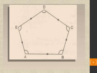
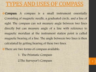
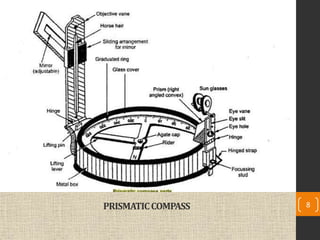
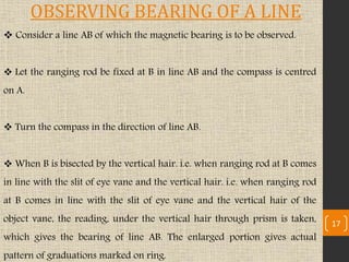
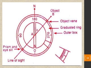
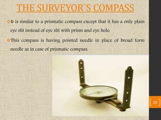
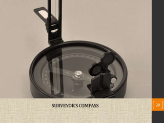
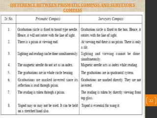
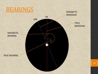
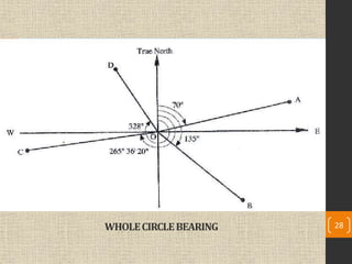
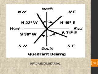
S.S.A.S.I.T, SURAT GTU
Preparedby:-
Miss. Khushbuk. shah
Asst. prof
S.S.A.S.I.T, SURAT
INTRODUCTION
 Chain surveying can be used when the area to be surveyed
is comparatively small and is fairly flat.
 But when the area is large, undulated and crowded with
many details, triangulation (which is the principle of chain
survey) is not possible. In such an area, the method of
traversing is adopted.
2
TRAVERSING
 In Traversing, the framework consist of a number of
connected lines. The length are measured by a chain or a
tape and the directions measured by angle measuring
instruments. In one of the methods, the angle (direction)
measuring instrument is the compass. Hence, in compass
surveying directions of survey lines are determined with a
compass and the length of the lines are measured with a
tape or a chain. This process is known as Compass
Traversing. 3
4
PRINCIPLE OF COMPASS SURVEYING
The Principle of Compass Survey is Traversing; which involves
a series of connected lines the magnetic bearing of the lines are
measured by prismatic compass and the distance (lengths) of
the are measured by chain. Such survey does not require the
formulation of a network of triangle.
Compass surveying is recommended when the area is large,
undulating and crowded with many details.
Compass surveying is not recommended for areas where local
attraction is suspected due to the presence of magnetic
substances like steel structures, iron ore deposits, electric cables
conveying currents, and so on.
5
6
TYPES AND USES OF COMPASS
Compass: A compass is a small instrument essentially
Consisting of magnetic needle, a graduated circle, and a line of
sight. The compass can not measure angle between two lines
directly but can measure angle of a line with reference to
magnetic meridian at the instrument station point is called
magnetic bearing of a line. The angle between two lines is then
calculated by getting bearing of these two lines.
There are two forms of compass available:
1. The Prismatic Compass
2.The Surveyor’s Compass 7
PRISMATICCOMPASS 8
 The Prismatic Compass:- The
prismatic compass is a magnetic
compass which consists of the
following parts.
 Cylindrical Metal Box:-
Cylindrical metal box is having
diameter of 8 to 12 cm. It protects
the compass and forms entire casing
or body of the compass. It protects
compass from dust, rain etc.
9
Pivot
• Pivot is provided at the centre of the compass and
supports freely suspended magnetic needle over it.
Lifting Pin and Lifting Lever
• A lifting pin is provided just below the sight vane.
When the sight vane is folded, it presses the lifting pin.
The lifting pin with the help of lifting lever then lifts
the magnetic needle out of pivot point to prevent
damage to pivot head.
Spring Brake or Brake Pin
• To damp the oscillation of the needle before taking a
reading and to bring it to rest quickly, the light spring
brake attached to the inside of the box is brought in
contact with edge of the ring by gently pressing
inward the brake pin.
10
Magnetic Needle: Magnetic needle is the
heart of the instrument. This needle
measures angles of a line from magnetic
meridian a the needle always remains
pointed towards north and south pole at the
two ends of the needle when freely
suspended on any support.
 Graduated Circle or Ring: This is an
aluminium graduated ring marked with 0 0
to 360 0 to measure all possible bearings of
lines, and attached with the magnetic needle.
The ring is graduated to half a degree.
11
Prism:- Prism is used to read graduations on ring
and to take exact reading by compass. It is placed
exactly opposite to object vane. The prism hole is
protected by prism cap to protected by prism cap to
protect it from dust and moisture.
Object Vane:- Object Vane is diametrically
opposite to the prism and eye vane. The object vane
is carrying a horse hair or black thin wire to sight
object in line with eye sight.
 Eye Vane:- Eye Vane is a fine slit provided with
eye hole at bottom to bisect the object from the slit
and to take reading simultaneously from the eye
hole. This eye vane is provided with prism and can
be lifted up and down by the stud to bisect the object
of higher level.
12
Glass Cover: It covers the instrument box from
the top such that needle and graduated ring is
seen from the top.
 Sun Glasses: These are used when some
luminous objects are to be bisected. These are
placed in front of the eye slit and in bunch of
three or four shades of different colours to give
sharp picture of the object only.
 Reflecting Mirror: It is used to get image of an
object located above or below the instrument
level while bisection. It is placed on the object
vane.
13
• When the needle of the compass is suspended freely. It
always points towards the north. Therefore, all the angles
measured with prismatic compass are with respect to
north (magnetic meridian).
• “The horizontal angle made by a survey line with
reference to magnetic meridian in clockwise direction is
called the bearing of a line.’
• While using the compass, it is usually mounted on a light
tripod which is having vertical spindle in the ball and
socket arrangement to which the compass is screwed.
14
WORKING OF THE PRISMATIC COMPASS
Temporary adjustment of prismatic compass
 The following procedure should be adopted after fixing the prismatic compass on
the tripod for measuring the bearing of a line.
Centering : Centering is the operation in which compass is kept exactly over the
station from where the bearing is to be determined. The centering is checked by
dropping a small pebble from the underside of the compass. If the pebble falls on the
top of the peg then the centering is correct, if not then the centering is corrected by
adjusting the legs of the tripod.
Leveling : Leveling of the compass is done with the aim to freely swing the graduated
circular ring of the prismatic compass. The ball and socket arrangement on the
tripod will help to achieve a proper level of the compass. This can be checked by
rolling round pencil on glass cover.
Focusing : the prism is moved up or down in its slide till the graduations on the
aluminum ring are seen clear, sharp and perfect focus. The position of the prism will
depend upon the vision of the observer.
15
16
 Consider a line AB of which the magnetic bearing is to be observed.
 Let the ranging rod be fixed at B in line AB and the compass is centred
on A.
 Turn the compass in the direction of line AB.
 When B is bisected by the vertical hair. i.e. when ranging rod at B comes
in line with the slit of eye vane and the vertical hair. i.e. when ranging rod
at B comes in line with the slit of eye vane and the vertical hair of the
object vane, the reading, under the vertical hair through prism is taken,
which gives the bearing of line AB. The enlarged portion gives actual
pattern of graduations marked on ring.
17
OBSERVING BEARING OF A LINE
18
THE SURVEYOR`S COMPASS
It is similar to a prismatic compass except that it has a only plain
eye slit instead of eye slit with prism and eye hole.
This compass is having pointed needle in place of broad form
needle as in case of prismatic compass.
19
SURVEYOR’SCOMPASS 20
Working of Surveyor`s Compass
1) Centering
2) LEVELING
3) OBSERVING THE BEARING OF A LINE
First two observation are same as prismatic compass but third
observation differs from that.
 OBSERVING THE BEARING OF A LINE : in this compass ,the reading is
taken from the top of glass and under the tip of north end of the
magnetic needle directly. No prism is provided here. 21
DIFFERENCE BETWEEN PRISMATIC COMPASS AND SURVEYOR’S
COMPASS
22
BEARINGS
The bearing of a line is the horizontal angle which it makes with a
reference line(meridian).
Depending upon the meridian , there are four type of bearings they
are as follows:
1) True Bearing: The true bearing of a line is the horizontal angle
between the true meridian and the survey line. The true bearing is
measured from the true north in the clockwise direction.
2) Magnetic Bearing: The magnetic bearing of a line is the horizontal
angle which the line makes with the magnetic north. 23
24
3) Grid Bearing: The grid bearing of a line is the horizontal
angle which the line makes with the grid meridian.
4) Arbitrary Bearing: The arbitrary baring of a line is the
horizontal angle which the line makes with the arbitrary
meridian.
BEARINGS
TRUE
MERIDIAN
MAGNETIC
MERIDIAN
TRUE BEARING
MAGNETIC
BEARING
A
B
MN
TN
25
DESIGNATION OF BEARING
 The bearing are designated in the following two
system:-
1) Whole Circle Bearing System.(W.C.B)
2) Quadrantal Bearing System.(Q.B)
26
WHOLE CIRCLE BEARING SYSTEM(W.C.B.)
The bearing of a line measured with respect to magnetic meridian in
clockwise direction is called magnetic bearing and its value varies
between 0ᴼ to 360ᴼ.
The quadrant start from north an progress in a clockwise direction
as the first quadrant is 0ᴼ to 90ᴼ in clockwise direction , 2nd 90ᴼ to
180ᴼ , 3rd 180ᴼ to 270ᴼ, and up to 360ᴼ is 4th one.
27
WHOLECIRCLEBEARING 28
QUADRANTAL BEARING SYSTEM(Q.B.)
In this system, the bearing of survey lines are measured with respect
to north line or south line which ever is the nearest to the given
survey line and either in clockwise direction or in anticlockwise
direction.
 The bearing of lines which fall in Ist and IVth Quadrant are
measured with respect to north line is nearer than south line, and
bearing of lines fall in IInd and IIIrd quadrants are measured from
south line as south is the nearer line. The surveyor’s compass
measures the bearing of lines in the quadrant system. 29
QUADRANTALBEARING 30
REDUCED BEARING (R.B)
When the whole circle bearing is converted into Quadrantal
bearing , it is termed as “REDUCED BEARING”.
Thus , the reduced bearing is similar to the Quadrantal bearing.
Its values lies between 0ᴼ to 90ᴼ, but the quadrant should be
mentioned for proper designation.
31
32
The following table should be remembered for conversion of WCB
to RB.
W.C.B OF ANY
LINE
QUADRANT IN
WHICH IT LIES
RULES FOR
CONVERSION
QUADRANT
0 TO 90 I RB=WCB N-E
90 TO 180 II RB=180-WCB S-E
180 TO 270 III RB =WCB-180ᴼ S-W
270 TO 360 IV RB=360ᴼ - WCB N-W
33
FORE BEARING AND BACK BEARING
The bearing of a line measured in the forward direction of the
survey lines is called the ‘fore bearing’(F.B.) of that line.
The bearing of a line measured in direction backward to the
direction of the progress of survey is called the ‘back
bearing’(B.B.) of the line.
34
FB of line AB
BB of line AB
A
NORTH
NORTH
Θ1 Θ2
B
FB of AB = Θ1(from A to B)
BB of AB= Θ2(from B to A)
35
36
Fore Bearing
• The bearing of a line measured in the forward direction (i.e. along the
progress of survey) is known as fore bearing.
Fore Bearing = Back Bearing ± 180°
Back Bearing
• The bearing of a line measured in the Backward direction is known as Back
Bearing.
BB= FB ± 180
• + sign is applied when FB is < 180
• - sign is applied when FB is > 180
• In the quadrantal bearing (i.e. reduced bearing) system the FB and BB are
numerically equal but the quadrant are just opposite.
• For example if the bearing of AB is N 60 0 E, then its BB is S 60 0 W.
37
Computation of Angles
• Observing the bearing of the lines
of a closed traverse, it is possible to
calculate the included angles,
which can be used for plotting the
traverse.
• At the station where two survey
lines meet, two angles are formed-
an exterior angles and an interior
angles. The interior angles or
included angle is generally the
smaller angles(<180ᴼ).
A
B
C
D
38
EXAMPLES
A
E
B
FB
BB
/_A
INCLUDED
ANGLE
AT STATION A,FB of AB and BB of EB were
measured. Difference of these two bearing
give interior angle A.
Angle A =FB OF AB – BB OF EA
EXTERIOR
ANGLE B
BB
B FB
A
C
M
AT STATION B ,FB of BB OF AB were
measured . Difference of these two
bearing will give you exterior angle B.
EXTERIOR ANGLE B=BB OF AB-FB OF
BC
INTERIOR ANGLE B=360ᴼ-EXTERIOR
ANGLE
39
 North end of a freely suspended magnetic needle will
always point towards the magnetic north, if it is not influenced
by any other external forces except the earth’s magnetic field.
 It is common experience that the magnetic needle gets
deflected from its normal position, if placed near magnetic
rocks, iron ore, cables carrying currents or iron electric poles.,
therefore , not reliable unless these are checked against the
presence of local attraction at each station and their
elimination.
40
Local Attraction
Detection of Local Attraction
• The presence of local attraction at any station may be
detected by observing the fore and back bearing of the line. If
the difference between fore and back bearing is 180 0, both
end station are free from local attraction. If not, the
discrepancy may be due to:-
• An error in observation of either fore and back bearing or
both
• Presence of Local Attraction at either station
• Presence of local Attraction at both the stations
41
Local Attraction
• It may be noted that local attraction at any station affects all the magnetic
bearings by an equal amount and hence, the included angles deduced from the
affected bearing are always correct.
• In case the fore and back bearing of neither line of traverse differ by the
permissible error of reading, the mean value of the bearing of the line least
affected may be accepted.
• The correction to other stations, may be made according to the following
methods.
• By calculating the Included Angles at the affected stations
• By checking the required correction, starting from the unaffected bearing.
42
• The horizontal angle between the magnetic meridian and true
meridian is known as ‘Magnetic declination’ .
• When the north end of the magnetic needle is pointed towards
the west side of the true meridian the position is termed as
‘Declination West (ӨW).
• When the north end of the needle is pointed towards east side
of the true meridian the position is termed as ‘Declination East
(Ө E).
43
Magnetic Declination
44
• True Bearing = Magnetic Bearing Declination
• Use + sign when declination is towards East
• Use – sign when declination is towards West
• Magnetic Bearing = True Bearing Declination
• Use + sign when declination is towards West
• Use – sign when declination is towards East 45
Determination of True bearing and and
Magnetic Bearing
1. Determination of True bearing and Magnetic Bearing Example
• The magnetic bearing of a line AB is 135 0 30’. What will be the
true bearing, if the declination is 5 0 15’ W
• The true bearing of a line CD is 2100 45’, what will be its be its
magnetic bearing of the declination is 8 0 15’ W
ANS:- Determination of True bearing and Magnetic Bearing
• True Bearing of AB = Magnetic Bearing – Declination = 135 0
30’ – 5 0 15’ = 130 0 15’
• Magnetic Bearing of AB = True bearing – Declination = 210 0
45’ + 80 15’ = 219 0 46
47

Angular measurement

  • 1.
    S.S.A.S.I.T, SURAT GTU Preparedby:- Miss.Khushbuk. shah Asst. prof S.S.A.S.I.T, SURAT
  • 2.
    INTRODUCTION  Chain surveyingcan be used when the area to be surveyed is comparatively small and is fairly flat.  But when the area is large, undulated and crowded with many details, triangulation (which is the principle of chain survey) is not possible. In such an area, the method of traversing is adopted. 2
  • 3.
    TRAVERSING  In Traversing,the framework consist of a number of connected lines. The length are measured by a chain or a tape and the directions measured by angle measuring instruments. In one of the methods, the angle (direction) measuring instrument is the compass. Hence, in compass surveying directions of survey lines are determined with a compass and the length of the lines are measured with a tape or a chain. This process is known as Compass Traversing. 3
  • 4.
  • 5.
    PRINCIPLE OF COMPASSSURVEYING The Principle of Compass Survey is Traversing; which involves a series of connected lines the magnetic bearing of the lines are measured by prismatic compass and the distance (lengths) of the are measured by chain. Such survey does not require the formulation of a network of triangle. Compass surveying is recommended when the area is large, undulating and crowded with many details. Compass surveying is not recommended for areas where local attraction is suspected due to the presence of magnetic substances like steel structures, iron ore deposits, electric cables conveying currents, and so on. 5
  • 6.
  • 7.
    TYPES AND USESOF COMPASS Compass: A compass is a small instrument essentially Consisting of magnetic needle, a graduated circle, and a line of sight. The compass can not measure angle between two lines directly but can measure angle of a line with reference to magnetic meridian at the instrument station point is called magnetic bearing of a line. The angle between two lines is then calculated by getting bearing of these two lines. There are two forms of compass available: 1. The Prismatic Compass 2.The Surveyor’s Compass 7
  • 8.
  • 9.
     The PrismaticCompass:- The prismatic compass is a magnetic compass which consists of the following parts.  Cylindrical Metal Box:- Cylindrical metal box is having diameter of 8 to 12 cm. It protects the compass and forms entire casing or body of the compass. It protects compass from dust, rain etc. 9
  • 10.
    Pivot • Pivot isprovided at the centre of the compass and supports freely suspended magnetic needle over it. Lifting Pin and Lifting Lever • A lifting pin is provided just below the sight vane. When the sight vane is folded, it presses the lifting pin. The lifting pin with the help of lifting lever then lifts the magnetic needle out of pivot point to prevent damage to pivot head. Spring Brake or Brake Pin • To damp the oscillation of the needle before taking a reading and to bring it to rest quickly, the light spring brake attached to the inside of the box is brought in contact with edge of the ring by gently pressing inward the brake pin. 10
  • 11.
    Magnetic Needle: Magneticneedle is the heart of the instrument. This needle measures angles of a line from magnetic meridian a the needle always remains pointed towards north and south pole at the two ends of the needle when freely suspended on any support.  Graduated Circle or Ring: This is an aluminium graduated ring marked with 0 0 to 360 0 to measure all possible bearings of lines, and attached with the magnetic needle. The ring is graduated to half a degree. 11
  • 12.
    Prism:- Prism isused to read graduations on ring and to take exact reading by compass. It is placed exactly opposite to object vane. The prism hole is protected by prism cap to protected by prism cap to protect it from dust and moisture. Object Vane:- Object Vane is diametrically opposite to the prism and eye vane. The object vane is carrying a horse hair or black thin wire to sight object in line with eye sight.  Eye Vane:- Eye Vane is a fine slit provided with eye hole at bottom to bisect the object from the slit and to take reading simultaneously from the eye hole. This eye vane is provided with prism and can be lifted up and down by the stud to bisect the object of higher level. 12
  • 13.
    Glass Cover: Itcovers the instrument box from the top such that needle and graduated ring is seen from the top.  Sun Glasses: These are used when some luminous objects are to be bisected. These are placed in front of the eye slit and in bunch of three or four shades of different colours to give sharp picture of the object only.  Reflecting Mirror: It is used to get image of an object located above or below the instrument level while bisection. It is placed on the object vane. 13
  • 14.
    • When theneedle of the compass is suspended freely. It always points towards the north. Therefore, all the angles measured with prismatic compass are with respect to north (magnetic meridian). • “The horizontal angle made by a survey line with reference to magnetic meridian in clockwise direction is called the bearing of a line.’ • While using the compass, it is usually mounted on a light tripod which is having vertical spindle in the ball and socket arrangement to which the compass is screwed. 14 WORKING OF THE PRISMATIC COMPASS
  • 15.
    Temporary adjustment ofprismatic compass  The following procedure should be adopted after fixing the prismatic compass on the tripod for measuring the bearing of a line. Centering : Centering is the operation in which compass is kept exactly over the station from where the bearing is to be determined. The centering is checked by dropping a small pebble from the underside of the compass. If the pebble falls on the top of the peg then the centering is correct, if not then the centering is corrected by adjusting the legs of the tripod. Leveling : Leveling of the compass is done with the aim to freely swing the graduated circular ring of the prismatic compass. The ball and socket arrangement on the tripod will help to achieve a proper level of the compass. This can be checked by rolling round pencil on glass cover. Focusing : the prism is moved up or down in its slide till the graduations on the aluminum ring are seen clear, sharp and perfect focus. The position of the prism will depend upon the vision of the observer. 15
  • 16.
  • 17.
     Consider aline AB of which the magnetic bearing is to be observed.  Let the ranging rod be fixed at B in line AB and the compass is centred on A.  Turn the compass in the direction of line AB.  When B is bisected by the vertical hair. i.e. when ranging rod at B comes in line with the slit of eye vane and the vertical hair. i.e. when ranging rod at B comes in line with the slit of eye vane and the vertical hair of the object vane, the reading, under the vertical hair through prism is taken, which gives the bearing of line AB. The enlarged portion gives actual pattern of graduations marked on ring. 17 OBSERVING BEARING OF A LINE
  • 18.
  • 19.
    THE SURVEYOR`S COMPASS Itis similar to a prismatic compass except that it has a only plain eye slit instead of eye slit with prism and eye hole. This compass is having pointed needle in place of broad form needle as in case of prismatic compass. 19
  • 20.
  • 21.
    Working of Surveyor`sCompass 1) Centering 2) LEVELING 3) OBSERVING THE BEARING OF A LINE First two observation are same as prismatic compass but third observation differs from that.  OBSERVING THE BEARING OF A LINE : in this compass ,the reading is taken from the top of glass and under the tip of north end of the magnetic needle directly. No prism is provided here. 21
  • 22.
    DIFFERENCE BETWEEN PRISMATICCOMPASS AND SURVEYOR’S COMPASS 22
  • 23.
    BEARINGS The bearing ofa line is the horizontal angle which it makes with a reference line(meridian). Depending upon the meridian , there are four type of bearings they are as follows: 1) True Bearing: The true bearing of a line is the horizontal angle between the true meridian and the survey line. The true bearing is measured from the true north in the clockwise direction. 2) Magnetic Bearing: The magnetic bearing of a line is the horizontal angle which the line makes with the magnetic north. 23
  • 24.
    24 3) Grid Bearing:The grid bearing of a line is the horizontal angle which the line makes with the grid meridian. 4) Arbitrary Bearing: The arbitrary baring of a line is the horizontal angle which the line makes with the arbitrary meridian.
  • 25.
  • 26.
    DESIGNATION OF BEARING The bearing are designated in the following two system:- 1) Whole Circle Bearing System.(W.C.B) 2) Quadrantal Bearing System.(Q.B) 26
  • 27.
    WHOLE CIRCLE BEARINGSYSTEM(W.C.B.) The bearing of a line measured with respect to magnetic meridian in clockwise direction is called magnetic bearing and its value varies between 0ᴼ to 360ᴼ. The quadrant start from north an progress in a clockwise direction as the first quadrant is 0ᴼ to 90ᴼ in clockwise direction , 2nd 90ᴼ to 180ᴼ , 3rd 180ᴼ to 270ᴼ, and up to 360ᴼ is 4th one. 27
  • 28.
  • 29.
    QUADRANTAL BEARING SYSTEM(Q.B.) Inthis system, the bearing of survey lines are measured with respect to north line or south line which ever is the nearest to the given survey line and either in clockwise direction or in anticlockwise direction.  The bearing of lines which fall in Ist and IVth Quadrant are measured with respect to north line is nearer than south line, and bearing of lines fall in IInd and IIIrd quadrants are measured from south line as south is the nearer line. The surveyor’s compass measures the bearing of lines in the quadrant system. 29
  • 30.
  • 31.
    REDUCED BEARING (R.B) Whenthe whole circle bearing is converted into Quadrantal bearing , it is termed as “REDUCED BEARING”. Thus , the reduced bearing is similar to the Quadrantal bearing. Its values lies between 0ᴼ to 90ᴼ, but the quadrant should be mentioned for proper designation. 31
  • 32.
  • 33.
    The following tableshould be remembered for conversion of WCB to RB. W.C.B OF ANY LINE QUADRANT IN WHICH IT LIES RULES FOR CONVERSION QUADRANT 0 TO 90 I RB=WCB N-E 90 TO 180 II RB=180-WCB S-E 180 TO 270 III RB =WCB-180ᴼ S-W 270 TO 360 IV RB=360ᴼ - WCB N-W 33
  • 34.
    FORE BEARING ANDBACK BEARING The bearing of a line measured in the forward direction of the survey lines is called the ‘fore bearing’(F.B.) of that line. The bearing of a line measured in direction backward to the direction of the progress of survey is called the ‘back bearing’(B.B.) of the line. 34
  • 35.
    FB of lineAB BB of line AB A NORTH NORTH Θ1 Θ2 B FB of AB = Θ1(from A to B) BB of AB= Θ2(from B to A) 35
  • 36.
  • 37.
    Fore Bearing • Thebearing of a line measured in the forward direction (i.e. along the progress of survey) is known as fore bearing. Fore Bearing = Back Bearing ± 180° Back Bearing • The bearing of a line measured in the Backward direction is known as Back Bearing. BB= FB ± 180 • + sign is applied when FB is < 180 • - sign is applied when FB is > 180 • In the quadrantal bearing (i.e. reduced bearing) system the FB and BB are numerically equal but the quadrant are just opposite. • For example if the bearing of AB is N 60 0 E, then its BB is S 60 0 W. 37
  • 38.
    Computation of Angles •Observing the bearing of the lines of a closed traverse, it is possible to calculate the included angles, which can be used for plotting the traverse. • At the station where two survey lines meet, two angles are formed- an exterior angles and an interior angles. The interior angles or included angle is generally the smaller angles(<180ᴼ). A B C D 38
  • 39.
    EXAMPLES A E B FB BB /_A INCLUDED ANGLE AT STATION A,FBof AB and BB of EB were measured. Difference of these two bearing give interior angle A. Angle A =FB OF AB – BB OF EA EXTERIOR ANGLE B BB B FB A C M AT STATION B ,FB of BB OF AB were measured . Difference of these two bearing will give you exterior angle B. EXTERIOR ANGLE B=BB OF AB-FB OF BC INTERIOR ANGLE B=360ᴼ-EXTERIOR ANGLE 39
  • 40.
     North endof a freely suspended magnetic needle will always point towards the magnetic north, if it is not influenced by any other external forces except the earth’s magnetic field.  It is common experience that the magnetic needle gets deflected from its normal position, if placed near magnetic rocks, iron ore, cables carrying currents or iron electric poles., therefore , not reliable unless these are checked against the presence of local attraction at each station and their elimination. 40 Local Attraction
  • 41.
    Detection of LocalAttraction • The presence of local attraction at any station may be detected by observing the fore and back bearing of the line. If the difference between fore and back bearing is 180 0, both end station are free from local attraction. If not, the discrepancy may be due to:- • An error in observation of either fore and back bearing or both • Presence of Local Attraction at either station • Presence of local Attraction at both the stations 41
  • 42.
    Local Attraction • Itmay be noted that local attraction at any station affects all the magnetic bearings by an equal amount and hence, the included angles deduced from the affected bearing are always correct. • In case the fore and back bearing of neither line of traverse differ by the permissible error of reading, the mean value of the bearing of the line least affected may be accepted. • The correction to other stations, may be made according to the following methods. • By calculating the Included Angles at the affected stations • By checking the required correction, starting from the unaffected bearing. 42
  • 43.
    • The horizontalangle between the magnetic meridian and true meridian is known as ‘Magnetic declination’ . • When the north end of the magnetic needle is pointed towards the west side of the true meridian the position is termed as ‘Declination West (ӨW). • When the north end of the needle is pointed towards east side of the true meridian the position is termed as ‘Declination East (Ө E). 43 Magnetic Declination
  • 44.
  • 45.
    • True Bearing= Magnetic Bearing Declination • Use + sign when declination is towards East • Use – sign when declination is towards West • Magnetic Bearing = True Bearing Declination • Use + sign when declination is towards West • Use – sign when declination is towards East 45 Determination of True bearing and and Magnetic Bearing
  • 46.
    1. Determination ofTrue bearing and Magnetic Bearing Example • The magnetic bearing of a line AB is 135 0 30’. What will be the true bearing, if the declination is 5 0 15’ W • The true bearing of a line CD is 2100 45’, what will be its be its magnetic bearing of the declination is 8 0 15’ W ANS:- Determination of True bearing and Magnetic Bearing • True Bearing of AB = Magnetic Bearing – Declination = 135 0 30’ – 5 0 15’ = 130 0 15’ • Magnetic Bearing of AB = True bearing – Declination = 210 0 45’ + 80 15’ = 219 0 46
  • 47.