This document discusses various surveying techniques for setting out perpendiculars, offsets, and angles using ranging, theodolites, cross-staffs, optical squares, and prism squares.
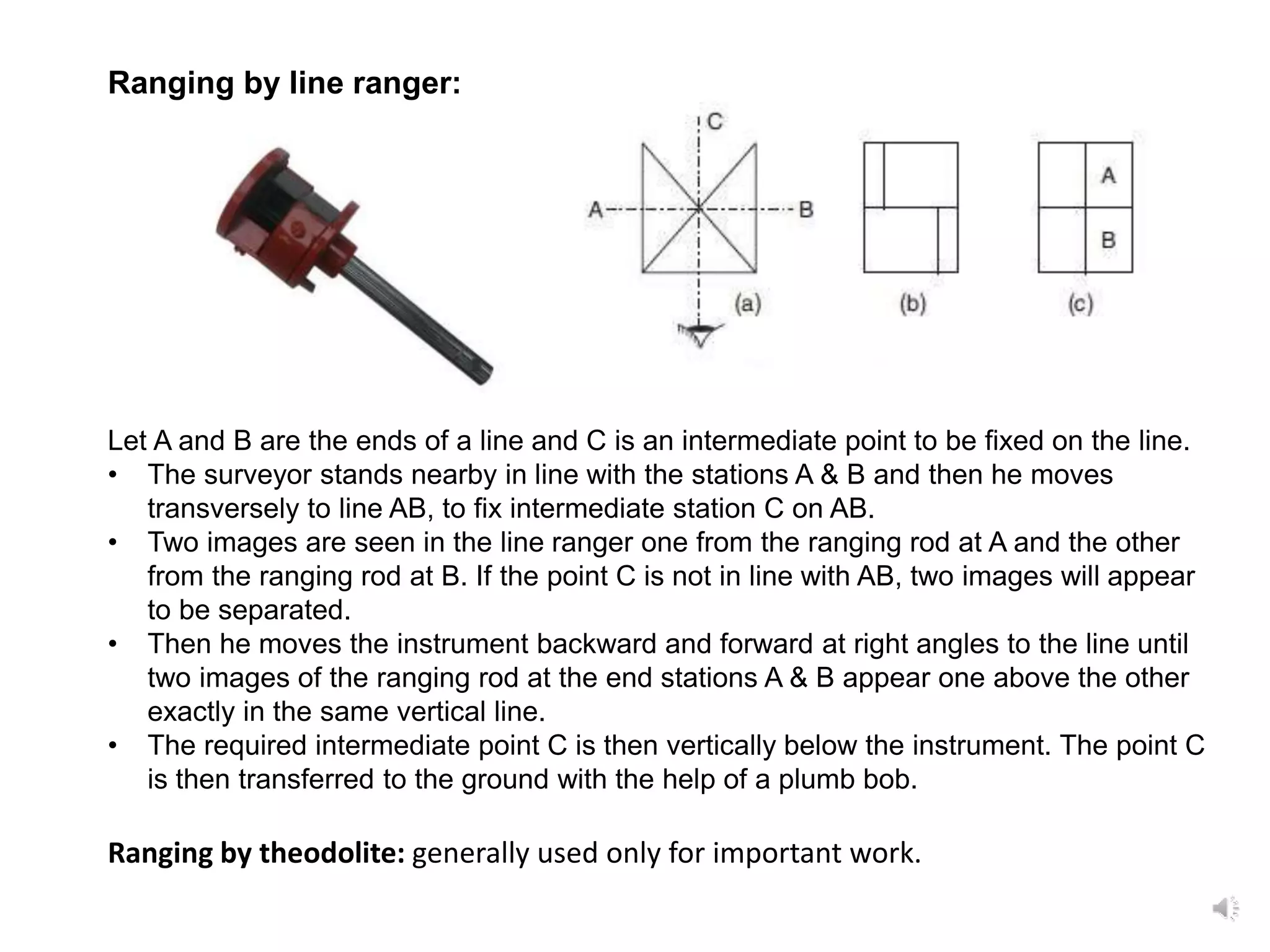
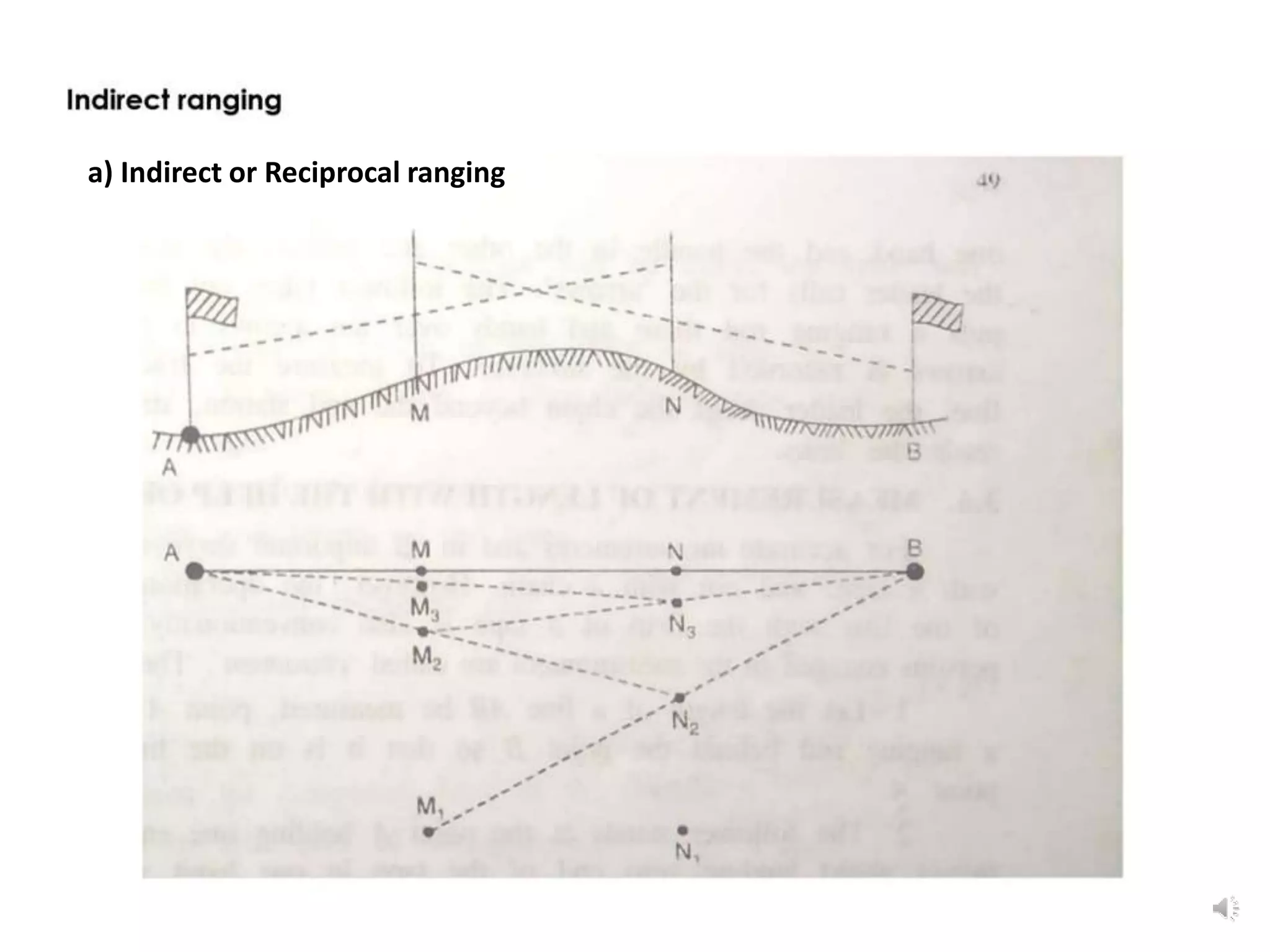
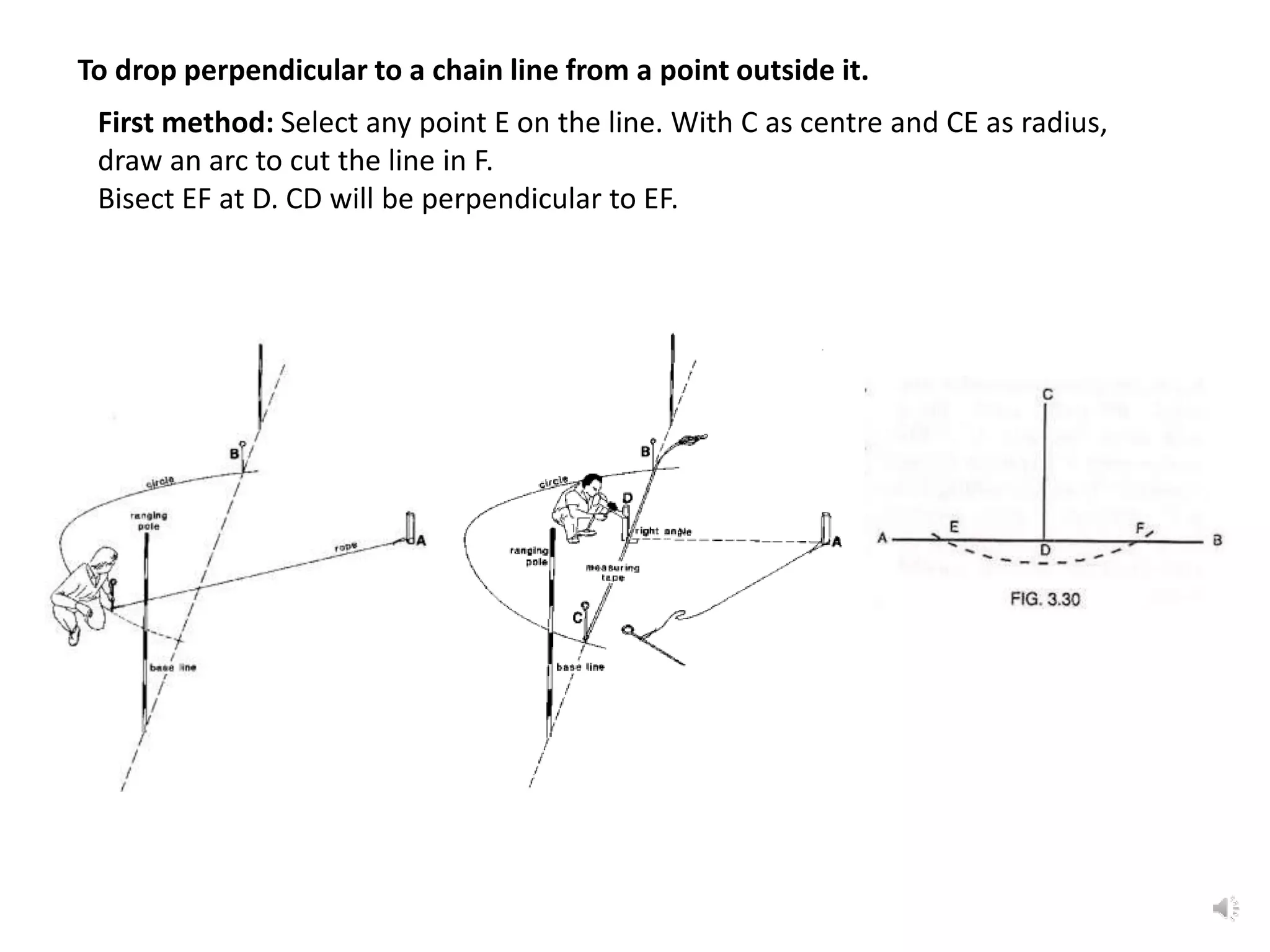
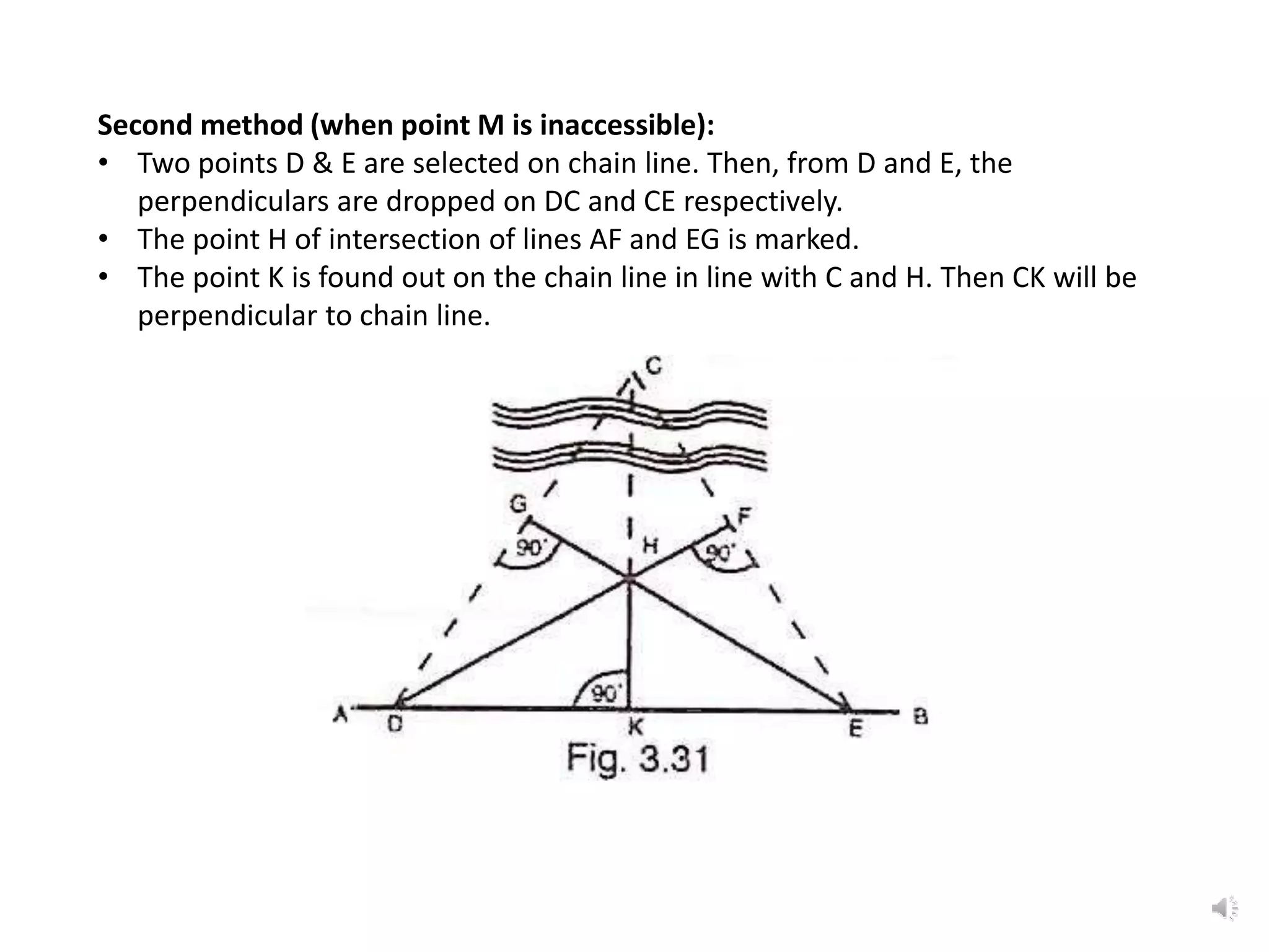
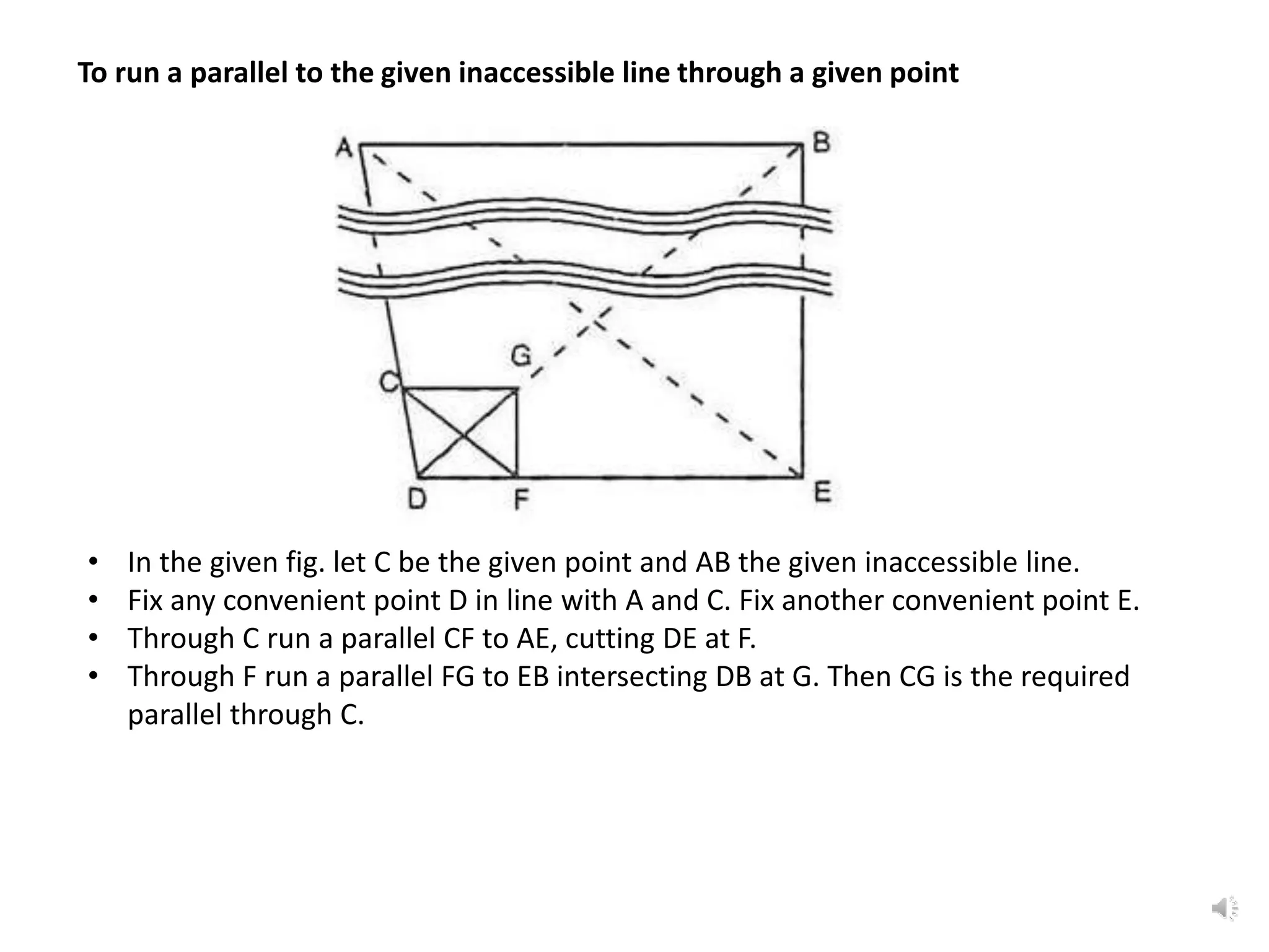
It describes how to use ranging by line ranger or theodolite to fix intermediate points on a line. It also explains different methods for setting out right angles using chains, offsets, bisection, and known lengths. Techniques are provided for dropping perpendiculars to accessible and inaccessible lines.
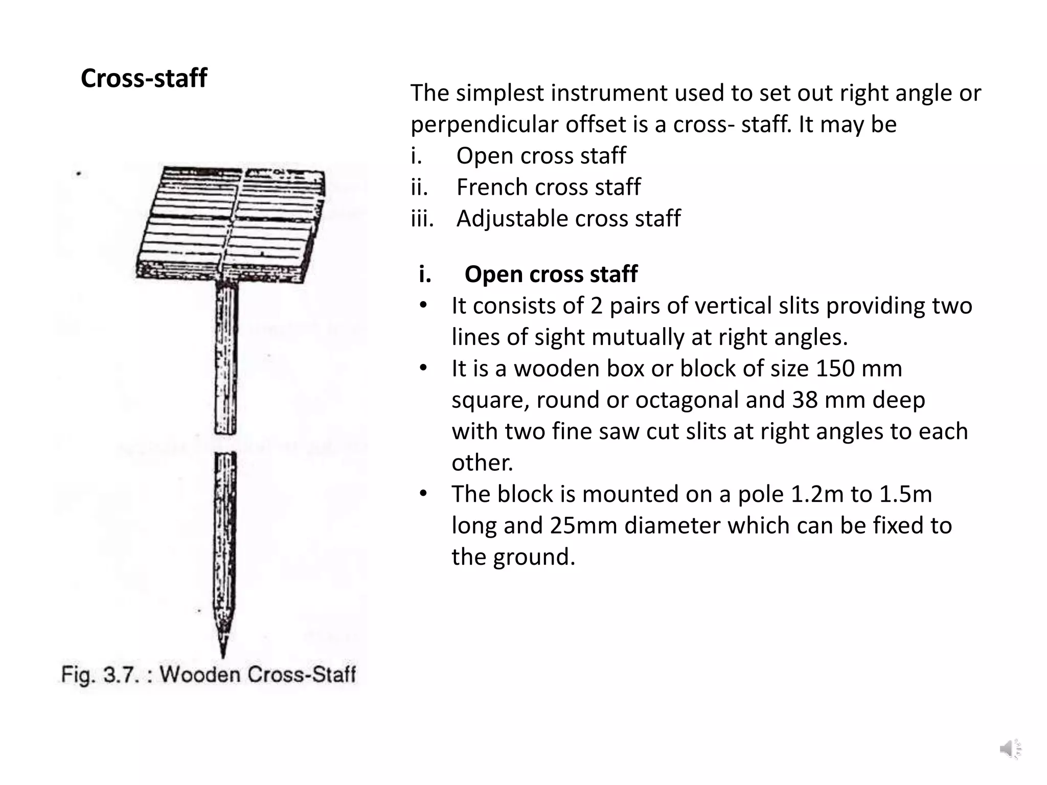
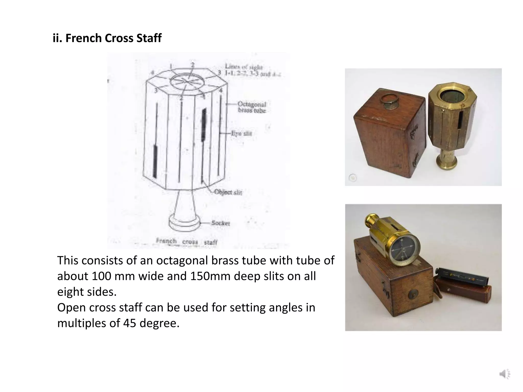
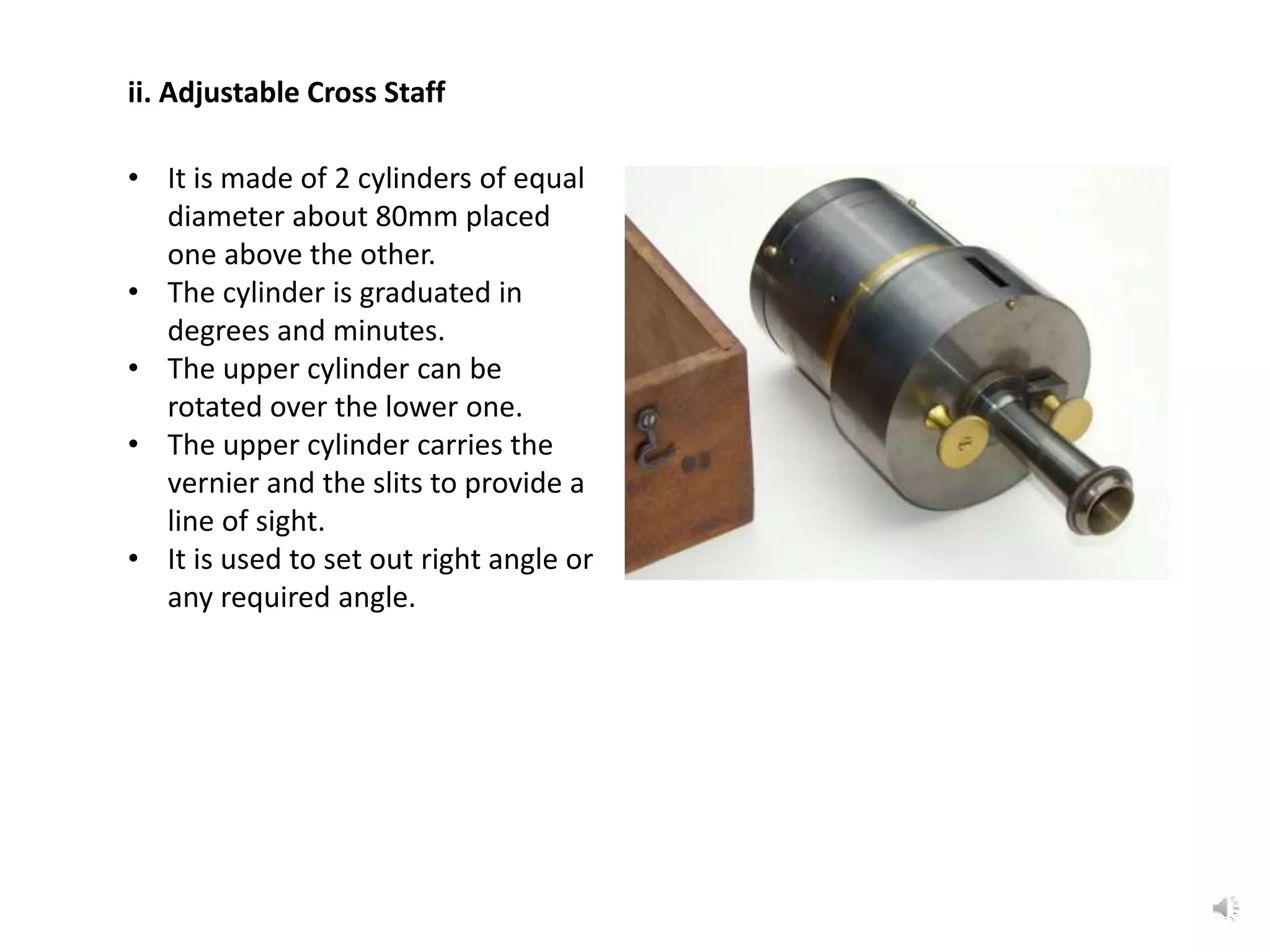
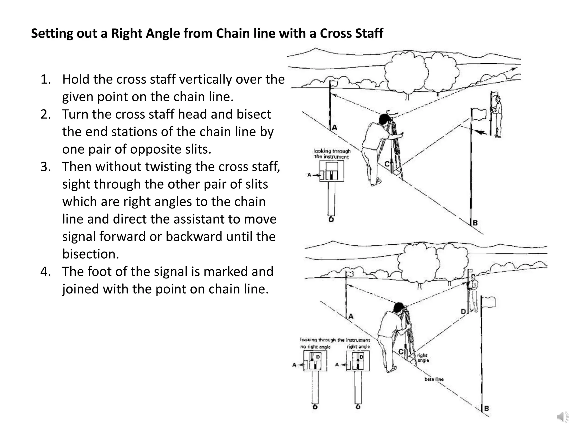
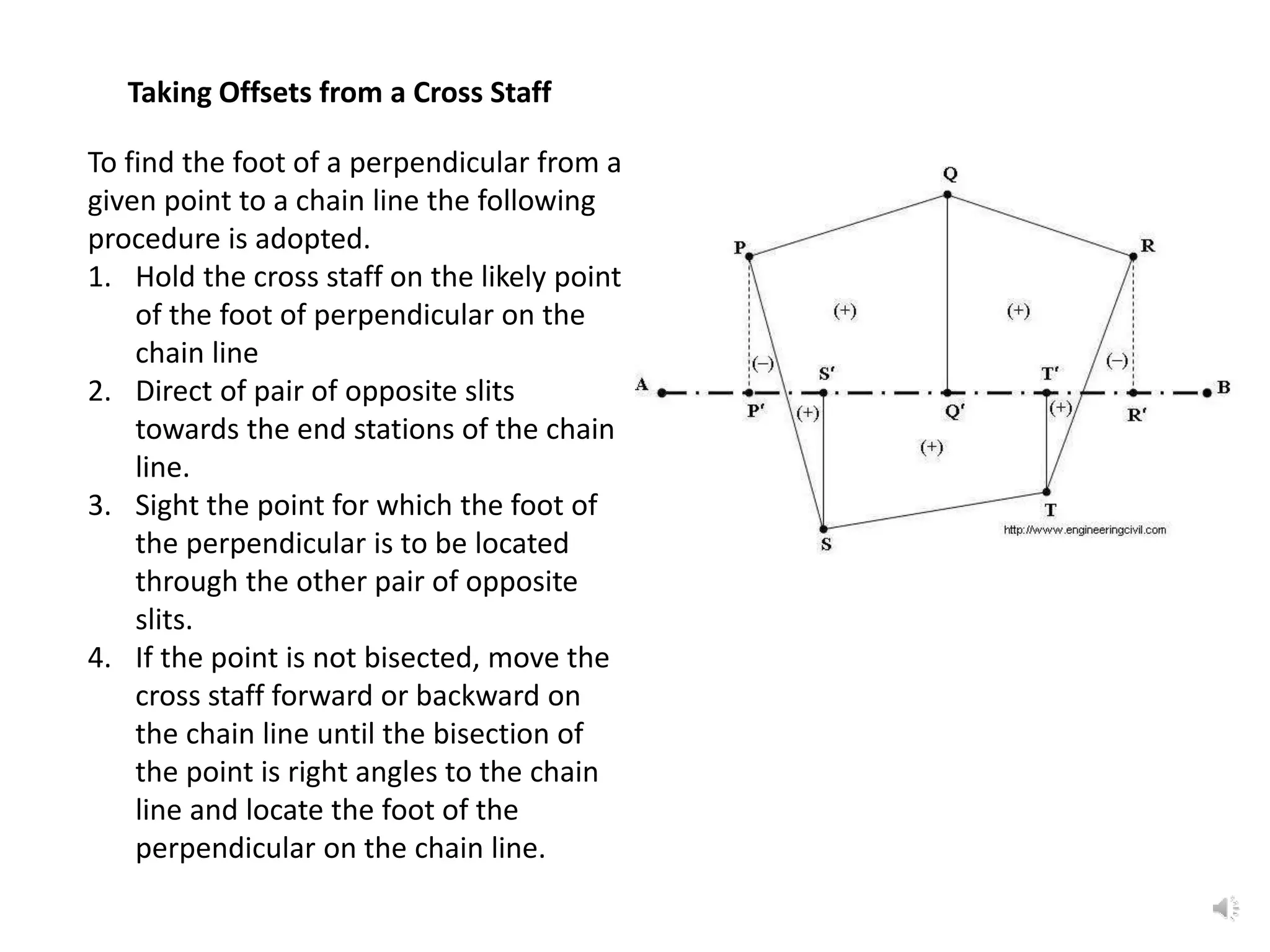
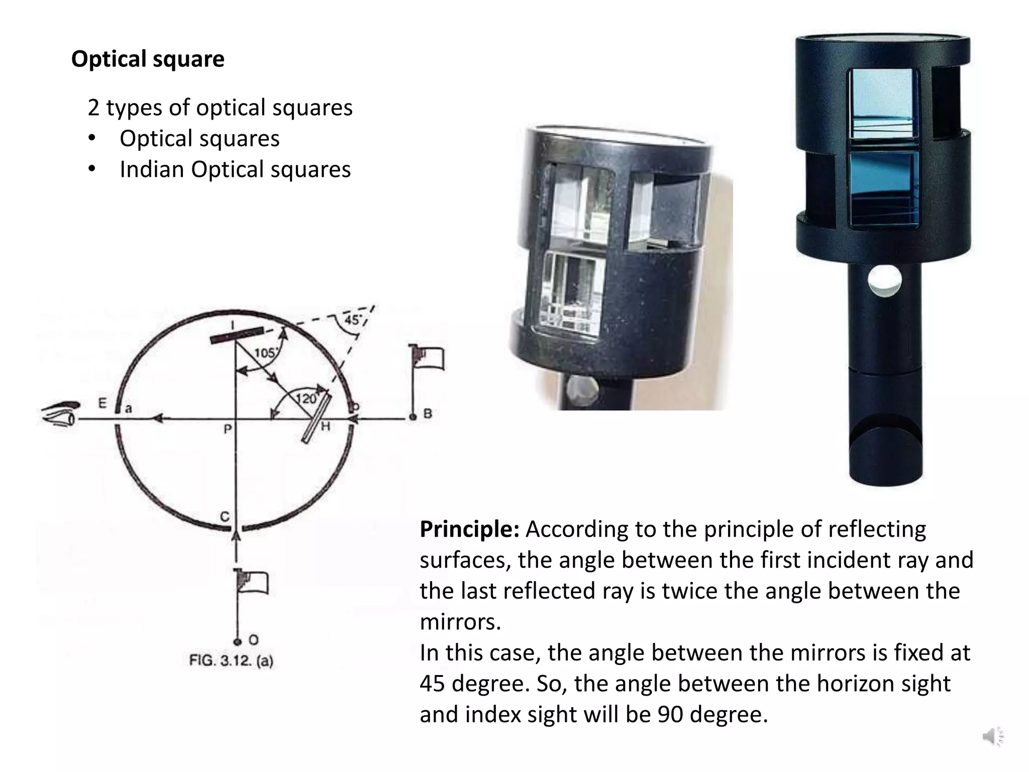
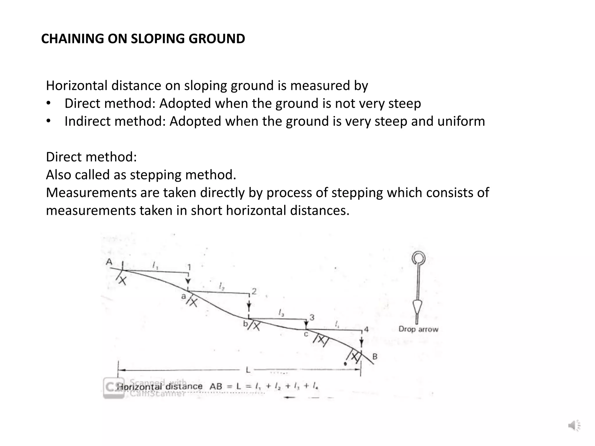
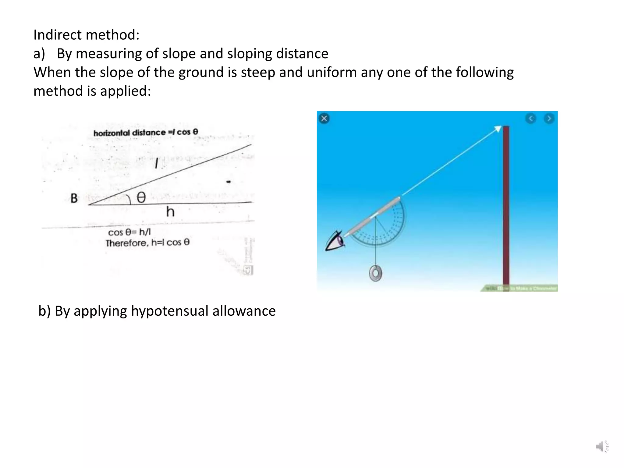
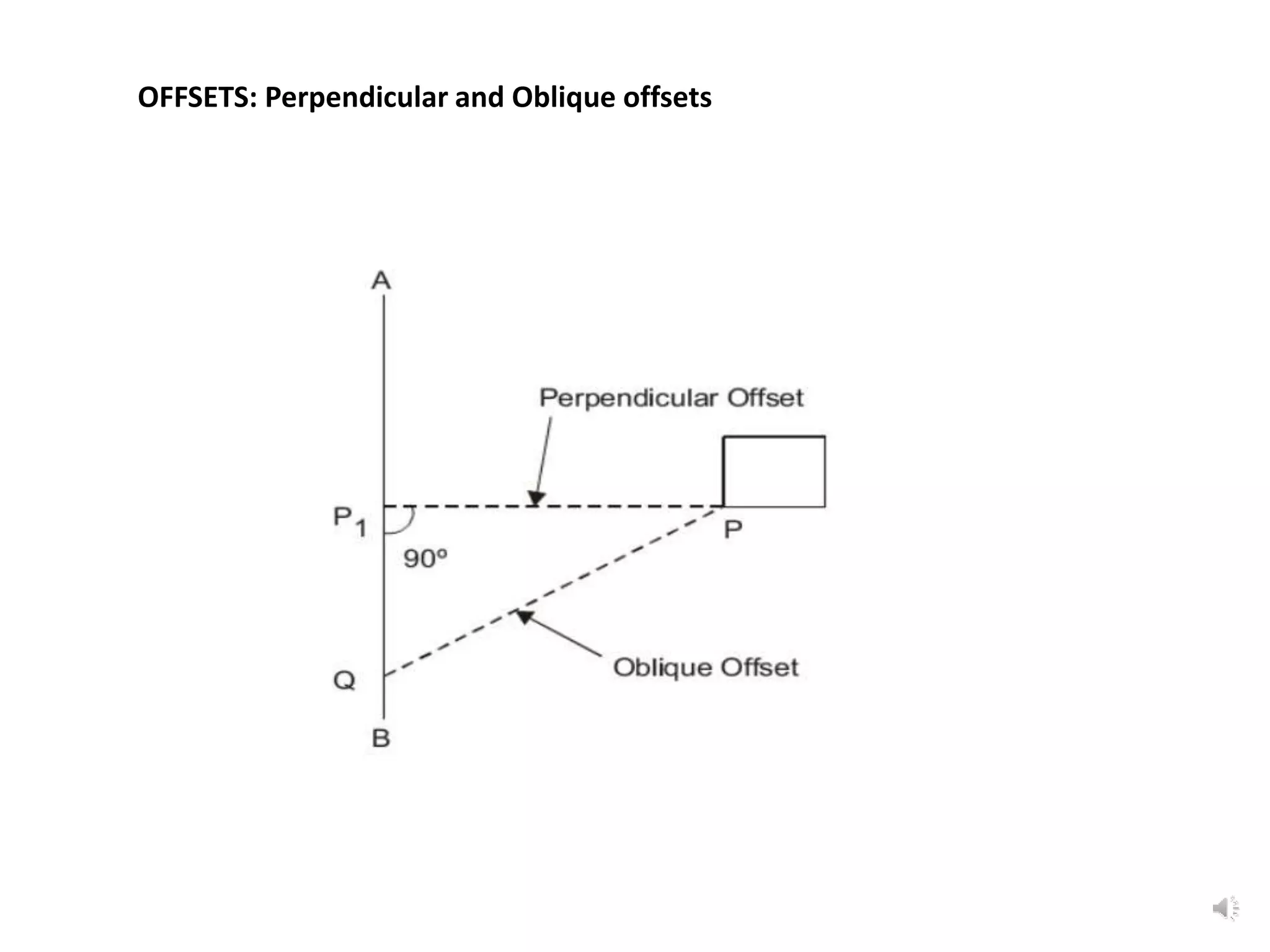
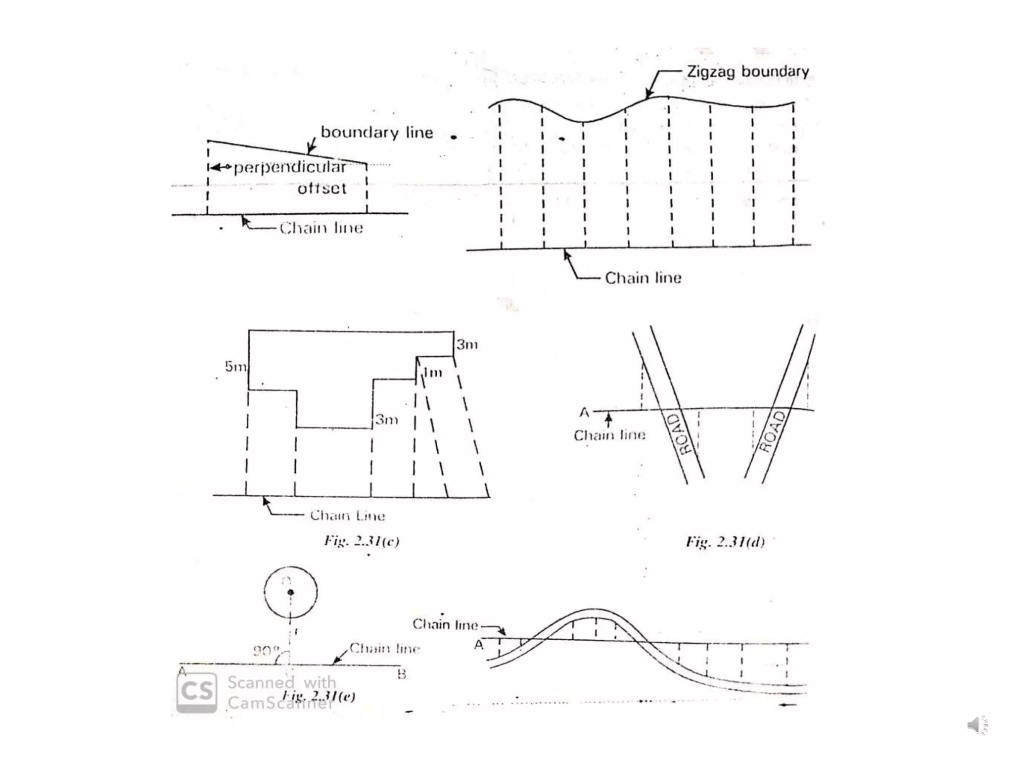
The document outlines the use of various manual instruments like cross-staffs, optical squares, and prism squares to take perpendicular and oblique offsets from chain lines and set out angles. It also discusses measuring horizontal distances
Introduction to surveying, ranging and chainingShital Navghare
This presentation contains the complete introduction of surveying. It also includes all the instrucments used in linear measurement and the terms related to Ranging and Chaining
Introduction, classification of curves, Elements of a simple circular, designation of curve, methods of setting out a simple circular curve, elements of a compound and reverse curves, transition curve, types of transition curves, combined curve, types of vertical curves
CURVE 1- THIS SLIDE CONTAINS WHOLE SYLLABUS OF ENGINEERING DRAWING/GRAPHICS. IT IS THE MOST SIMPLE AND INTERACTIVE WAY TO LEARN ENGINEERING DRAWING.SYLLABUS IS RELATED TO rajiv gandhi proudyogiki vishwavidyalaya / rajiv gandhi TECHNICAL UNIVERSITY ,BHOPAL.
An Approach to Detecting Writing Styles Based on Clustering Techniquesambekarshweta25
An Approach to Detecting Writing Styles Based on Clustering Techniques
Authors:
-Devkinandan Jagtap
-Shweta Ambekar
-Harshit Singh
-Nakul Sharma (Assistant Professor)
Institution:
VIIT Pune, India
Abstract:
This paper proposes a system to differentiate between human-generated and AI-generated texts using stylometric analysis. The system analyzes text files and classifies writing styles by employing various clustering algorithms, such as k-means, k-means++, hierarchical, and DBSCAN. The effectiveness of these algorithms is measured using silhouette scores. The system successfully identifies distinct writing styles within documents, demonstrating its potential for plagiarism detection.
Introduction:
Stylometry, the study of linguistic and structural features in texts, is used for tasks like plagiarism detection, genre separation, and author verification. This paper leverages stylometric analysis to identify different writing styles and improve plagiarism detection methods.
Methodology:
The system includes data collection, preprocessing, feature extraction, dimensional reduction, machine learning models for clustering, and performance comparison using silhouette scores. Feature extraction focuses on lexical features, vocabulary richness, and readability scores. The study uses a small dataset of texts from various authors and employs algorithms like k-means, k-means++, hierarchical clustering, and DBSCAN for clustering.
Results:
Experiments show that the system effectively identifies writing styles, with silhouette scores indicating reasonable to strong clustering when k=2. As the number of clusters increases, the silhouette scores decrease, indicating a drop in accuracy. K-means and k-means++ perform similarly, while hierarchical clustering is less optimized.
Conclusion and Future Work:
The system works well for distinguishing writing styles with two clusters but becomes less accurate as the number of clusters increases. Future research could focus on adding more parameters and optimizing the methodology to improve accuracy with higher cluster values. This system can enhance existing plagiarism detection tools, especially in academic settings.
NO1 Uk best vashikaran specialist in delhi vashikaran baba near me online vas...Amil Baba Dawood bangali
Contact with Dawood Bhai Just call on +92322-6382012 and we'll help you. We'll solve all your problems within 12 to 24 hours and with 101% guarantee and with astrology systematic. If you want to take any personal or professional advice then also you can call us on +92322-6382012 , ONLINE LOVE PROBLEM & Other all types of Daily Life Problem's.Then CALL or WHATSAPP us on +92322-6382012 and Get all these problems solutions here by Amil Baba DAWOOD BANGALI
#vashikaranspecialist #astrologer #palmistry #amliyaat #taweez #manpasandshadi #horoscope #spiritual #lovelife #lovespell #marriagespell#aamilbabainpakistan #amilbabainkarachi #powerfullblackmagicspell #kalajadumantarspecialist #realamilbaba #AmilbabainPakistan #astrologerincanada #astrologerindubai #lovespellsmaster #kalajaduspecialist #lovespellsthatwork #aamilbabainlahore#blackmagicformarriage #aamilbaba #kalajadu #kalailam #taweez #wazifaexpert #jadumantar #vashikaranspecialist #astrologer #palmistry #amliyaat #taweez #manpasandshadi #horoscope #spiritual #lovelife #lovespell #marriagespell#aamilbabainpakistan #amilbabainkarachi #powerfullblackmagicspell #kalajadumantarspecialist #realamilbaba #AmilbabainPakistan #astrologerincanada #astrologerindubai #lovespellsmaster #kalajaduspecialist #lovespellsthatwork #aamilbabainlahore #blackmagicforlove #blackmagicformarriage #aamilbaba #kalajadu #kalailam #taweez #wazifaexpert #jadumantar #vashikaranspecialist #astrologer #palmistry #amliyaat #taweez #manpasandshadi #horoscope #spiritual #lovelife #lovespell #marriagespell#aamilbabainpakistan #amilbabainkarachi #powerfullblackmagicspell #kalajadumantarspecialist #realamilbaba #AmilbabainPakistan #astrologerincanada #astrologerindubai #lovespellsmaster #kalajaduspecialist #lovespellsthatwork #aamilbabainlahore #Amilbabainuk #amilbabainspain #amilbabaindubai #Amilbabainnorway #amilbabainkrachi #amilbabainlahore #amilbabaingujranwalan #amilbabainislamabad
Forklift Classes Overview by Intella PartsIntella Parts
Discover the different forklift classes and their specific applications. Learn how to choose the right forklift for your needs to ensure safety, efficiency, and compliance in your operations.
For more technical information, visit our website https://intellaparts.com
Industrial Training at Shahjalal Fertilizer Company Limited (SFCL)MdTanvirMahtab2
This presentation is about the working procedure of Shahjalal Fertilizer Company Limited (SFCL). A Govt. owned Company of Bangladesh Chemical Industries Corporation under Ministry of Industries.
Hierarchical Digital Twin of a Naval Power SystemKerry Sado
A hierarchical digital twin of a Naval DC power system has been developed and experimentally verified. Similar to other state-of-the-art digital twins, this technology creates a digital replica of the physical system executed in real-time or faster, which can modify hardware controls. However, its advantage stems from distributing computational efforts by utilizing a hierarchical structure composed of lower-level digital twin blocks and a higher-level system digital twin. Each digital twin block is associated with a physical subsystem of the hardware and communicates with a singular system digital twin, which creates a system-level response. By extracting information from each level of the hierarchy, power system controls of the hardware were reconfigured autonomously. This hierarchical digital twin development offers several advantages over other digital twins, particularly in the field of naval power systems. The hierarchical structure allows for greater computational efficiency and scalability while the ability to autonomously reconfigure hardware controls offers increased flexibility and responsiveness. The hierarchical decomposition and models utilized were well aligned with the physical twin, as indicated by the maximum deviations between the developed digital twin hierarchy and the hardware.
Understanding Inductive Bias in Machine LearningSUTEJAS
This presentation explores the concept of inductive bias in machine learning. It explains how algorithms come with built-in assumptions and preferences that guide the learning process. You'll learn about the different types of inductive bias and how they can impact the performance and generalizability of machine learning models.
The presentation also covers the positive and negative aspects of inductive bias, along with strategies for mitigating potential drawbacks. We'll explore examples of how bias manifests in algorithms like neural networks and decision trees.
By understanding inductive bias, you can gain valuable insights into how machine learning models work and make informed decisions when building and deploying them.
Using recycled concrete aggregates (RCA) for pavements is crucial to achieving sustainability. Implementing RCA for new pavement can minimize carbon footprint, conserve natural resources, reduce harmful emissions, and lower life cycle costs. Compared to natural aggregate (NA), RCA pavement has fewer comprehensive studies and sustainability assessments.
7. Ranging by line ranger:
Let A and B are the ends of a line and C is an intermediate point to be fixed on the line.
• The surveyor stands nearby in line with the stations A & B and then he moves
transversely to line AB, to fix intermediate station C on AB.
• Two images are seen in the line ranger one from the ranging rod at A and the other
from the ranging rod at B. If the point C is not in line with AB, two images will appear
to be separated.
• Then he moves the instrument backward and forward at right angles to the line until
two images of the ranging rod at the end stations A & B appear one above the other
exactly in the same vertical line.
• The required intermediate point C is then vertically below the instrument. The point C
is then transferred to the ground with the help of a plumb bob.
Ranging by theodolite: generally used only for important work.
15. 2nd method: Select 2 points on chain line such that PO=QO. Then a known length,
say 10m, of the tape is stretched until the mark 5m (10m/2) is obtained and it is
marked by the point R. Now OR is perpendicular to PQ
16. To drop perpendicular to a chain line from a point outside it.
First method: Select any point E on the line. With C as centre and CE as radius,
draw an arc to cut the line in F.
Bisect EF at D. CD will be perpendicular to EF.
17. Second method (when point M is inaccessible):
• Two points D & E are selected on chain line. Then, from D and E, the
perpendiculars are dropped on DC and CE respectively.
• The point H of intersection of lines AF and EG is marked.
• The point K is found out on the chain line in line with C and H. Then CK will be
perpendicular to chain line.
18. To run parallel to a given line through a given point
• Let AB be the given line and C the point through which a parallel is to be run.
• From C drop a perpendicular to AB and measure CD.
• Select any convenient point E on AB and erect a perpendicular EF, making it equal
to CD.
• CF is then the required parallel.
19. • Take any convenient point D on the given line AB. Measure CD and bisect it at
F.
• Select another convenient point E on the line AB.
• Join EF and prolong it to G making FG equal to EF.
• The line joining C and G is the required parallel.
20. To run a parallel to the given inaccessible line through a given point
• In the given fig. let C be the given point and AB the given inaccessible line.
• Fix any convenient point D in line with A and C. Fix another convenient point E.
• Through C run a parallel CF to AE, cutting DE at F.
• Through F run a parallel FG to EB intersecting DB at G. Then CG is the required
parallel through C.
21. Cross-staff The simplest instrument used to set out right angle or
perpendicular offset is a cross- staff. It may be
i. Open cross staff
ii. French cross staff
iii. Adjustable cross staff
i. Open cross staff
• It consists of 2 pairs of vertical slits providing two
lines of sight mutually at right angles.
• It is a wooden box or block of size 150 mm
square, round or octagonal and 38 mm deep
with two fine saw cut slits at right angles to each
other.
• The block is mounted on a pole 1.2m to 1.5m
long and 25mm diameter which can be fixed to
the ground.
22. This consists of an octagonal brass tube with tube of
about 100 mm wide and 150mm deep slits on all
eight sides.
Open cross staff can be used for setting angles in
multiples of 45 degree.
ii. French Cross Staff
23. ii. Adjustable Cross Staff
• It is made of 2 cylinders of equal
diameter about 80mm placed
one above the other.
• The cylinder is graduated in
degrees and minutes.
• The upper cylinder can be
rotated over the lower one.
• The upper cylinder carries the
vernier and the slits to provide a
line of sight.
• It is used to set out right angle or
any required angle.
24. Setting out a Right Angle from Chain line with a Cross Staff
1. Hold the cross staff vertically over the
given point on the chain line.
2. Turn the cross staff head and bisect
the end stations of the chain line by
one pair of opposite slits.
3. Then without twisting the cross staff,
sight through the other pair of slits
which are right angles to the chain
line and direct the assistant to move
signal forward or backward until the
bisection.
4. The foot of the signal is marked and
joined with the point on chain line.
25. Taking Offsets from a Cross Staff
To find the foot of a perpendicular from a
given point to a chain line the following
procedure is adopted.
1. Hold the cross staff on the likely point
of the foot of perpendicular on the
chain line
2. Direct of pair of opposite slits
towards the end stations of the chain
line.
3. Sight the point for which the foot of
the perpendicular is to be located
through the other pair of opposite
slits.
4. If the point is not bisected, move the
cross staff forward or backward on
the chain line until the bisection of
the point is right angles to the chain
line and locate the foot of the
perpendicular on the chain line.
26. Optical square
2 types of optical squares
• Optical squares
• Indian Optical squares
Principle: According to the principle of reflecting
surfaces, the angle between the first incident ray and
the last reflected ray is twice the angle between the
mirrors.
In this case, the angle between the mirrors is fixed at
45 degree. So, the angle between the horizon sight
and index sight will be 90 degree.
27. To set out a perpendicular to a chain line AB at a given point C.
1. Stand on the chain line holding the instrument over the point C and sight the
ranging rod at B through the unsilvered portion of the horizon glass.
2. Direct the staff man to move his ranging rod D to the right or left as found necessary
until its image is seen in the silvered portion of the horizon glass exactly in
coincidence with the ranging rod at B.
3. The line CD is the required perpendicular to the given line AB.
28. Indian Optical Square
It is a brass wedge shaped hollow box of 50mm sides and 30mm deep with two
mirrors M and N fixed to the inclined sides at an angle of 45 degree. Two rectangular
openings a and b are provided in the sides above these mirrors for sighting the
ranging rod on the chain line. ABCD is the open face of the square which is kept
towards the object to which an offset is to be taken.
29. Uses of an optical square
a) Taking offsets to objects from the Chain line:
1. Hold the instrument in a hand.
2. Stand on the chain line AB and turn its open face ABCD towards the object C.
3. Sight the ranging rod at the forward station B looking through the opening in
the direction of a or b according as the object C is on the right or on the left.
4. Walk along the chain line AB forward and backward until the image of the
object C, appears exactly in coincidence with the ranging rod at B.
5. The plumb line suspended from the handle gives the required point on the
chain line.
b) Setting out right angles at given points on a chain line:
The procedure is similar to that of an optical square explained earlier.
30. Prism square
It is based on the same principle as the optical square and is used in the same
manner. It has an advantage over the optical square i.e., no adjustment is required,
since the angles between the reflecting surfaces of prisms is kept fixed (45 degree) as
shown in fig unaffected by dust.etc.
31. CHAINING ON SLOPING GROUND
Horizontal distance on sloping ground is measured by
• Direct method: Adopted when the ground is not very steep
• Indirect method: Adopted when the ground is very steep and uniform
Direct method:
Also called as stepping method.
Measurements are taken directly by process of stepping which consists of
measurements taken in short horizontal distances.
32. Indirect method:
a) By measuring of slope and sloping distance
When the slope of the ground is steep and uniform any one of the following
method is applied:
b) By applying hypotensual allowance