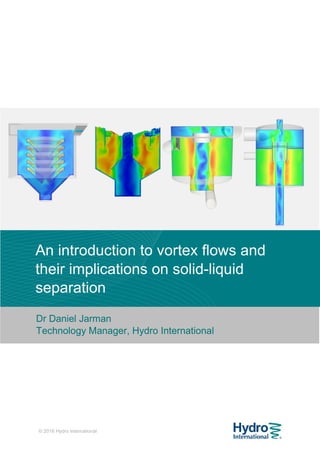
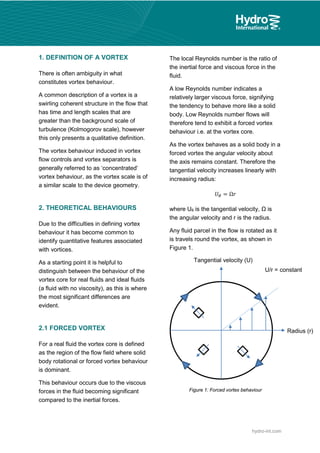
There is often ambiguity in what constitutes vortex behaviour, and common descriptions are qualitative in nature and therefore necessarily limited. It has become common to identify quantitative features associated with vortices in order to provide a definition.
A full understanding of real-world vortex behaviour enables engineers to develop hydrodynamic separators that minimise short circuiting and maximise the residence time of the fluid, ensuring that the best use is made of the available volumes. With this understanding, separation units can be designed to be resistant to changes in inflow conditions, enabling them to collect a wide range of materials across a wide range of flow rates.
Fluid MechanicsVortex flow and impulse momentumMohsin Siddique
1. The momentum equation relates the total force on a fluid system to the rate of change of momentum as fluid flows through a control volume.
2. Forces can be resolved into components in different directions for multi-dimensional flows. The total force is equal to the sum of pressure, body, and reaction forces.
3. Examples of applying the momentum equation include calculating forces on a pipe bend, nozzle, jet impact, and curved vane due to changing fluid momentum. Setting up coordinate systems aligned with the flow is important for resolving forces into components.
This chapter discusses differential analysis of fluid flow. It introduces the concepts of stream function and vorticity. The key equations derived are:
1) The differential equations of continuity, linear momentum, and mass conservation which relate the time rate of change of fluid properties like density and velocity within an infinitesimal control volume.
2) The Navier-Stokes equations which model viscous flow using Newton's laws and relate stresses to strain rates via viscosity.
3) Equations for inviscid, irrotational flow where viscosity and vorticity are neglected.
4) The stream function, a potential function whose contour lines represent streamlines, allowing 2D problems to be solved using a
This document provides an overview of fluid kinematics, which is the study of fluid motion without considering forces. It discusses key concepts like streamlines, pathlines, and streaklines. It describes Lagrangian and Eulerian methods for describing fluid motion. It also covers various types of fluid flow such as steady/unsteady, laminar/turbulent, compressible/incompressible, and one/two/three-dimensional flow. Important topics like continuity equation, velocity, acceleration, and stream/velocity potential functions are also summarized. The document is intended to outline the syllabus and learning objectives for a course unit on fluid kinematics.
This document discusses key concepts in fluid kinematics and dynamics. It defines streamlines, pathlines, and streaklines as field lines that describe the motion of fluid particles. Streamlines show instantaneous velocity, pathlines show trajectories over time, and streaklines show where particles have passed. The document also classifies fluid flows as steady or unsteady, uniform or non-uniform, laminar or turbulent, rotational or irrotational, and one, two, or three-dimensional. Finally, it discusses momentum equations and their application to forces on pipe bends, as well as Bernoulli's theorem.
This laboratory experiment involves using Stokes' Law to determine the viscosity and density of unknown fluids. Students will time the fall of spheres through fluid columns, then use the measurements to calculate viscosity based on Stokes' Law. They will also consider how sphere and cylinder diameters affect calculations. The goals are to understand fluid mechanics concepts like viscosity and Reynolds number, and apply Stokes' Law to characterize unknown fluids.
1) The document discusses fluid kinematics, which deals with the motion of fluids without considering the forces that create motion. It covers topics like velocity fields, acceleration fields, control volumes, and flow visualization techniques.
2) There are two main descriptions of fluid motion - Lagrangian, which follows individual particles, and Eulerian, which observes the flow at fixed points in space. Most practical analysis uses the Eulerian description.
3) The Reynolds Transport Theorem allows equations written for a fluid system to be applied to a fixed control volume, which is useful for analyzing forces on objects in a flow. It relates the time rate of change of an extensive property within the control volume to surface fluxes and the property accumulation.
The document provides an overview of fluid kinematics and dynamics concepts over 12 hours. It discusses types of fluid flow such as steady, unsteady, uniform, laminar, turbulent and more. It also covers fluid motion analysis using Lagrangian and Eulerian methods. Key concepts covered include velocity, acceleration, streamlines, pathlines, continuity equation, and momentum equation. Circulation and vorticity are also defined. The document aims to equip readers with fundamental understanding of fluid motion characteristics and governing equations.
This document provides an overview of fluid kinematics. It defines fluid kinematics as the study of fluid motion without considering pressure forces. It describes Lagrangian and Eulerian methods for analyzing fluid flow, and defines different types of flows including steady/unsteady, uniform/non-uniform, laminar/turbulent, compressible/incompressible, rotational/irrotational, and one-dimensional/two-dimensional/three-dimensional flows. It also discusses flow visualization techniques like streamlines, pathlines, and streaklines.
This document provides an introduction to fluid mechanics. It begins with definitions of mechanics, statics, dynamics, and fluid mechanics. It then discusses different categories of fluid mechanics including fluid statics, fluid kinematics, fluid dynamics, hydrodynamics, hydraulics, gas dynamics, and aerodynamics. The document also defines what a fluid is, discusses the properties of fluids including density, specific weight, specific volume, and specific gravity. It concludes by explaining viscosity, kinematic viscosity, and Newton's law of viscosity.
This document discusses various properties of fluids, including:
- Viscosity, which represents a fluid's internal resistance to motion. It depends on intermolecular forces and temperature.
- Surface tension and capillary effects, where attractive molecular forces cause liquids to behave like stretched elastic membranes and rise in thin tubes.
- Compressibility and expansion, where fluids contract under pressure and expand with temperature. The bulk modulus and coefficient of volume expansion quantify these responses.
- Other topics covered include vapor pressure, the continuum approximation, density, specific heat, and speed of sound in fluids.
The document discusses various topics related to fluid mechanics and fluid flow. It defines mechanics, fluid mechanics, and related subcategories like hydrodynamics and aerodynamics. It describes the different states of matter and properties of fluids like density, viscosity, and surface tension. The document also discusses concepts like pressure, buoyancy, and fluid flow characteristics such as laminar vs turbulent flow, compressible vs incompressible flow, and one-dimensional, two-dimensional, and three-dimensional flows.
Fluid properties like density, viscosity, and specific gravity are important to characterize different fluids. Density is defined as mass per unit volume and determines whether a flow is compressible or incompressible. Viscosity measures a fluid's resistance to flow and internal friction. It is proportional to shear stress and inversely proportional to velocity gradient. Water has a viscosity of 1x10⁻³ N-s/m2 while air is less viscous at 1.8x10⁻⁵ N-s/m2. Specific gravity is the ratio of a fluid's density to that of water and is a dimensionless property.
This document outlines the key topics and concepts covered in a fluid mechanics course, including:
- Three main learning outcomes are analyzing fluid mechanics problems and experiments, organizing experiments into groups, and demonstrating teamwork skills.
- The introduction defines fluid mechanics and explains that it deals with the static and dynamic behavior of liquids and gases according to conservation laws.
- Key fluid properties discussed include pressure, viscosity, density, compressibility, and more. Different types of pressure - atmospheric, gauge, and absolute - are also defined.
This presentation discusses circulation and vorticity in fluid dynamics. It defines circulation and vorticity, describes their mathematical representations, and how vorticity forms. It examines forced and free vortices, and classifies vortices according to their effects. The presentation also explores how vortices impact hydraulic structures like dams and how to suppress vortices, and includes MATLAB code examples and videos to demonstrate circulation and vorticity concepts.
This document discusses flow through pipes, including:
- Laminar and turbulent flow characteristics defined by Reynolds number
- Head losses calculated using Darcy-Weisbach and minor loss equations
- Friction factors determined from Moody diagrams for laminar and turbulent flows
- Total head loss in a pipe system equals major losses in pipe sections plus minor losses from fittings
Fluid Mechanics Chapter 4. Differential relations for a fluid flowAddisu Dagne Zegeye
Introduction, Acceleration field, Conservation of mass equation, Linear momentum equation, Energy equation, Boundary condition, Stream function, Vorticity and Irrotationality
This document provides an overview of boundary layer concepts and laminar and turbulent pipe flow. It defines boundary layer thickness, displacement thickness, and momentum thickness. It describes how boundary layers develop on surfaces and transition from laminar to turbulent. It also discusses Reynolds number effects, momentum integral estimates for flat plates, and examples calculating boundary layer thickness in air and water flow. Finally, it introduces concepts of laminar and turbulent pipe flow.
1. The document discusses ideal fluids and their properties, including being incompressible and nonviscous.
2. It introduces concepts like laminar and turbulent flow, and uses Bernoulli's principle and the continuity equation to relate fluid properties like pressure, velocity, and flow rate.
3. Examples are given to demonstrate how Bernoulli's principle can be used to understand phenomena like decreases in pressure associated with increases in flow speed.
PPT on Bernoulli's Theorem ,with Application,Derivation, Bernoulli's Equation,Definition,About The Scientist ,Solved Example,Video Lecture,Solved Problem(Video),Dimensions.
If you liked it don't forget to follow me-
Instagram-yadavgaurav251
Facebook-www.facebook.com/yadavgaurav251
1. The document presents an overview of a training package on fluid kinematics for students of environmental engineering.
2. It defines key concepts like fluid velocity, acceleration, types of flow, and the continuity equation.
3. Performance objectives are provided to help students understand fluid kinematics and related concepts after completing the training package.
1. This document describes various types of ideal fluid flow, including uniform flow, source/sink flow, vortex flow, and combinations of different flows.
2. Special cases of flow geometry allow the stream function ψ to be related to the distance n along a path between streamlines by ψ = wn. Examples include uniform flow in the x-direction and uniform flow from a line source.
3. Combining different flow types allows modeling of more complex scenarios. A doublet represents a close source-sink pair, and combining it with uniform flow models flow around a cylinder.
Fluid mechanics is the study of fluids and forces on them. The history dates back to Ancient Greeks like Archimedes who developed the law of buoyancy. Islamic physicists in the 11th century were the first to apply experimental methods to fluid statics. In the 17th century, Blaise Pascal and Isaac Newton made important contributions and established hydrostatics as a science. Leonhard Euler applied calculus to fluid motion equations. In the 19th century, Hermann von Helmholtz established laws of vortex motion. Real-life applications include Bernoulli's principle in aerodynamics and hydraulics.
This document provides an overview of fluid pressure and measurement techniques. It begins with defining key concepts like hydrostatic pressure, Pascal's law, and pressure variation in static fluids. It then describes various devices used to measure pressure, including manometers (U-tube, single column, differential), and mechanical gauges (diaphragm, Bourdon tube, dead-weight, bellows). The document is divided into 5 units covering fluid statics, kinematics, dynamics, pipe flow, and dimensional analysis with the goal of teaching students to calculate pressure, hydrostatic forces, fluid flow, and losses in closed conduits.
120218 chapter 8 momentum analysis of flowBinu Karki
The document discusses momentum analysis of fluid flow. It contains the following key points:
1) The momentum equation is based on the law of conservation of momentum, which states that the net force acting on a fluid mass is equal to the rate of change of momentum of the fluid.
2) The momentum principle can be written as an impulse-momentum equation: the impulse of a force acting on a fluid mass over a short time interval is equal to the change in momentum of the fluid.
3) The momentum equation is used to determine the resultant force exerted by a flowing fluid on a pipe bend based on the fluid's velocity, pressure, area, and external forces at two sections of the pipe.
Energy generation from vortex induced vibrations reporteor20104
This document discusses energy generation from vortex induced vibrations of bluff bodies in fluid flows. It describes how vortices form behind bluff bodies at certain flow speeds, creating periodic lift forces that can induce structural vibration. This vibration can be harnessed to extract energy through mechanisms attached to vibrating structures. Specifically, at certain flow speeds vortex shedding frequency locks in with the structure's natural frequency, amplifying vibrations and making more energy available for harvesting. The document provides theoretical background on vortex formation, shedding frequency, lock-in phenomena, and the effect of boundary gaps near structures.
Modeling of Vortex Induced Vibration based Hydrokinetic Energy ConverterIOSR Journals
This document presents a model for a vortex induced vibration (VIV) based hydrokinetic energy converter. It discusses the working principle and advantages of VIV energy conversion. Key parameters in the VIV phenomenon like natural frequency, reduced velocity, Reynolds number and Strouhal number are defined. Equations to characterize the fluid-structure interaction and determine dynamic response, lift force, power extracted, and efficiency are formulated. Physical features affecting the mathematical model like stagnation point, separation point, boundary layer and shear layer are also discussed. The model aims to predict dynamic response and power output to optimize energy extraction from slow-moving water currents.
This document provides an introduction to fluid mechanics. It begins by defining mechanics, statics, dynamics, and fluid mechanics. Fluid mechanics deals with fluids at rest or in motion and their interaction with boundaries. The study of fluids at rest is called fluid statics, while considering pressure forces is called fluid dynamics. Fluid mechanics is divided into several categories including hydrodynamics, hydraulics, gas dynamics, and aerodynamics. The document then defines what constitutes a fluid and distinguishes between liquids and gases. It provides examples of applications of fluid mechanics in various engineering fields and classifies different types of fluid flows. Finally, it defines important fluid properties such as density, specific weight, specific volume, and viscosity.
This white paper provides an overview of vortex shedding flowmeters. It describes the principle of vortex shedding where vortices naturally form downstream of an obstacle in fluid flow. The frequency of vortex shedding is proportional to flow velocity. A vortex shedding flowmeter uses this phenomenon to measure volumetric flow rate. The paper discusses the construction of vortex shedding flowmeters including the flowtube with shedder and sensors, and transmitter. It also covers applications considerations like meter selection and installation as well as calculating mass flow and standard volume from measured volumetric flow.
This document summarizes research on vortex shedding and its effects on tall, cylindrical structures. It defines vortex shedding as alternating low pressure zones that form on the downwind side of a structure due to wind, causing vibrations. These vibrations can be damaging if they match the structure's natural frequency. The document outlines methods for analyzing the risk of vortex shedding, including calculating the vortex shedding frequency and comparing it to the structure's natural frequencies. It also discusses ways to address vortex shedding in design, such as adding strakes or changing the structure's geometry.
Speaks about the different aspects of flow measurement i.e. flow types, fluid types, its units, selection parameters; definition of common terms, coanda effect coriolis effect . it also speaks about the factors affecting flow measurement.
This document contains definitions and concepts related to fluid mechanics. It includes:
- Definitions of key terms like density, viscosity, compressibility, surface tension, and boundary layer thickness.
- Descriptions of different types of fluid flow such as laminar, turbulent, compressible, rotational.
- Explanations of important equations like continuity, Bernoulli's, and Darcy-Weisbach for head loss.
- Discussions of pipe flow concepts such as velocity distribution, friction factors, boundary layer growth, and major/minor head losses.
- Lists of factors that influence properties like frictional resistance in pipes.
In summary, this document provides a comprehensive overview of fundamental fluid mechanics
IRJET- Analysis of Two Phase Flow Induced Vibration in Piping SystemsIRJET Journal
1. The document analyzes two-phase flow induced vibration in piping systems. It develops the governing dynamic equation and stiffness/inertia matrices for a pipe conveying fluid.
2. Four boundary conditions are considered: pinned-pinned, clamped-pinned, clamped-clamped, and clamped-free. Analytical and finite element methods are used to find natural frequencies under different conditions.
3. Pipe buckling or divergence is observed at higher fluid velocities for some boundary conditions. The critical velocity at which buckling starts is identified. Natural frequency diminishes at the onset of divergence for some cases.
This document discusses fluid kinematics and the geometry of fluid motion. It defines key concepts like streamlines, pathlines, and streaklines used to visualize and describe fluid flow patterns. Lagrangian and Eulerian approaches to analyzing fluid motion are introduced. The document also covers fluid properties like compressibility, types of flow such as laminar vs. turbulent, and the continuity equation used in fluid analysis.
LVDT based absorption hygrometer(Ijsrdv5 i110188)-Design by pranav navathe PranavNavathe
This document describes an LVDT-based absorption hygrometer that measures moisture in the air. It works by using a hygroscopic material like human hair that contracts when it absorbs moisture from the air. This contraction pulls a pivoted arm linked to the core of an LVDT. The linear displacement of the LVDT core is then converted to a voltage signal and displayed digitally. The LVDT provides accurate, frictionless measurements with high response rate. Key components are the hygroscopic sensor, pivoted arm, tension spring, steel link, LVDT, and digital display. It offers improvements over traditional mechanical hygrometers in accuracy, response time, and reduced friction.
Boundary layer PCS1.pptx Fluid Mechanics and Fluid DynamicsRoshanNayak26
The document discusses boundary layer theory and flow separation. Some key points:
- A boundary layer exists near surfaces where a fluid is flowing, within which viscous forces are present. Boundary layers can be laminar or turbulent depending on the Reynolds number.
- Flow separation occurs when the boundary layer detaches from the surface, such as when flowing in an adverse pressure gradient. After separation, eddies and vortices form downstream.
- Separation causes increased drag and other problems. Efforts are made to delay separation through surface design, such as dimples on golf balls and vortex generators on aircraft.
- The Strouhal number characterizes vortex shedding and is a function of flow
IRJET- An Investigation of Viscoelastic Fluid-Structure InteractionIRJET Journal
This document summarizes an investigation into the interaction between a viscoelastic fluid and a flexible structure. Specifically, researchers studied how flowing a wormlike micelle solution past a flexible rectangular sheet caused the sheet to oscillate. Using flow-induced birefringence imaging, the researchers observed extensional stresses in the fluid tailing behind the sheet. As flow velocity increased, these stresses periodically fluctuated, driving periodic oscillations in the flexible sheet. Calculations confirmed the fluid stresses were large enough to exceed the fluid's extensional failure stress, explaining the sheet's oscillatory motion induced by elastic instabilities in the viscoelastic fluid flow.
The document summarizes the debottlenecking of a Bernoulli's apparatus that had been out of order for over a decade at BIT Sindri Dhanbad, India. It aims to verify Bernoulli's principle with this apparatus. The document provides background on fluid mechanics, including fluid properties, types of fluids, basic laws, and Bernoulli's theorem. It then describes the construction details and experimental method used for the Bernoulli's apparatus. Observations and calculations are presented to verify Bernoulli's theorem, with final results confirming the theorem.
IRJET- To Study the Fluid-Structure Interaction (FSI) Phenomenon of Non-Newto...IRJET Journal
1) The document discusses fluid-structure interaction between a non-Newtonian viscoelastic fluid and a flexible sheet.
2) Unlike Newtonian fluids, viscoelastic fluids can become unstable at very low Reynolds numbers due to elastic flow instabilities. These instabilities can drive oscillations in a flexible structure placed in the flow.
3) The study uses a wormlike micelle solution and a flexible rubber sheet to experimentally observe this interaction. High-speed video and particle tracking are used to characterize the oscillations of the flexible sheet induced by elastic instabilities in the fluid flow.
Flow around multiple_inline_circular_cylindersAmey Vasulkar
The following paper deals with the visualization of flow around multiple inline circular cylinders. The conclusions from the visualizations are noted. Paper will serve has the base for further numerical investigations on the topic.
This document summarizes key concepts from Chapter 2 of Edward J. Hickin's book "River Hydraulics and Channel Form". It discusses why rigid-boundary models are useful for understanding river behavior, even though real rivers erode and deposit sediment. It also introduces concepts like the energy equation, specific energy, critical flow, the Froude number, subcritical and supercritical flow, and energy losses. Key properties of water like viscosity and its temperature dependence are reviewed. Streamlines, streamtubes, steady and unsteady flow are defined.
1. The document discusses viscoelastic flow in porous media, including linear and non-linear models of viscoelasticity. 2. It describes continuum and pore-scale approaches to modeling viscoelastic flow, noting advantages and limitations of each. 3. Network modeling is presented as an example pore-scale approach, with the Tardy-Anderson algorithm provided as a specific technique for solving the network flow equations iteratively.
The document discusses boundary layers and flow separation. It defines a boundary layer as the layer of fluid close to a surface where viscous forces are present when there is relative motion between the fluid and surface. It notes that boundary layers can be laminar or turbulent, and the Reynolds number determines which type will form. It then explains that flow separation occurs when the boundary layer detaches from the surface, often due to an adverse pressure gradient causing the flow speed at the surface to reduce to zero or become negative. Flow separation can reduce lift and increase drag on objects like aircraft.
This document discusses turbulent fluid flow. It defines turbulence as an irregular flow with random variations in time and space that can be expressed statistically. Turbulence occurs above a critical Reynolds number when the kinetic energy of the flow is enough to sustain random fluctuations against viscous damping. Characteristics of turbulent flow include fluctuating velocities and pressures, and more uniform velocity distributions compared to laminar flow. Turbulence can be generated by solid walls or shear between layers, and can be categorized as homogeneous, isotropic, or anisotropic. Transition from laminar to turbulent flow is also discussed.
Similar to An introduction to vortex-flows and their implications on solid-liquid separation (20)
Mitigate the effects of flooding with an effective and reliable strategyHydro International
With urban growth and drastic climate changes playing a regular role in the world today, water management projects always need to consider flooding. Flooding is already a common issue, but the future doesn’t look any better unless we start to make drastic changes to investment, approaches, and technologies.
So, what sort of strategy should you have place, what solutions should you be using, and how can you best mitigate the risks associated with flooding? Take a look at the slideshare below to find out.
How to reduce maintenance requirements of wastewater sludge processingHydro International
Reducing costs, whether through reductions in capital expenditure (CAPEX) or operational expenditure (OPEX), is a primary consideration for utilities and their main consultants and contractors. By focusing on wastewater sludge processing, it is possible to significantly improve ROI and profits.
Ongoing maintenance of wastewater systems can be costly and resource intensive, however. So how do you reduce maintenance requirements? In this Slideshare we’ve outlined five design considerations to help you.
In Australia there is increasing recognition of the challenges surrounding flooding and stormwater, but determining the best solutions is not always straightforward.
This Slideshare introduces the ways in which Hydro International is helping engineers to develop better stormwater management and flood mitigation projects in Australia.
How to improve operational efficiency beyond stormwater bmp installationHydro International
Consultants and designers are uniquely placed to help site owners to implement effective stormwater maintenance.
This presentation introduces guidance and tips on key stormwater BMP maintenance requirements and approaches.
How to apply stormwater treatment to increase environmental benefits and achi...Hydro International
Engineers have a difficult job when it comes to delivering projects to manage stormwater.
This presentation introduces guidance and tips on how to design, implement, and operate a stormwater management project to improve pollution capture, reduce environmental damage and ensure regulatory compliance.
How to plan an effective and reliable strategy to mitigate the effects of flo...Hydro International
Managing flood risk is one of the most urgent tasks facing engineers today, and one that requires significant expertise to guarantee success.
This presentation introduces guidance and tips on how to design, implement, and operate a water management project that will effectively mitigate flood risk.
How a commercial port cut stormwater pollution by over 75%Hydro International
Industrial and commercial sites such as ports are often sources of damaging water pollution. If left untreated, pollutants such as sediment and heavy metals may be conveyed into rivers, lakes and oceans by surface water runoff.
This case study uses real-world testing to illustrate how even challenging sites such as ports and industrial facilities can treat stormwater and meet discharge limits.
The Hydro MicroScreen is an alternative to primary settling tanks for wastewater treatment that uses a rotating belt to physically separate solids and liquids. It can achieve equivalent or better removal of TSS, BOD, and FOG compared to primary tanks, while using half the cost, 90% less space, and 50% less power. The Hydro MicroScreen also produces sludge that is up to 50% drier than primary settling tanks. It has been successfully used to reduce treatment costs and space needs at wastewater plants.
How one electronics producer cut metals pollution by over 89%Hydro International
In 2015 California introduced new limits on stormwater discharge from industrial facilities, placing stricter controls on the levels of pollutants that may be discharged on an ongoing basis or as a result of a single storm event.
This case study illustrates how industrial businesses can drastically cut their stormwater pollution, meeting discharge limits and reducing their risk of financial and legal penalties.
Remote Sensing and Computational, Evolutionary, Supercomputing, and Intellige...University of Maribor
Slides from talk:
Aleš Zamuda: Remote Sensing and Computational, Evolutionary, Supercomputing, and Intelligent Systems.
11th International Conference on Electrical, Electronics and Computer Engineering (IcETRAN), Niš, 3-6 June 2024
Inter-Society Networking Panel GRSS/MTT-S/CIS Panel Session: Promoting Connection and Cooperation
https://www.etran.rs/2024/en/home-english/
EWOCS-I: The catalog of X-ray sources in Westerlund 1 from the Extended Weste...Sérgio Sacani
Context. With a mass exceeding several 104 M⊙ and a rich and dense population of massive stars, supermassive young star clusters
represent the most massive star-forming environment that is dominated by the feedback from massive stars and gravitational interactions
among stars.
Aims. In this paper we present the Extended Westerlund 1 and 2 Open Clusters Survey (EWOCS) project, which aims to investigate
the influence of the starburst environment on the formation of stars and planets, and on the evolution of both low and high mass stars.
The primary targets of this project are Westerlund 1 and 2, the closest supermassive star clusters to the Sun.
Methods. The project is based primarily on recent observations conducted with the Chandra and JWST observatories. Specifically,
the Chandra survey of Westerlund 1 consists of 36 new ACIS-I observations, nearly co-pointed, for a total exposure time of 1 Msec.
Additionally, we included 8 archival Chandra/ACIS-S observations. This paper presents the resulting catalog of X-ray sources within
and around Westerlund 1. Sources were detected by combining various existing methods, and photon extraction and source validation
were carried out using the ACIS-Extract software.
Results. The EWOCS X-ray catalog comprises 5963 validated sources out of the 9420 initially provided to ACIS-Extract, reaching a
photon flux threshold of approximately 2 × 10⁻⁸ photons cm−2
s
−1
. The X-ray sources exhibit a highly concentrated spatial distribution,
with 1075 sources located within the central 1 arcmin. We have successfully detected X-ray emissions from 126 out of the 166 known
massive stars of the cluster, and we have collected over 71 000 photons from the magnetar CXO J164710.20-455217.
Deep Behavioral Phenotyping in Systems Neuroscience for Functional Atlasing a...Ana Luísa Pinho
Functional Magnetic Resonance Imaging (fMRI) provides means to characterize brain activations in response to behavior. However, cognitive neuroscience has been limited to group-level effects referring to the performance of specific tasks. To obtain the functional profile of elementary cognitive mechanisms, the combination of brain responses to many tasks is required. Yet, to date, both structural atlases and parcellation-based activations do not fully account for cognitive function and still present several limitations. Further, they do not adapt overall to individual characteristics. In this talk, I will give an account of deep-behavioral phenotyping strategies, namely data-driven methods in large task-fMRI datasets, to optimize functional brain-data collection and improve inference of effects-of-interest related to mental processes. Key to this approach is the employment of fast multi-functional paradigms rich on features that can be well parametrized and, consequently, facilitate the creation of psycho-physiological constructs to be modelled with imaging data. Particular emphasis will be given to music stimuli when studying high-order cognitive mechanisms, due to their ecological nature and quality to enable complex behavior compounded by discrete entities. I will also discuss how deep-behavioral phenotyping and individualized models applied to neuroimaging data can better account for the subject-specific organization of domain-general cognitive systems in the human brain. Finally, the accumulation of functional brain signatures brings the possibility to clarify relationships among tasks and create a univocal link between brain systems and mental functions through: (1) the development of ontologies proposing an organization of cognitive processes; and (2) brain-network taxonomies describing functional specialization. To this end, tools to improve commensurability in cognitive science are necessary, such as public repositories, ontology-based platforms and automated meta-analysis tools. I will thus discuss some brain-atlasing resources currently under development, and their applicability in cognitive as well as clinical neuroscience.
Current Ms word generated power point presentation covers major details about the micronuclei test. It's significance and assays to conduct it. It is used to detect the micronuclei formation inside the cells of nearly every multicellular organism. It's formation takes place during chromosomal sepration at metaphase.
Nucleophilic Addition of carbonyl compounds.pptxSSR02
Nucleophilic addition is the most important reaction of carbonyls. Not just aldehydes and ketones, but also carboxylic acid derivatives in general.
Carbonyls undergo addition reactions with a large range of nucleophiles.
Comparing the relative basicity of the nucleophile and the product is extremely helpful in determining how reversible the addition reaction is. Reactions with Grignards and hydrides are irreversible. Reactions with weak bases like halides and carboxylates generally don’t happen.
Electronic effects (inductive effects, electron donation) have a large impact on reactivity.
Large groups adjacent to the carbonyl will slow the rate of reaction.
Neutral nucleophiles can also add to carbonyls, although their additions are generally slower and more reversible. Acid catalysis is sometimes employed to increase the rate of addition.
When I was asked to give a companion lecture in support of ‘The Philosophy of Science’ (https://shorturl.at/4pUXz) I decided not to walk through the detail of the many methodologies in order of use. Instead, I chose to employ a long standing, and ongoing, scientific development as an exemplar. And so, I chose the ever evolving story of Thermodynamics as a scientific investigation at its best.
Conducted over a period of >200 years, Thermodynamics R&D, and application, benefitted from the highest levels of professionalism, collaboration, and technical thoroughness. New layers of application, methodology, and practice were made possible by the progressive advance of technology. In turn, this has seen measurement and modelling accuracy continually improved at a micro and macro level.
Perhaps most importantly, Thermodynamics rapidly became a primary tool in the advance of applied science/engineering/technology, spanning micro-tech, to aerospace and cosmology. I can think of no better a story to illustrate the breadth of scientific methodologies and applications at their best.
ESR spectroscopy in liquid food and beverages.pptxPRIYANKA PATEL
With increasing population, people need to rely on packaged food stuffs. Packaging of food materials requires the preservation of food. There are various methods for the treatment of food to preserve them and irradiation treatment of food is one of them. It is the most common and the most harmless method for the food preservation as it does not alter the necessary micronutrients of food materials. Although irradiated food doesn’t cause any harm to the human health but still the quality assessment of food is required to provide consumers with necessary information about the food. ESR spectroscopy is the most sophisticated way to investigate the quality of the food and the free radicals induced during the processing of the food. ESR spin trapping technique is useful for the detection of highly unstable radicals in the food. The antioxidant capability of liquid food and beverages in mainly performed by spin trapping technique.
ESPP presentation to EU Waste Water Network, 4th June 2024 “EU policies driving nutrient removal and recycling
and the revised UWWTD (Urban Waste Water Treatment Directive)”
The debris of the ‘last major merger’ is dynamically youngSérgio Sacani
The Milky Way’s (MW) inner stellar halo contains an [Fe/H]-rich component with highly eccentric orbits, often referred to as the
‘last major merger.’ Hypotheses for the origin of this component include Gaia-Sausage/Enceladus (GSE), where the progenitor
collided with the MW proto-disc 8–11 Gyr ago, and the Virgo Radial Merger (VRM), where the progenitor collided with the
MW disc within the last 3 Gyr. These two scenarios make different predictions about observable structure in local phase space,
because the morphology of debris depends on how long it has had to phase mix. The recently identified phase-space folds in Gaia
DR3 have positive caustic velocities, making them fundamentally different than the phase-mixed chevrons found in simulations
at late times. Roughly 20 per cent of the stars in the prograde local stellar halo are associated with the observed caustics. Based
on a simple phase-mixing model, the observed number of caustics are consistent with a merger that occurred 1–2 Gyr ago.
We also compare the observed phase-space distribution to FIRE-2 Latte simulations of GSE-like mergers, using a quantitative
measurement of phase mixing (2D causticality). The observed local phase-space distribution best matches the simulated data
1–2 Gyr after collision, and certainly not later than 3 Gyr. This is further evidence that the progenitor of the ‘last major merger’
did not collide with the MW proto-disc at early times, as is thought for the GSE, but instead collided with the MW disc within
the last few Gyr, consistent with the body of work surrounding the VRM.
Phenomics assisted breeding in crop improvementIshaGoswami9
As the population is increasing and will reach about 9 billion upto 2050. Also due to climate change, it is difficult to meet the food requirement of such a large population. Facing the challenges presented by resource shortages, climate
change, and increasing global population, crop yield and quality need to be improved in a sustainable way over the coming decades. Genetic improvement by breeding is the best way to increase crop productivity. With the rapid progression of functional
genomics, an increasing number of crop genomes have been sequenced and dozens of genes influencing key agronomic traits have been identified. However, current genome sequence information has not been adequately exploited for understanding
the complex characteristics of multiple gene, owing to a lack of crop phenotypic data. Efficient, automatic, and accurate technologies and platforms that can capture phenotypic data that can
be linked to genomics information for crop improvement at all growth stages have become as important as genotyping. Thus,
high-throughput phenotyping has become the major bottleneck restricting crop breeding. Plant phenomics has been defined as the high-throughput, accurate acquisition and analysis of multi-dimensional phenotypes
during crop growing stages at the organism level, including the cell, tissue, organ, individual plant, plot, and field levels. With the rapid development of novel sensors, imaging technology,
and analysis methods, numerous infrastructure platforms have been developed for phenotyping.
This presentation explores a brief idea about the structural and functional attributes of nucleotides, the structure and function of genetic materials along with the impact of UV rays and pH upon them.
2. hydro-int.com
Defining vortex behaviour is
difficult.
There is often ambiguity in what
constitutes vortex behaviour, and common
descriptions are qualitative in nature and
therefore necessarily limited.
It has become common to identify
quantitative features associated with
vortices in order to provide a definition.
Theoretical vortex behaviours are
useful as a starting point.
Theoretical vortex behaviours provide a
foundation of understanding, and it is
helpful to examine the vortex core region
to illustrate dominant features.
Two theoretical behaviours exist: free and
forced motion.
In a real fluid, however, neither the forced
nor the free vortex behaviours prevail—
meaning that theoretical behaviours are of
limited practical application.
An understanding of real vortex
behaviours is essential for effective
real-world application.
In real fluids some blending between the
forced and free vortex behaviours is
always observed, though in the vast
majority of real-world engineering (high
Reynolds number/turbulent) flows there is
a strong tendency to exhibit free vortex
behaviour, whereas the dominance of
forced vortex behaviour is only observed
in the vortex core and in lower Reynolds
number flows.
Understanding vortex behaviours
enables effective, efficient real-world
hydrodynamic separation.
A full understanding of real-world vortex
behaviour enables engineers to develop
hydrodynamic separators that minimise
short circuiting and maximise the
residence time of the fluid, ensuring that
the best use is made of the available
treatment volumes.
With this understanding, separation units
can be designed to be resistant to
changes in inflow conditions, enabling
them to collect targeted materials across a
wide range of flow rates.
THREE DESIGN BENEFITS THAT
RESULT FROM UNDERSTANDING
VORTEX BEHAVIOUR
Minimise short circuiting
Cutting short circuiting means that a
smaller tank is required, with reliable
performance at varying flow rates.
Extend residence time of solids
Increased residence time of solids
leads to better performance and/or the
need for a smaller separation vessel.
Sweep solids to a central location for
collection
Using the vortex to sweep solids means
that no mechanical components are
required – reducing power and
maintenance need, and making the
system resilient against FOG and rags.
Executive Summary
3. hydro-int.com
1. DEFINITION OF A VORTEX
There is often ambiguity in what
constitutes vortex behaviour.
A common description of a vortex is a
swirling coherent structure in the flow that
has time and length scales that are
greater than the background scale of
turbulence, however this only presents a
qualitative definition.
The vortex behaviour induced in vortex
flow controls and vortex separators is
generally referred to as ‘concentrated’
vortex behaviour, as the vortex scale is of
a similar scale to the device geometry.
2. THEORETICAL BEHAVIOURS
Due to the difficulties in defining vortex
behaviour it has become common to
identify quantitative features associated
with vortices.
As a starting point it is helpful to
distinguish between the behaviour of the
vortex core for real fluids and ideal fluids
(a fluid with no viscosity), as this is where
the most significant differences are
evident.
2.1 FORCED VORTEX
For a real fluid the vortex core is defined
as the region of the flow field where solid
body rotational or forced vortex behaviour
is dominant.
This behaviour occurs due to the viscous
forces in the fluid becoming significant
compared to the inertial forces.
The local Reynolds number is the ratio of
the inertial force and viscous force in the
fluid.
A low Reynolds number indicates a
relatively larger viscous force, signifying
the tendency to behave more like a solid
body. Low Reynolds number flows will
therefore tend to exhibit a forced vortex
behaviour i.e. at the vortex core.
As the vortex behaves as a solid body in
a forced vortex, the angular velocity about
the axis remains constant. Therefore the
tangential velocity increases linearly with
increasing radius:
𝑈𝑈𝜃𝜃 = Ω𝑟𝑟
where Uθ is the tangential velocity, Ω is
the angular velocity and r is the radius.
Any fluid parcel in the flow is rotated as it
is travels round the vortex, as shown in
Figure 1.
Figure 1: Forced vortex behaviour
Radius (r)
Tangential velocity (U)
U/r = constant
4. hydro-int.com
For this reason a forced vortex is also
called a rotational vortex.
2.2 FREE VORTEX
When the Reynolds number of the flow is
large the effect of the viscosity of the fluid
becomes small.
Taking this behaviour to its limit, the effect
of the viscosity becomes negligible and
the flow behaves in an inviscid manner
(with no viscosity).
This results in another behaviour, normally
called a free vortex.
In a free vortex the angular momentum
remains constant (for steady conditions) in
accordance with Newton’s second law for
a body without any influencing forces:
𝜌𝜌𝜌𝜌𝑈𝑈𝜃𝜃 ∗ 2𝜋𝜋𝜋𝜋 = k
where ρ is the fluid density and A is the
flow area.
This can be simplified to:
2𝜋𝜋𝜋𝜋𝑈𝑈𝜃𝜃 = Γ
where Γ is the called the circulation value,
which is constant for a free vortex.
Looking at this equation it can be seen
that velocity varies inversely to the radius:
𝑈𝑈𝜃𝜃 =
Γ
2𝜋𝜋𝜋𝜋
The difference in velocity between the
inner and outer edge of a fluid element
being carried in the flow causes it to retain
its rotational orientation regardless of its
position in the vortex, as shown in Figure
2. For this reason a free vortex in also
called an irrotational vortex.
Figure 2: Free vortex behaviour
Both the free and forced vortex behaviours
cannot prevail in a real fluid as the velocity
will approach infinity with increasing or
decreasing radius for the forced and free
vortex behaviours respectively. This is
obviously not a realistic outcome.
3. REAL BEHAVIOUR
In real fluids some blending between the
forced and free vortex behaviours is
always observed.
The simplest complete model for
describing real fluid behaviour was
devised by Rankine, which is a switch
between the forced and free vortex
behaviours.
Radius (r)
Tangential velocity (Ω)
Ω.r = constant
5. hydro-int.com
The tangential velocity profile for a real
vortex compared to Rankine’s model is
shown in Figure 3.
The transition towards the forced vortex
behaviour is often called the 'core region'
and occurs near the vortex axis, whereas
the free vortex behaviour in the outer
region is called the 'tail'.
The peak velocity occurs near the outer
edge of the vortex core.
Rankine’s model has shown to be a good
approximation to reality in many cases,
however a number of distinct vortex
behaviours can arise which are more
complex.
Figure 3: Real vortex behaviour
Difficulties occur in predicting the
behaviour for vortex flows in real fluids
when establishing the transition between
these two types of motion. This transition
is governed by the fluid viscosity and the
viscous-like behaviour of turbulent
stresses in the flow. Due to this issue
several methods for the identification of
inviscid vortices have evolved based on
the presence of free- and forced-vortex
behaviours.
The most intuitive vortex identification
methods are summarised below:
Minimum local pressure
As vortices have an associated
pressure drop towards their axis, they
may be identified according to a local
minimum pressure value. A significant
issue relating to the application of this
identification method is that the
pressure drop is dependent on the
scale and magnitude of the vortices,
making selecting an appropriate
pressure threshold value problematic.
Velocity streamlines
A set of velocity streamlines in a
closed tube surrounded by fluid with
zero vorticity can be used to locate
vortices. This definition only strictly
applies to an ideal fluid, but is still
useful for identifying vortices in
medium to low viscosity fluids.
Vorticity magnitude
Identifying local maxima in the
vorticity magnitude is one of the most
widely and successfully applied
methods for characterising vortices.
In the case of most engineered flow
systems the challenge of accurate vortex
identification is often not an issue, as the
vortex behaviour is induced by the device
geometry and so is easily identified.
Radius (r)
Tangential velocity (Ω)
6. hydro-int.com
In the vast majority of engineered
systems, including vortex separators, the
Reynold’s number will be high indicating a
strong tendency to exhibit free vortex
behaviour.
In reality, the dominance of forced vortex
behaviour is only observed in the vortex
core and in lower Reynolds number flows.
These areas are typically in the boundary
layer region and exist only within a few
millimetres from a fixed boundary or wall.
Forced vortex behaviours can also
dominate in rotating mechanical systems,
such as a rotating outer wall on a
cylindrical vessel.
4. VORTICES IN HYDRODYNAMIC
SEPARATORS
Vortices are harnessed in solid-liquid
separation processes for three main
purposes:
1. The rotational behaviour can help to
minimise short-circuiting and help
maximise the fluid residence time.
2. The centrifugal force created by the
rotational motion can be manipulated
to extend or shorten the residence
time of particles in the flow relative to
the fluid residence time.
3. The swirling motion creates a
sweeping action on surfaces normal
to the axis of the vortex that can be
used to collect material at a central
location.
The following subsections discuss these
mechanisms in more detail.
4.1 FLUID RESIDENCE TIME
The swirling flow behaviour extends to fill
the limits of the bounding device geometry
minimising short circuiting and therefore
maximising the residence time of the fluid.
This ensures that the best use is made of
the available volumes.
Rotational flows are also relatively stable
and similar flow patterns prevail over a
wide range of flow rates, making them
resistant to changes in inflow conditions.
4.2 PARTICLE RESIDENCE TIME
The circular path of the flow in a vortex
can be used to enhance separation. This
is due to the fact that circular motion will
cause a centrifugal force (Fc) to be
exerted on the particle.
For example, the flow in the Grit King®
separator is introduced tangentially.
This causes any particles being carried by
the flow to follow a rotary path and
experience a centrifugal force.
The particle also experiences a drag force
(Fd) that causes the particle to be carried
towards the centre of the vortex, where
the flow exits at the overflow.
When the centrifugal and drag forces are
balanced there is no radial motion of the
particles and they travel in a perfect circle,
maximising the time that they spend in the
chamber (residence time) and enhancing
the sedimentation process.
7. hydro-int.com
The gravitation force (Fg) on the particles
then ensures the particles settle within the
system, removing them from the flow.
Where a particle is denser than the fluid
the centrifugal force will tend to move it to
the outer edge of the vortex.
If the particle density is less than the fluid
the centrifugal force will tend to carry the
particle towards the axis of the vortex.
Processes that rely on the centrifugal
force alone are more intensive and have a
smaller footprint, than devices that rely on
settling, but more energy is needed to
generate the increased centrifugal force;
such as in centrifuges or hydro cyclones.
As hydrocyclones have minimal
dependence on gravitation force for
separation they can remove neutrally
buoyant material, or material that is
difficult to settle, as long as there is a
density difference between the solid and
liquid phase.
Hydrodynamic vortex separators use the
centrifugal force to increase the residence
time of the particles allowing sufficient
time for them to settle under gravity. This
requires that the particles must be readily
settable. This is the type of behaviour that
occurs in separators such as the Grit
King® and Hydro International’s grit
washing systems.
The ratio between the centrifugal and
gravitational forces (Fc/Fg) is a key metric
for characterising the behaviour of vortex
separators.
The greater this ratio is the more energy is
imparted to the fluid and the greater the
headloss.
High energy processes are generally more
intensive separation process and require a
smaller device footprint or volume.
This is because the energy of the flow is
being used to enhance the separation
process.
An Fc/Fg ratio of 2 indicates that a
centrifugal force equivalent to twice the
gravitational force is being generated.
To illustrate this we can look at a
continuum of different vortex separation
devices and examine how the geometry of
each device capitalises on different
features of vortex behaviour.
Table 1 shows the typical Fc/Fg for some
of Hydro International’s advanced grit
management products in comparison with
a hydrocyclone.
Table 1: Centrifugal to gravitation force ratio of
vortex separation systems.
Product Fc/Fg Device
Footprint
Energy
Requirement
MIV <0.5 Large Low
HeadCell <2 Large Low
Grit King 1-10 Large Low
Grit Cup,
SlurryCup &
Teacup
10-40 Medium Medium
Hydrocyclone >500 Small High
Table 1 shows that the higher the Fc/Fg
ratio the more intensive the separation
process. For this reason the footprint of
the more intensive processes are
generally smaller and only used where a
more intensive process is specifically
required.
8. hydro-int.com
4.3 CENTRAL COLLECTION OF
MATERIAL
A subtle sweeping effect of the flow
towards the vortex axis is encountered on
surfaces normal or inclined to the vortex
axis, such as in the HeadCell® trays or on
the base of the Grit King® or MIV.
As flow passes over a boundary, such as
a riverbed, the friction of the flow against
the bed causes the flow near the bed to
move more slowly than the freestream
flow. This region is called the boundary
layer.
The effect of this velocity difference
‘shears’ the fluid, creating small vortices
which ‘roll’ along the riverbed, as shown in
Figure 4. These small vortices are
responsible for ripples and dunes on a
riverbed.
Figure 4: Boundary layer vortex
The important feature to note is that the
boundary layer vortices have a tendency
to sweep material in the opposite direction
of the freestream flow and the axis of the
vortices travel in the direction of the
freestream flow.
The vortex axis creates a “vortex line”
which travels along the bed with the flow,
and in a uniform flow the line will remain
perpendicular to the flow.
When this vortex line encounters a bend it
will be twisted away from the axis of the
bend.
This is due to the fact that the fluid at the
inner edge of the bend travels a shorter
distance than the fluid at the outer edge
before it exits the bend. This twisting
process is shown in Figure 5.
This results in a sweeping action towards
the centre point of the bends arc. This
phenomenon is responsible for the
meandering behaviour of rivers.
In a vortex separator the process can be
thought of as a continuous bend and
results in a sweeping action towards the
centre of the vessel. This is the process
that is most evident in the HeadCell® (but
which is also present in all of Hydro
International’s vortex separators), which
conveniently allows the material collected
to be drawn off at a central underflow.
The freestream velocity of the flow and
surface roughness effect the strength and
sweeping action of the boundary layer
vortices.
Figure 5: Twisting of a vortex line as it passes
around a bend
Boundary
layer
Boundary
High velocity
Low velocity
Freestream flow direction
Vortex
9. hydro-int.com
5. VORTEX BEHAVIOUR IN HYDRO
INTERNATIONAL PRODUCTS
5.1 MIV
The velocity contours through a vertical
plane of a mechanically induced vortex
(MIV) are shown in Figure 6.
The Fc/Fg ratio is typically less than 0.5 in
an MIV. Although the flow enters the main
chamber tangentially, the inlet velocity is
low and the swirling behaviour is partially
dissipated and not well structured, which
can lead to short-circuiting and
inefficiencies.
The vortex motion has little effect on the
settling behaviour of the particles.
The inlet channel and main chamber act
purely as a settling tank and vortex motion
of the flow itself is not sufficient to sweep
the settled material at the base towards
the centre of the device.
The vortex motion of the flow at the base
of the unit is enhanced by adding
rotational energy to the flow using a
vertical axis impeller.
This acts to ensure there is a sufficiently
well-structured swirling motion on the base
of the vessel to sweep collected material
to the central collection zone.
Figure 6: Velocity contours in an MIV
5.2 HEADCELL®
In the HeadCell® the primary function of
the swirling motion of the flow is used to
drive the sediment towards a central
collection zone.
Figure 7 shows contours of velocity within
a five-tray HeadCell®, where the red
regions indicate areas of high velocity.
As the Fc/Fg ratio is less than 2 (Table 1)
the swirling motion does little to enhance
the separation process by extending the
particle retention time.
The settling distance to the tray for a given
particle is already small so extending the
particle retention time to enhance settling
is not required.
The fluid enters the trays tangentially and
the kinetic energy of the flow is rapidly
dissipated due to the large contact area
with the trays.
This results in lower velocities towards the
centre of the trays.
The kinetic energy being dissipated on the
trays acts to drive the boundary layer
vortices that are responsible for sweeping
the settable material towards the central
collection zone of the vessel.
It is desirable to have a quiescent zone in
the centre of the vessel to allow the
particles to settle.
There is no distinct concentrated vortex
present within the unit (as shown in Figure
7) due to dissipation of the concentrated
vortex behaviour into boundary layer
vortices on the tray surfaces.
10. hydro-int.com
Figure 7: Velocity contours in a HeadCell®
5.3 GRIT KING®
The Grit King® typically operates with an
Fc/Fg value of between 2 and 10. This
results in a much more pronounced vortex
motion than in the HeadCell®, and also
slightly increased headloss in order to
power the vortex flow.
The centrifugal force on the particles acts
to increase the particle residence time and
keep the particles in the vessel for longer
than the typical flow residence time, giving
them a greater chance to settle.
The velocity contours in Figure 8 show
typical concentrated vortex behaviour,
which is similar to the velocity profile
shown in Figure 3.
Figure 8: Velocity contours in a Grit King®
The peak of the tangential velocity occurs
at approximately half the radius of the
vessel.
The central cone acts to stabilise the
vortex, and also obscures the vortex core,
which would normally be present.
The swirling motion is dissipated against
the wall of the central cone; this helps to
create a quiescent region in the grit pot
and improve grit capture and retention.
The swirling action on the base of the Grit
King® causes the settled grit to be swept
towards the centre of the vessel in exactly
the same manner as occurs on the
HeadCell® stacked trays.
11. hydro-int.com
5.4 GRITCUP®, SLURRYCUP® &
TEACUP®
Grit washing devices such as the
GritCup®, SlurryCup® and Tea Cup® use
higher energy vortices to generate greater
centrifugal forces.
The tangential velocity in the vortex tail
increases from the edge of the vessel up
to a maximum value at the edge of the
vortex core.
The velocity then decreased from the
edge of the vortex core as the vortex axis
is approached.
This is identical to the velocity profile
shown in Figure 9.
The velocity distribution of the SlurryCup®
shows a well-defined peak velocity at the
radius of the vortex finder.
The vortex finder helps to anchor the
vortex and prevent vortex precession,
which is a process whereby the vortex
core oscillates in a helical fashion.
The precessional pattern within the vortex
core can be seen in Figure 7.
The Fc/Fg ratio in the GritCup®,
SlurryCup® and Tea Cup® is up to four
times higher than that of the Grit King®
(10-40). This allows a smaller footprint
separation process, but it comes at an
additional energy cost which is
demonstrated through the increased
headloss.
The increased Fc/Fg ratio acts to further
extend the particle residence time
compared to the fluid, allowing the
particles time to settle under gravity.
Figure 9: Velocity contours in a GritCup®
12. hydro-int.com
6. CONCLUSIONS
Generating a swirling, vortex motion in the
flow can be used to enhance separation
processes.
This is due to the fact that the vortex
motion minimises short circuiting to
maximise vessel efficiency.
The residence time of the particles is also
increased through the generation of
centrifugal forces, allowing them a greater
time to settle.
Finally, the vortex motion generates a
sweeping action in the boundary layer on
the base of the vessel to move collected
material to a central location.
The centrifugal force generated within the
vortex is related to the tangential velocity.
This means that separation can be
enhanced through increasing the
tangential velocity, but this will increase
the energy demands and headloss of the
system.
Selecting the most appropriate system for
an application is a balance between two
sets of factors:
Device footprint and performance
Capital cost and operating cost
A high centrifugal to gravity force ratio will
reduce device footprint and capital cost.
Unit selection should be made to address
the balance between capital and operating
cost for each customer, as well as
considering specific unit features.
DESIGN BENEFITS OF UNDERSTANDING
VORTEX BEHAVIOUR:
Minimise short circuiting
Cutting short circuiting means that a
smaller tank is required, with reliable
performance at varying flow rates.
Extend residence time of solids
Increased residence of solids leads to
better performance and/or the need for a
smaller separation vessel.
Sweep solids to a central location for
collection
Using the vortex to sweep solids means
that no mechanical components are
required – resulting in reduced power
and maintenance need. An absence of
mechanical components also makes the
system resilient against fat, oil and
grease (FOG) and rags.
Dr Daniel Jarman is Hydro International’s
Technology Manager, and has worked
with the company’s Product Development
Team for over 10 years, delivering new
and enhanced products, guiding
technology selection and furthering
design expertise.
He received his PhD from the University
of Exeter, which focused on the
optimisation of the hydraulics of drainage
systems and simulation of vortex flows.
He also supervises Hydro International’s
academic research projects, which
contribute to long-term development
strategy and design practices.