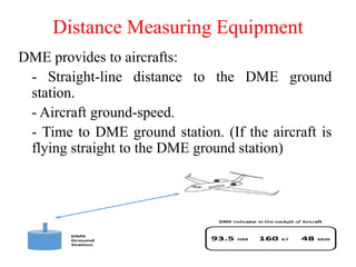
The document outlines the fundamentals of avionics, focusing on various navigation systems including radio navigation, inertial navigation systems, and satellite navigation such as GPS. It describes the roles of pilots in navigation, the principles of Automatic Direction Finders (ADF), Distance Measuring Equipment (DME), and VHF Omni-directional Range (VOR) systems. Key technical details about signal transmission, positioning, and equipment design are also presented to illustrate how these systems assist in aircraft navigation and communication.
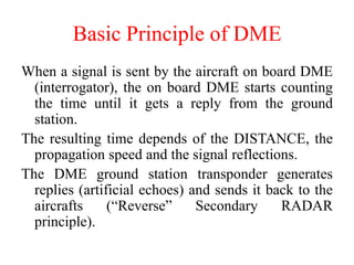
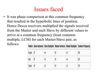
![The Ground station is identified by a Morse (3 or 4
letters) coded tone modulated at 1350 Hz.
DME frequency rang is UHF : 960 MHz to 1215
MHz.
DME have 252 Channels which are separated by 1
MHz .
126 X channel and 126 Y channel.
The ground station signal frequency answer is
always: [interrogator signal frequency] ± 63MHz
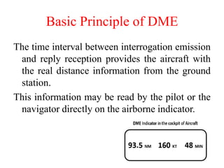
Basic Principle of DME](https://image.slidesharecdn.com/ae8751-unitiv-230615103017-6c9585a8/85/AE8751-UnitIV-pdf-33-320.jpg)