SlideShare a Scribd company logo
▲
89The Journal of The South African Institute of Mining and Metallurgy MAY/JUNE 1997
Introduction to Ausmelt technology
Intensive smelting by the use of a top entry
lance in a slag bath was developed by the
CSIRO in Australia in the early 1970s. Key
motivations in the early work were to recover
values from slags and to smelt tin
concentrates1. This work led to the granting of a
patent to the CSIRO for the Sirosmelt Top Entry
Submerged Lance (TSL) smelting system2.
Dr. J. Floyd, who had headed the team at
CSIRO, founded Ausmelt in 1981. Licences have
been granted by the CSIRO to two companies,
Ausmelt Ltd and Mount Isa Mines Ltd for the
commercialisation of the Sirosmelt system. Both
these companies have introduced further
technological development and both now offer
the system to the market on a world-wide basis.
The latter company has concentrated upon the
processing of copper and lead materials drawing
on its own operational experience.
Figure 1 illustrates the basic features of an
Ausmelt furnace. It is a simple structure with a
high throughput to volume ratio such that
furnace capital cost is usually lower than for
most other furnace designs for similar
throughput. As a broad indication the following
specific throughput ranges apply to the smelting
of a typical copper sulphide concentrate.
Tons/day/m2
of hearth
Reverberatory furnace 4–83,4,5
Flash furnace 9–125
Ausmelt furnace 50–1006
The application of Ausmelt technology
to base metal smelting, now and in the
future
by P.N. Vernon* and S.F. Burks†
Synopsis
Ausmelt top entry submerged lance technology offers a cost-
effective means of carrying out a range of base metal smelting
operations with minimum impact on the environment.
The system is capable of using a range of fuels depending
upon local costs. Due to the intense, localised reaction zone,
high energy efficiency is obtained and the physical size of the
plant is relatively small compared to that of most competing
technologies. Capital cost can thereby be minimised. The
furnace is well enclosed, such that fugitive emissions and
ingress of diluting air to the gas stream are both minimised.
The oxygen potential in the slag can be varied over a wide
range such that the system can be applied in both oxidising
and reducing duties.
Following a general description of the technology, the paper
discusses Ausmelt plants already in operation. The application
of the technology for the provision of additional smelting
capacity, for the improvement of converting operations and for
slag cleaning is then described. A brief explanation of how
these processes could be applied at southern African smelters is
given and the paper closes with an assessment of novel
Ausmelt applications for this geographical region, such as zinc
recovery from sulphides.
* Ausmelt Consultant, 1 Midhurst Way,
Constantia, 7800.
† PGM and Base Minerals, Bateman Minerals &
Industrial Limited, P.O. Box 25937,
East Rand, 1462.
© The South African Institute of Mining and
Metallurgy, 1996. SA ISSN 0038–223X/3.00 +
0.00. First presented at the SAIMM Colloquium:
Trends in Base Metals Smelting and Refining
Apr. 1997.
Figure 1—Cutaway diagram of an Ausmelt furnace
The application of Ausmelt technology to base metal smelting
The furnace structure consists typically of a vertical
steel cylinder, water cooled on the outside and lined
with a refractory suitable for the application. The roof
of the furnace, which may or may not be water cooled,
is normally an inclined cone leading to the off-gas duct
system. The lance, which is the subject of various
patents, enters through a port in the centre of the roof
and is suspended from a suitable hoist system. In
normal operation the tip of the lance is submerged in
the slag bath such that violent splashing occurs. The
splashing provides conditions such that rapid heat and
mass transfer take place between the slag, the feed and
the products of combustion. In this way high energy
efficiency is obtained, thus minimising operating cost.
The patented7 shrouded lance used in Ausmelt’s
technology allows injection of air into the region above
the bath in which a cascade of slag provides excellent
conditions for recovering energy to the bath from post
conduction of metal vapours, carbon monoxide,
hydrocarbon gases, etc, which are generated by
reactions in the bath.
The fuel may be coal, oil or gas depending on site-
specific costs. The combustion gas can be natural, or
oxygen enriched, air. The fuel to oxygen ratio at the
lance tip are readily controllable, as are the reactions in
the bath. At one extreme the system has been operated
at temperatures high enough and oxygen potentials
low enough to reduce iron from oxides of iron. At the
other extreme it has been operated at temperatures as
low as 800o
C and oxygen potentials high enough to
cupel lead from silver. Solid feed normally enters
through a second port in the roof. Where appropriate,
molten material can be introduced via a launder and
weir through the side wall. The furnace may be
operated continuously or in batch mode. In the latter
case, it is possible to carry out a series of operations
sequentially in the same vessel, for example smelting
at close to neutral conditions, converting under
oxidising conditions followed by slag cleaning under
reducing conditions. Alternatively these operations can
be carried out in two or more furnaces in series. This
opens important opportunities for the design of
relatively low capital cost smelting circuits. Mounsey
provides details of such applications for copper
smelting at widely different throughputs8.
Technology applications in non-ferrous metal
smelters
General
The discussion which follows concentrates almost
entirely on nickel, copper and platinum group metal
smelters. The reason for this is quite simple: most non-
ferrous metal smelters in southern and central Africa
are involved in the recovery of these metals. Regional
experience of and interest in base metal pyrometallurgy
is therefore quite naturally focused on these metals.
There are four important potential areas of application
of Ausmelt technology.
Additional smelting capacity
As discussed by Floyd9, Ausmelt technology employs a
pneumatic bath smelting technique. This is illustrated
in Figure 2. It has the following characteristics:
➤ Temperature and concentration differences
between reactants and bath are relatively small,
by comparison with suspension (e.g. flash)
smelting techniques.
➤ The bath is well stirred by the injection of gases
and reactions are therefore very rapid.
➤ Reactions and heat transfer occur predominantly
in a zone above the bath where, due to violent
splashing, slag, charge and other reactants are in
intimate contact.
➤ Coarse feed, up to 100mm in diameter and damp
material can be fed to the furnace because solids
have a long residence time in the bath, compared
with suspension smelting.
➤ By altering the composition of feed solids, fluxes,
fuels and gases, a very wide range of different
process conditions can be generated in the
furnace, from highly reducing right through to
highly oxidising.
These characteristics are quite different from those of
alternative high intensity techniques which utilise
suspension smelting. There are three main reasons
why Ausmelt is often the selected technology when
smelters expand.
Minimal modifications to feed and gas handling
systems
In Southern Africa, most existing smelters use either
submerged arc electric furnaces or coal-fired
reverberatory furnaces. Historically, feed preparation
has been relatively rudimentary, with damp concentrate
being fed to the furnace without preliminary calcining
or drying to zero moisture10,11,12. Oxygen enrichment
has not been widely used and offgas flowrates are high.
In consequence, the addition of an Ausmelt furnace to
an existing smelter in order to boost production will
often require minimal modification to the existing feed
system, fuel supply or gas handling equipment.
▲
90 MAY/JUNE 1997 The Journal of The South African Institute of Mining and Metallurgy
Figure 2—Comparison of heat and mass transfer for bath smelting and
suspension smelting after Floyd9
CGTG
T3 ABOVE BATH REACTION BETWEEN BATH
DROPLETS AND GAS
REACTION AND
HEAT TRANSFER
AT SURFACE OF
BATH
INJECTED GAS
VOLUME
OXIDATION OR
REDUCTION
REACTION AND
HEAT TRANSFER
AT LIQUID/GAS
INTERFACE
REACTION AND HEAT
TRANSFER AT SOLID LIQUID
PARTICLE SURFACE
REACTION
AND HEAT
TRANSFER
TO BATH
REACTION IN
GAS
INJECTED
GAS + SOLIDS
TO LIQUID
ZONE
GAS PHASE
SLAG PHASECBTB
C1T1
C2T2
REACTION WITHIN BATH
BATH SMELTING
SUSPENSION SMELTING
GAS PHASE
Flexibility of metallurgical operation
In the Ausmelt furnace, there are several distinct
reaction zones, which are illustrated in Figure 3. The
types of reactions illustrated all occur in the case of
smelting a high iron sulphide feed to form a matte or
alloy and an iron-rich slag.
➤ At the mouth of the lance, combustion and
oxidation reactions take place in the slag phase,
in a very limited zone which does not penetrate
the bath to a significant extent. During gas rise,
oxidation occurs according to the reactions:
2FeO(slag) + CO2(gas) → Fe2O3(slag)+ CO(gas) [1]
and
2FeO(slag) + 1
/2O2(gas) → Fe2O3(slag). [2]
➤ In the dynamic interfacial and splash zone a
number of smelting and reducing reactions occur:
FeS(feed) + 3Fe2O3 (slag) → 7FeO(slag) + SO2(gas) [3]
MS(feed) + 2MO(slag) → 3M)(metal) + SO2(gas) [4]
MS(feed) + 3Fe2O3(slag) → MO(slag)
+ 6FeO(slag) + SO2(gas) [5]
C(reductant) + Fe2O3(slag) → 2FeO(slag) + CO(gas) [6]
C(reductant) + MO(slag) → M(metal) + CO(gas) [7]
CO(gas) + Fe2O3(slag) → 2FeO(slag) + CO2(gas) [8]
CO(gas) + MO(slag) → M(metal) + CO2(gas) [9]
CO2(gas) + C(reductant) → 2CO(gas) [10]
➤ Above the bath, splashed slag will react with the
gas components rising from the bath, and
afterburning reactions to remove CO, H2 and coal
volatiles from the waste gases will also occur.
➤ Metal or matte droplets formed at the slag surface
will continue to react as they fall through the
slag, and then at the slag : matte interface. The
interface reactions can be accelerated by lowering
the lance. As the metal or matte droplets fall
further they enter a small quiescent zone at the
bottom of the furnace which aids matte/slag
separation.
Because of the multiple reaction zones, the Ausmelt
furnace can be used for a large number of different
pyrometallurgical processes. As far as basic smelting
operations are concerned, Ausmelt can, in theory, be
used to smelt high grade sulphide concentrates autoge-
nously, or increasing amounts of fuel can be added to
smelt materials containing less sulphur or even no
sulphur at all. It is also possible to generate mattes
with varying iron and sulphur contents, making it
possible to assist the subsequent converting operation
as required.
Small ‘footprint’ of Ausmelt furnaces
The third reason why Ausmelt is often favoured for
smelter expansions is the small floor space needed for
an Ausmelt installation by comparison with an
alternative type of furnace with the same smelting
capacity. As noted previously, the specific smelting rate
per square metre of hearth area is an order of
magnitude greater for an Ausmelt furnace than for a
reverberatory unit. In most smelters, additional
buildings and ancillary equipment are added over a
period of time, crowding the original access areas,
utilising expansion allowances for a different purpose
from that originally intended, and generally compli-
cating the life of the plant operators. In many old
smelter plants, it is often extremely difficult to
implement further modifications in the available space.
Ausmelt generally offers a distinct advantage in such
cases since the main constraint on an Ausmelt instal-
lation is available height rather than floor space.
Converting
The following fundamental reactions are involved in
converting furnace mattes containing copper, iron,
sulphur as well as (in some cases) nickel and cobalt:
2FeS(matte) + 3O2(gas) → 2FeO(slag) + 2SO2(gas) [11]
6FeO(slag) + O2(gas) → 2(Fe2O3.FeO)(slag) [12]
2FeO(slag) + SiO2(flux) → (FeO)2SiO2(slag) [13]
3(Fe2O3.FeO)(slag)+ FeS(matte)
+ 5SiO2 (flux) → 5(FeO)2SiO2(slag) [14]
The iron in the furnace matte is therefore removed in a
fayalite slag, while sulphur is oxidised to sulphur dioxide
gas. Converter matte or blister copper are the desired
products containing the metal values.
The standard converting unit throughout the copper and
nickel industries has been the Peirce-Smith converter for
many decades. This tilting, cylindrical converter is very
robust and some steel shells have probably been in use for
close to fifty years. However, the characteristics of the unit
process, as listed, demonstrate its disadvantages:
➤ Tuyères are used to introduce air into the converter.
Severe refractory wear occurs along the line of the
tuyères, necessitating the replacement of at least this
portion of the brick lining after only a few months.
➤ The converting operation is highly exothermic. It is
therefore necessary to add cold solid material to the
converter (reverts and flux), to remove as much heat
as possible in waste gas, and to interrupt the
converting operation periodically in order to keep the
temperature down.
▲
91The Journal of The South African Institute of Mining and Metallurgy MAY/JUNE 1997
The application of Ausmelt technology to base metal smelting
FUEL & AIR
FUMEFEED COAL & FLUX
AFTER BURNING ZONE
FROZEN SLAG LAYER
TO PROTECT LANCE
SMELTING AND
REDUCING ZONE
METAL/MATTE
TAPHOLE
COMBUSTION AND
OXIDIZING ZONE
QUIESCENT ZONE
SLAG
TAPHOLE
Figure 3—Reaction regimes within the Ausmelt furnace
The application of Ausmelt technology to base metal smelting
➤ The tuyère pipes block rapidly and have to be
kept clear by punching frequently with a rod.
➤ The operation is batch in nature, with ladles of
molten material being charged to and removed
from the converter at regular intervals. The large
number of materials handling operations needed
naturally imposes a limit upon process efficiency,
and the transfer of molten matte in open ladles
results in significant loss of sulphur dioxide in
fugitive emissions, constituting an environmental
hazard.
➤ A considerable amount of cold air leaks into the
converter waste gas system at the open junction
between the converter mouth and the waste gas
hood. This increases the flowrate and reduces the
sulphur dioxide concentration of gas to the
sulphuric acid plant which is usually provided to
treat gas from the converting operation.
➤ In order to minimise fugitive emissions of
sulphur dioxide from the converter mouth,
secondary hooding, with dedicated air fans, has
been retrofitted to many converting operations as
environmental emission standards have become
stricter. Secondary emission capture systems
collect very large volumes of cool gas containing
low concentrations of sulphur dioxide. It is
difficult and costly to remove the sulphur dioxide
from this type of gas stream using standard
scrubbing techniques, and the treatment and
discharge to atmosphere therefore presents a
problem. Furthermore, a solid effluent disposal
problem is created.
➤ By design, Peirce-Smith converters are highly
oxidising process units. While they are effective
in removing iron and sulphur from furnace matte,
their inflexibility causes some problems when
converting nickel/copper sulphide mattes. These
problems mainly arise as a consequence of the
downstream refining processes, which usually
require the converter matte to contain low iron
(< 2%) or low sulphur (< 10%) content, or both.
As iron content decreases, cobalt begins to
oxidise and is transferred from matte to slag13, 14,
15. As sulphur concentration decreases, solid
nickel oxide reports to the slag in the converter.
This greatly increases slag viscosity and makes
matte : slag separation less effective. In neither
case is it possible to reverse these reactions in the
oxidising environment of the converter and it is
therefore necessary to transfer converter slag to
another vessel in order to carry out a slag
cleaning operation.
A number of pyrometallurgical technologies have
been proposed over the past few years as possible
replacements for Peirce-Smith converters. Ausmelt is
one of these. In a converting application, it would have
the following advantages over the conventional units:
➤ The oxidising reactions can be controlled more
effectively by altering the composition of the
lance gas.
➤ The operation can tolerate wide fluctuations in
furnace matte (feed) composition since the unit
can be operated as a smelting furnace as well as a
converter.
➤ Refractory life should be better than in a Peirce-
Smith converter. Even in small Ausmelt units
involving high temperatures and multiple semi-
batch processes, refractory life of about 5 months
has been demonstrated in normal operation.
➤ Either molten, or wet granulated solid furnace
matte can be charged to the converting furnace,
and it can be operated in either batch or
continuous mode. Excellent control of the
temperature in the unit and of the speed and
completeness of reaction is therefore possible.
➤ The conventional converter aisle and overhead
gantry cranes could in theory be eliminated, if
molten transfer is no longer required. Although it
is difficult to imagine that an existing converter
aisle could be scrapped, new smelters could
certainly be constructed with provision for
continuous transfer of furnace matte in molten or
solid form from furnace to converter. This is to be
employed at the Zhong Tiao Shan smelter
discussed later in this paper.
➤ The waste gas from an Ausmelt converter will
probably contain greater than 10% sulphur
dioxide by volume at a temperature of about
1300o
C. The potential exists to produce more
sulphuric acid than can be achieved using Peirce-
Smith converters, because of the greatly reduced
dilution with cold air.
➤ There is very little leakage of gas either into or
out of an Ausmelt furnace. Secondary waste gas
hooding is not normally necessary.
➤ Cobalt and nickel losses to slag can be controlled
more effectively both by limiting the oxidation
potential during the converting operation and by
carrying out a batch slag reduction cycle
following converting (elaboration follows).
Slag reduction
During smelting of copper and nickel sulphides, most
metal losses occur because of entrainment of sulphides
in the slag. This is generally addressed by incorpo-
rating a settling zone into one end of the furnace. In
the prevailing quiescent conditions in this zone, matte
separates effectively from slag and collects in the
bottom of the furnace, allowing a discard slag to be
generated. Alternatively, slag or a mixture of matte and
slag may be transferred from the reaction vessel to a
dedicated settling furnace, with the same objective.
There is however a second, chemical, mechanism
by which slag losses occur. During converting a
significant percentage (50–100%) of cobalt in furnace
matte is oxidised into the converter slag, along with a
small percentage of copper and nickel12,13,14.
According to Matousek13, the partition of cobalt
and iron between matte and slag in various smelting
and converting operations can be represented
graphically as shown in Figure 4. The Figure shows
▲
92 MAY/JUNE 1997 The Journal of The South African Institute of Mining and Metallurgy
quite clearly that while cobalt is recovered effectively to
matte during neutral or reducing smelting operations,
significant losses to slag occur under oxidising
conditions.
There are two possible methods of increasing
overall cobalt recovery in smelters which have
converting operations. Firstly, converter slag in nickel
smelters can be reduced in the smelting or slag
cleaning furnace, from which the furnace matte is
recycled to converting. Cobalt gradually accumulates in
the smelter circuit. If the cycle is always operated
successfully then the cobalt eventually leaves the
circuit in the converter matte. This type of circuit is,
however, unforgiving of operational disturbances,
which usually result in cobalt reporting to the discard
furnace slag. It is also inapplicable in the case of copper
smelters, in which blister copper completely free of
cobalt is produced, and all cobalt in the smelter feed is
lost to discard slag.
The second method of recovering cobalt from slags
is to produce a secondary alloy or matte in the slag
cleaning furnace, by reducing the cobalt (and iron)
oxide either with carbon or a sulphide such as pyrite.
In this case, a product containing most of the cobalt
from the converter slag is certainly generated, but it
often contains at least 50% iron.16 This material is not
suitable for feeding to a conventional base metal
refinery. It requires a hydrometallurgical process
tailored to the removal of iron in order to generate a
marketable cobalt product.
Ausmelt technology is suited to both of the slag
reduction processes previously described. In smelters
using an Ausmelt furnace as a converter, a batch cycle
can be set up in which the same furnace will be used,
firstly to convert furnace matte and then subsequently,
to reduce cobalt from the converter slag. At the end of
the reduction phase of the cycle, matte or alloy will be
left in the furnace, a new batch of furnace matte will be
added, and another converting phase will commence.
Periodically, matte or alloy from the reduction furnace
will be removed as a separate intermediate product.
In a smelter where an Ausmelt furnace is retrofitted
solely as a slag cleaning unit, it will operate in
continuous mode. The final control over oxidising
potential which can be achieved in an Ausmelt furnace
means that it can be used to produce either matte or
alloy, and can process converter slag within a fairly
wide composition range.
In general16 the reactions to be expected are:
CoO(slag) + Fe(alloy) → Co(alloy) + FeO(slag) [15]
and
CoO (slag) + FeS (matte) → CoS (matte) + FeO (slag). [16]
Some of the advantages of an Ausmelt furnace in
this application compared with a slag resistance electric
furnace are listed below:
➤ Energy supply is independent of slag
composition. The slag chemistry can therefore be
optimised to recover metals rather than to obtain
the best electrical
characteristics.
➤ Temperature is near to constant through the bath,
and can be increased by the use of fuel in order to
reduce slag viscosity and density.
➤ The furnace is much smaller and possibly less
expensive to maintain.
Sulphur Capture
As noted earlier, Peirce-Smith converter operations lose
a significant percentage of the sulphur entering the
converting circuit in furnace matte as fugitive
emissions of sulphur dioxide. There are two sources of
fugitive emissions: open matte ladles, and the open
mouth of the converter. It is both difficult and
expensive to reduce these emissions to any significant
degree, and at best it is likely that secondary hoods
will simply vent the dilute gas through a tall stack into
the atmosphere. As environmental legislation becomes
stricter, it seems inevitable that Peirce-Smith
converters will gradually be replaced with more modern
units. Quite apart from the metallurgical benefits of the
Ausmelt process, an Ausmelt furnace used in a
converting operation will certainly recover more
sulphur than conventional converters, since both
mouth leakage and losses from molten transfer will be
reduced. In principle, ladle transfer could be completely
eliminated from new smelters.
Ausmelt furnaces, because they have an
independent fuel source and can therefore be operated
at temperatures of greater than 1600o
C under
controlled conditions, can also be used to desulphurise
converter matte17. Sulphur content of nickel–copper
mattes can be reduced to 6–10% or even to about 2%.
This is sometimes a requirement of the downstream
hydrometallurgical operation. By removing the sulphur
in the pyrometallurgical step, it can be converted to
sulphuric acid or sulphur which can be used for
leaching or can be sold. Conversely, in the refinery,
sulphides will dissolve to form sulphuric acid which
will then have to be neutralised, often using expensive
reagents such as caustic soda.
Existing Ausmelt operations and current
projects
Ausmelt plants in regular commercial operation are
shown in Table I.
▲
93The Journal of The South African Institute of Mining and Metallurgy MAY/JUNE 1997
The application of Ausmelt technology to base metal smelting
Figure 4—Cobalt in pyrometallurgical systems after Matousek13
SLAG, 100 x (Co / Fe)
CONVERTER CYCLE
REVERBERATORY FURNACE
FLASH FURNACE
ELECTRIC FURNACE
FURNACE MATTE, 100 X (Co / Fe)
The application of Ausmelt technology to base metal smelting
Example two in that table illustrates the application
of an Ausmelt furnace to close the circuit at a nickel
refinery, as described by Markham, Mwenye and
Vernon18. The objective of the operation is to partially
de-sulphidise the residue from an Outokumpu
atmospheric leach process down to 5–6% sulphur, at
which level it is suitable for grinding and releaching.
The existence of the Ausmelt furnace allows this
refinery to offer a comprehensive custom smelting and
refining capability for low sulphur nickel-copper alloy.
Example four in Table I is the first application of
Ausmelt technology for the converting of copper
sulphide to blister copper. The feed material is a copper
sulphide residue from the non-oxidative pressure
leaching of nickel-copper sulphides. Schwarz and
Richardson describe the rationale for the pyrometal-
lurgical treatment of this residue at Bindura19. The
application of Ausmelt technology followed from that.
The residue is smelted and the resultant molten matte
is then treated under oxidising conditions to convert
the sulphur to sulphur dioxide and the copper to
blister. The blister copper is tapped into a ladle and
transferred to an anode furnace. The slag remaining in
the furnace is high in oxidised copper. Conditions at
the lance are then adjusted and lump coal is added to
reduce that copper. A low copper, disposable slag is
then tapped. Platinum group metals are recovered in
anode slimes when the anode copper is refined.
The process in example five was jointly developed
by Ausmelt and Korea Zinc and, for the first time,
provides a viable solution satisfying all environmental
needs, to the problem of treatment of leach residues in
the zinc industry. The role that Ausmelt technology
plays in the overall Korea Zinc Process is described by
Choi20.
Table II shows plants that are either being commis-
sioned or which are under construction. Items nine and
ten are examples of the replacement of older
technology (sinter plants and blast furnaces) by a
single advanced, environmentally acceptable, item of
equipment. A feature of the design of these plants is
▲
94 MAY/JUNE 1997 The Journal of The South African Institute of Mining and Metallurgy
Table II
Plants being Commissioned or Constructed
8. Ghatsila, India Hindustan Copper Ltd 72 Precious metals In progress
anode slimes
9. Nordenham, Germany Metaleurop 122 000 Primary & secondary In progress
lead materials
10. Tsumeb, Namibia Gold Fields of 120 000 Primary & revert In progress
South Africa lead materials
11. Zhong Tiao Shan, Peoples CNIEC 200 000 Primary copper June 1998
Republic of China concentrates
12. Portland, Alcoa of Australia 12 000 Spent potlining June 1997
Victoria Australia
Table I
Ausmelt Commercial Plants
Location Client Feed Rate Feed Type Commissioning
Tonnes/Yr Date
1. Pt Pirie, Australia Broken Hill 1500 Lead/Silver retort 1990
Associated Smelters metal
2. Eiffel Flats, Zimbabwe Rio Tinto Zimbabwe 7500 Cu/Ni residue 1992
3. Onsan, Korea Korea Zinc Co. Ltd. 90 000 Pb/Zn slag 1992
4. Bindura, Zimbabwe Anglo American Corp. 12 000 Copper Sulphide residue April 1995
5. Onsan, Korea Korea Zinc Co. Ltd 120 000 Zn residue August 1995
6. Hackenohe, Japan Mitsui Mining and 100 000 Zn/Pb slag 1994
Smelting Co.
7. Pisco, Peru Funsur/Minsur SA 30 000 Tin Concentrates March 1996
Figure 5—Two-furnace copper smelting
CONCENTRATES,
FLUXES AND FUEL
SMELTING
FURNACE
RECYCLE
FUME
CONVERTING
FURNACE
GRANULATION
BLISTER COPPER
SETTLER
GRANULATION
DISCARD SLAG
MATTE
MATTE
FLUXES
CONVERTER SLAG
GRANULATED CONVERTER SLAG
the wide range of different feed materials that can be
accommodated within the same furnace. Some of the
many different operating procedures possible are
described by Short, Sutton and Swayn21.
Example eleven, the Zhong Tiao Shan copper
smelter, is the first application of top submerged
lancing technology to all of the steps required in copper
smelting in a single plant and as such is a landmark in
smelting development. Figure 5 is a simplified block
flow diagram of this plant, which is at present under
construction. The chemistry of the process is no
different from that in any other copper smelter as
described earlier. The most important feature of the
plant is the transfer of the primary smelting furnace
matte, via a settler, to the converter by launder rather
than ladles. An alternative routing for that matte is to
granulation such that matte can be stockpiled. In this
way the smelting and converting operations are
decoupled, so that smelting can continue steadily
throughout the converting cycle and also during
converter downtime. Converter slag is granulated for
return to the smelting furnace, again eliminating the
use of ladles. This plant will produce 35 000 tonnes per
year of blister copper from 200 000 tonnes per year of
concentrate.
Potential new southern African applications
The following section is based entirely on literature
references, not on communication of any kind with the
operating companies potentially concerned.
Platinum Group Metal (PGM) smelters
Mostert and Roberts11 described the operation of the
Waterval Smelter of Rustenburg Platinum Mines in
1973. The following key points are of relevance to this
paper:
➤ The charge system at that time incorporated
partial drying to 7% moisture followed by pelleti-
sation and further drying to 2% moisture. This
would be ideal feed for an Ausmelt furnace.
➤ The furnace operation did not include a slag
reduction process. Two mechanisms for recovery
of metal (nickel, copper, platinum group metals
and cobalt) returned from the converter to the
furnace would therefore have existed. Firstly,
metals in the form of entrained matte sulphides
or alloys would be recovered to some extent, by
settling to allow matte: slag separation by density
difference. Secondly, metals present in oxides
would be partially reduced by iron sulphide in the
feed to the smelting furnace. It should be noted
that settling in this type of operation is only
moderately effective because of high slag
viscosity resulting from the presence of
magnetite. Reduction of oxides is quite effective
in the case of nickel and copper, but cobalt oxide
minerals in converter slag generally report to
furnace discard slag unless a specific reduction
process is implemented.
➤ The furnace gas flowrates were very high,
resulting in gas with sulphur dioxide concen-
tration of 0.4%. Even the converter gas concen-
tration was reported to drop to 2.5% SO2 from
time to time.
➤ Peirce-Smith converters were used to remove iron
and sulphur from the furnace matte.
Ward10 as well as Plasket and Ireland12 and Watson
and Harvey22 described the Western Platinum and
Impala Platinum Smelters in more recent papers.
Fundamentally the process at these smelters was and
is the same as at Rustenburg, and more recent press
releases indicate that this is also true of the Crocodile
River, Northam and Hartley Platinum operations.
Cobalt levels in converter matte have been reported to
be about 0.35% Co compared with corresponding iron
content of about 0.5%22.
All four of the Ausmelt technology applications
discussed earlier could be incorporated in these PGM
smelters. Since there is known to be excess total
electric furnace smelting capacity available, it seems
unlikely that any South African PGM producer will be
planning a smelting expansion in the near future.
However, replacement of Peirce-Smith converters,
converter slag reduction to improve cobalt recovery,
and improved sulphur capture are all measures which
could be investigated profitably by PGM producers.
Should they do so, Ausmelt technology would be a
contender in all cases.
Nkana smelter, Zambia
Press releases have indicated that a very large slag
stock pile at the Nkana smelter is being treated on a
small scale to recover cobalt by slag reduction23.
Current arisings of slag also contain cobalt in
significant quantities. The Nkana smelter utilises coal-
fired reverberatory furnaces fed with damp
concentrate24. The feed and fuel systems could be used
almost without modification to feed an Ausmelt
furnace, which in this case could certainly be
considered as a replacement or supplement for the
ageing reverb furnaces.
A dedicated Ausmelt furnace could be used to treat
dump slag in order to recover cobalt, and Ausmelt
technology could also be used either to replace the
Peirce-Smith converters or to recover cobalt from slag.
Ausmelt carried out testwork on this slag during 1994
and produced matte containing cobalt23.
Other copper smelters
O’Kiep and Palabora25 use reverberatory furnaces which
could possibly be replaced by Ausmelt furnaces both in
order to improve operational efficiency and to improve
sulphur capture. Both of these smelters as well as
Mufulira in Zambia26 and Selebi Phikwe in Botswana27
use Peirce-Smith converters which will eventually be
replaced. It is believed that at least two of the above
operations contain cobalt in sufficient quantities to
warrant a dedicated recovery process. Only Palabora
recovers sulphur dioxide from waste gas by means of a
sulphuric acid plant and a weak gas scrubber. There is
therefore great potential to improve sulphur capture
aided by the use of more modern smelting technology.
▲
95The Journal of The South African Institute of Mining and Metallurgy MAY/JUNE 1997
The application of Ausmelt technology to base metal smelting
In summary, therefore, process improvements
making use of Ausmelt technology are possible at
virtually every copper, nickel and PGM smelter in
Southern Africa. While other technologies could well be
suitable for some of these applications, Ausmelt exhibits
a great deal more flexibility than most technologies. It is
conceivable that three Ausmelt furnaces could be used in
a single smelter for the entirely separate and distinct
activities of smelting, converting and slag reduction. In
all cases these furnaces would achieve high recoveries of
sulphur dioxide befitting a modern smelter.
Zinc sulphide concentrate processing
Most sources of zinc are sulphide deposits in which the
zinc is in association with other sulphides. Most
commonly the sulphides are of lead, copper and iron, but
zinc also associates with lesser, but important quantities
of silver, cadmium, arsenic and other elements. These
sulphides are normally separated, with varying degrees
of success depending upon the mineralogy of the
deposit; by flotation to yield separate lead, copper and
zinc concentrates for distinct downstream treatment.
Zinc metal is produced from sulphide concentrate,
either by the Imperial Smelting Process or, more
commonly, by a roast–leach–electrowinning route. In the
hydrometallurgical route it is necessary to remove
virutally all impurities ahead of electrolysis. In particular
iron must be excluded. A number of methods of
achieving this exist; discussion of which has no place in
this paper, other than to note that these high iron
residues all carry with them substantial quantities of
zinc. The paper by Choi (op. sit.) discusses aspects of
this subject and how Ausmelt technology can be utilised
to deal with these residues.
A completely different approach is also possible. Let
us assume that the concentrate has an analysis of
approximately:
Zinc 55%
Copper 2%
Iron 5%
Sulphur 30%
Let us also assume that high sulphur capture is
essential. Under these circumstances Ausmelt
technology can be used as illustrated in the flowsheet
in Figure 6.
Conditions in the primary smelting furnace are
mildly oxidising such that sulphur is driven off as SO2,
copper and iron are dissolved in the slag as oxides, and
lead (as well as other volatile metals) are collected in
the fume. The zinc enters the slag up to a concen-
tration of about 20% and the remainder leaves the
furnace as zinc oxide fume.
In the second furnace the temperature is increased
to about 1350o
C and coal is added to reduce the
oxygen potential in the slag. Under these conditions
the zinc is driven out of the slag as the metal. It is
oxidised in the freeboard of the furnace by secondary
air introduced down the lance shroud pipe. The heat
from the strongly exothermic reaction
Zn(fume) + 1
/2O2(gas)→ZnO(fume) [17]
is partially recovered in the bath by radiation and in
the spashing action. The zinc level in the final discard
slag is likely to be determined economically, but can be
less than 1%.
Advantages of this process route are:
➤ Iron is separated from the zinc at the front end of
the process.
▲
96 MAY/JUNE 1997 The Journal of The South African Institute of Mining and Metallurgy
Figure 6—Process flowsheet for smelting of zinc concentrates
FUEL
40% OXYGEN ENRICHED AIR
CONCENTRATES FLUXES
REDUCTANT COAL
WASTE HEAT
BOILER
FUEL
AIR
ELECTROSTATIC
PRECIPITATOR
SULPHURIC ACID
PLANT
STACK
BAGHOUSE
ACID
GAS
TO STACK
ZINC FUME ZINC FUME
SPENT ELECTROLYTE
LEACHING
REDUCTION
SMELTING
ELECTROWINNING
ZINC
CATHODES
MATTE TO
COPPER SMELTER
DISCARD
SLAG
REDUCTANT
COAL
SLAG
RESIDUES
SOLUTION
PURIFICATION
WASTE HEAT
BOILER
➤ High concentration of SO2 results in the feed to
the acid plant.
➤ Smaller zinc oxide leaching and solution purifi-
cation facilities are required than in a
roast–leach–electrowinning plant of similar capacity.
Application to a bulk zinc-copper concentrate
A logical development from the zinc concentrate treatment
described above is to eliminate the need for differential
flotation and to make a single concentrate that might have
the analyses:
Zinc 45%
Copper 10%
Iron 5%
Sulphur 30%
In this case the plant approaches the copper smelter
discussed earlier in this paper combined with zinc fuming.
The flowsheet shown in Figure 7 applies.
Conclusions
The paper has described some of the present applications of
Ausmelt technology in base metals smelting and refining
and has identified some of the potential applications for the
future.
Process improvements making use of Ausmelt
technology are possible at virtually every copper, nickel and
PGM smelter in southern Africa. While other technologies
could well be suitable for some of these applications,
Ausmelt exhibits a great deal more flexibility than most
techniques. It is conceivable that three Ausmelt furnaces
could be used in a single smelter for the entirely separate
and distinct activities of smelting, converting and slag
reduction. In all cases these furnaces would achieve high
recoveries of sulphur dioxide befitting a modern smelter.
Ausmelt technology is also very applicable in South
Africa for the processing of zinc sulphide concentrates. A
zinc oxide product containing little or no iron can be
generated. While further hydrometallurgical processing is
required, the impurity removal process is simpler than that
required in existing roast–leach–electrowin or pressure
oxidation–electrowin operations.
Ausmelt and Bateman have a collaborative agreement
applicable in several countries under which it is possible to
provide a comprehensive service for the design and
construction of complete plants. The two companies have
co-operated since 1991 on the production of cost estimates
and studies for a number of projects in southern Africa and
elsewhere.
References
1. FLOYD, J.M. Metallurgical Applications of High Temperature Submerged
Combustion, Paper to Institute of Fuels Conference, Adelaide, South
Australia, Nov. 1974. 12 pp.
2. FLOYD, J.M. Submerged injection of gas into liquid pyrometallurgical bath,
US Patent No. 4 251 271, 17 Feb. 1981.
3. MCDONALD, A. and VERHELST, D. Pyrometallurgical operations at Hudson
Bay Mining and Smelting Co. Ltd. CIM Bulletin, vol 87. No. 984. 1994.
pp. 97–102.
4. CASLEY, G.E., MIDDLIN, J., and WHITE, D. Recent development in
reverberatory furnace and converter practice at the Mount Isa Mines
copper smelter. Extractive Metallurgy of Copper, Chap. 6. 1976.
pp. 117–138.
5. MECHEV, V.V. On status and trends of copper industry development in the
U.S.S.R. Copper 91—Cobre 91, vol. IV. 1991. pp. 91–105.
6. FOUNTAIN, C.R., TUPPURAINEN, J.M.I.,WHITWORTH, N.R., and WRIGHT, J.K. The
Paul Queneau International Symposium—Extractive Metallurgy of Copper,
Nickel and Cobalt. vol. II. X. C.A. Landoldt, (ed.). TMS, Warrendale, PA.
1993. pp. 1461–1473.
7. FLOYD, J.M. Top submerged injection with shrouded lance International
Patent Application WO91/05214, 18 Apr. 1991.
8. MOUNSEY, E. Economic and technical evaluation of Ausmelt process
systems for copper bearing materials. Cobre 95. 1995.
▲
97The Journal of The South African Institute of Mining and Metallurgy MAY/JUNE 1997
The application of Ausmelt technology to base metal smelting
Figure 7—Process flowsheet for smelting of bulk copper—zinc concentrates
WASTE HEAT
BOILER
FUEL
40% OXYGEN ENRICHED AIR
ELECTROSTATIC
PRECIPITATOR
SULPHURIC ACID
PLANT
BAGHOUSE
WASTE HEAT
BOILER
ZINC FUME ACID
STACK
GAS
GAS
TO STACK
ZINC FUME
RECYCLED
FUME
EVAPORATIVE
COOLER
CONVERTING
BLISTER
COPPER
SLAG RECYCLED
TO SMELTING
FURNACE
AIR
MATTE
FLUX
REDUCTION
DISCARD
SLAG
REDUCTANT
COAL
MATTE TO
COVERTING
FURNACE
CONCENTRATES FLUXES
REDUCTANT COAL
CONVERTER SLAG
RECYCLED FUME
SMELTING
SLAG
FUEL
AIR
ELECTROSTATIC
PRECIPITATOR
The application of Ausmelt technology to base metal smelting
9. FLOYD, J.M. The Paul Queneau International Symposium—Extractive
Metallurgy of Copper, Nickel and Cobalt, vol. TMS, Warrendale, PA. I.
R.G. Reddy and R.N. Weizenbach, (eds.). 1993. pp. 473–488.
10. WARD, V.C. Electric smelting—some process, control and design aspects:
the smelter, Western Platinum Ltd., Marikana, Transvaal, South Africa.
The Metallurgical Society of AIME. 1978. Paper A78–28.
11. MOSTERT, J.C. and ROBERTS, P.N. Electric smelting at Rustenburg Platinum
Mines Limited of nickel-copper concentrates containing platinum group
metals. J. S. Afr. Inst. Min. Metall., Apr. 1973, pp. 290–299.
12. PLASKET, R.P. and IRELAND, D.A. Ancillary smelter operations and sulphuric
acid manufacture at Impala Platinum Limited. J. S. Afr. Inst. Min. Metall.,
Aug. 1976, pp. 1–10.
13. MATOUSEK, J.W. The Paul Queneau International Symposium—Extractive
Metallurgy of Copper, Nickel and Cobalt, vol. I. TMS, Warrendale, PA.
pp. 129–142.
14. GRIMSEY, E.J. The behaviour of cobalt during nickel smelting and
converting. Aus. Inst. Min. Metall. Proceedings, no. 1, 1994, pp. 77–80.
15. GRIMSEY, E.J. The Paul E. Queneau International Symposium—Extractive
Metallurgy of Copper, Nickel and Cobalt, vol I. R.G. Reddy and R.N.
Weizenbach, (eds.). TMS, Warrendale, PA. 1993. pp. 1239–1251.
16. JONES, R.T., HAYMAN, D.A., and DENTON, G.M. Recovery of cobalt, nickel,
and copper from slags, using DC-arc furnace technology. International
Symposium on Challenges of Process Intensification—35th Annual
Conference of Metallurgists. Montreal, Canada. 1996.
17. BALDOCK, B.R., CHARD, I.L., FLOYD, J.M. et al. The Paul Queneau
International Symposium—Extractive Metallurgy of Copper, Nickel and
Cobalt, vol. II. TMS, Warrendale, PA. 1993. pp. 1081–1100.
18. MARKHAM, P., MWENYE, T., and VERNON, P.N. The smelting of nickel-copper
leach residues. XVth CMMI Congress, Johannesburg, SAIMM, vol. II.
1994. pp. 295–302.
19. SCHWARZ, J. and RICHARDSON, M.R. Process options for
modification of the Outokumpu refinery circuit at BSR Ltd. to improve
base and platinum group metal recoveries. African Mining Conference,
Harare. 1991.
20. CHOI, Z.Y. Evolution of iron separation processes in zinc smelting at Korea
Zinc. Iron in Hydrometallurgy, CIM. 1996.
21. SHORT, W.E., SUTTON, D.J., and SWAYN, G.P. Commercial application of
Ausmelt’s top submerged lance technology in the lead industry. Lead into
the future. IMM London. (1996). pp. 193–204.
22. WATSON, G.B. and HARVEY, B G. A common-sense approach to process
improvements to electric smelting of nickel-copper concentrates at Impala
Platinum. Non-Ferrous Pyrometallurgy: Trace Metals, Furnace Practices
and Energy Efficiency. Met. Soc. Of CIMM. 1991. pp. 289–304.
23. BURKS, S.F. Cobalt recovery at Nkana. Bateman Global Review, Nov. 1995.
p. 6.
24. GIBSON, N. Smelting developments at Rhokana Corporation Limited.
Technical Proceedings of the Northern Rhodesia Section Seventh
Commonwealth Mining and Metallurgical Congress, W.G. Watts, (ed.).
Northern Rhodesia Section, IMM. 1961.
25. EDGE, D.A. Copper matte converting practice at Palabora Mining Company.
Copper and Nickel Converters, R.D. Johnson. (ed.). 1979.
26. BLAIR, I.S., HUMPHRISS, J., JOYCE, B.P., and WARNOCK, J.L. The introduction of
electric smelting technology to Mufulira, Zambia. Extractive Metallurgy of
Copper, TMS—AIME, New York. 1976.
27. HALL, R.A. and HIGHCOCK, G.A. On-line developments at the BCL Smelter.
CIM Bulletin, vol. 88, no. 991. 1995. pp. 89–96. ◆
▲
98 MAY/JUNE 1997 The Journal of The South African Institute of Mining and Metallurgy
Cementation Mining has started work on a surface drilling
contract valued at approximately R50 million in the Target
and Sun prospect areas in the Free State Province. The
contract was awarded by Avgold on an open tender basis.
This is the largest deep surface exploratory drilling
project currently underway on the African continent. The
site is located between Allanridge and Bothaville and work
involves drilling 32 holes in 20 months totalling some
70 000 metres. Commencement date was 10 February 1997.
The exploration is the forerunner to the possible
establishment of a major new gold mine. Cementation
Mining carried out preliminary prospect drilling work on the
site in the early 1990s and the current contract includes reef
cuts from some previously drilled holes.
About 15 Sullivan 50 drill rigs with a depth capability of
3 500 to 4 000 metres will be used for this contract. A total
workforce of around 200, including management, will be
employed on site.
‘Deep hole gold exploration has little application
elsewhere in the world. South Africa has experienced an
extremely quiet period in recent years,’ says Jimmy
Erasmus, manager of Cementation Mining’s Drilling
Division. ‘However, we
have kept our fleet of
drill rigs in good order in
case of an opportunity
such as this.’
Erasmus adds that
Cementation Mining’s
drilling operation has
been awarded several
smaller surface drilling contracts by various companies in
the past few months, indicating an upswing in the industry.
‘We have observed increased confidence and activity in the
mining industry since the second half of last year.’
* Issued by: Lynne Hancock Communications, P.O. Box 180
Witkoppen, 2068.
◆
R50 million surface drilling contract for Cementation Mining*
A typical deep hole
exploration drill rig
used by Cementation
Mining
➤

More Related Content

What's hot

Ring formation in kilns
Ring formation in kilnsRing formation in kilns
Ring formation in kilnspradeepdeepi
 
Pem ln 1_mkp
Pem ln 1_mkpPem ln 1_mkp
Pem ln 1_mkp
Dr. M. Kalyan Phani
 
Zinc Metallurgy
Zinc MetallurgyZinc Metallurgy
Zinc Metallurgy
Pushkar Raj Chandna
 
C 18 - steel melting
C   18 - steel meltingC   18 - steel melting
C 18 - steel melting
cpandiv
 
Alternative Iron making processess
Alternative Iron making processessAlternative Iron making processess
Alternative Iron making processess
Indian Institute of Technology (BHU) Varanasi
 
Petcoke for jsw. pradeep
Petcoke for jsw. pradeepPetcoke for jsw. pradeep
Petcoke for jsw. pradeep
pradeepdeepi
 
CON 123 Session 3 - Typical Raw Mix Design
CON 123 Session 3 - Typical Raw Mix DesignCON 123 Session 3 - Typical Raw Mix Design
CON 123 Session 3 - Typical Raw Mix Designalpenaccedu
 
Cementformulae handbook v2
Cementformulae handbook v2Cementformulae handbook v2
Cementformulae handbook v2
cesar hernandez
 
Capitulo IX Concentracion y Purificacion de Soluciones con Oro II.pdf
Capitulo IX Concentracion y Purificacion de Soluciones con Oro II.pdfCapitulo IX Concentracion y Purificacion de Soluciones con Oro II.pdf
Capitulo IX Concentracion y Purificacion de Soluciones con Oro II.pdf
ARLENSCOLY
 
Egyptian tantalum niobium and tin deposits
Egyptian tantalum  niobium and tin depositsEgyptian tantalum  niobium and tin deposits
Egyptian tantalum niobium and tin deposits
Geology Department, Faculty of Science, Tanta University
 
Graphite
GraphiteGraphite
Graphite
saituysal
 
Clinker Liquid Phase
Clinker Liquid PhaseClinker Liquid Phase
Clinker Liquid Phase
RicardoMosci
 
Raw mix characteristics final
Raw mix characteristics  finalRaw mix characteristics  final
Raw mix characteristics finalpradeepdeepi
 
Nickal and its alloys
Nickal and its alloysNickal and its alloys
Nickal and its alloys
Jim Alex
 
Summer internship Bhilai Steel Plant
Summer internship Bhilai Steel PlantSummer internship Bhilai Steel Plant
Summer internship Bhilai Steel Plant
Saurabh Chaudhary
 
EDS softwares INCA and EDAX_EM forum_Yina Guo_May 2016
EDS softwares INCA and EDAX_EM forum_Yina Guo_May 2016EDS softwares INCA and EDAX_EM forum_Yina Guo_May 2016
EDS softwares INCA and EDAX_EM forum_Yina Guo_May 2016
YinaGuo
 
proceso KIVCET.pptx
proceso KIVCET.pptxproceso KIVCET.pptx
proceso KIVCET.pptx
MiguelQuispe79
 

What's hot (20)

Ring formation in kilns
Ring formation in kilnsRing formation in kilns
Ring formation in kilns
 
Pem ln 1_mkp
Pem ln 1_mkpPem ln 1_mkp
Pem ln 1_mkp
 
Zinc Metallurgy
Zinc MetallurgyZinc Metallurgy
Zinc Metallurgy
 
C 18 - steel melting
C   18 - steel meltingC   18 - steel melting
C 18 - steel melting
 
Alternative Iron making processess
Alternative Iron making processessAlternative Iron making processess
Alternative Iron making processess
 
Petcoke for jsw. pradeep
Petcoke for jsw. pradeepPetcoke for jsw. pradeep
Petcoke for jsw. pradeep
 
CON 123 Session 3 - Typical Raw Mix Design
CON 123 Session 3 - Typical Raw Mix DesignCON 123 Session 3 - Typical Raw Mix Design
CON 123 Session 3 - Typical Raw Mix Design
 
Cementformulae handbook v2
Cementformulae handbook v2Cementformulae handbook v2
Cementformulae handbook v2
 
Capitulo IX Concentracion y Purificacion de Soluciones con Oro II.pdf
Capitulo IX Concentracion y Purificacion de Soluciones con Oro II.pdfCapitulo IX Concentracion y Purificacion de Soluciones con Oro II.pdf
Capitulo IX Concentracion y Purificacion de Soluciones con Oro II.pdf
 
Egyptian tantalum niobium and tin deposits
Egyptian tantalum  niobium and tin depositsEgyptian tantalum  niobium and tin deposits
Egyptian tantalum niobium and tin deposits
 
Graphite
GraphiteGraphite
Graphite
 
Clinker Liquid Phase
Clinker Liquid PhaseClinker Liquid Phase
Clinker Liquid Phase
 
Raw mix characteristics final
Raw mix characteristics  finalRaw mix characteristics  final
Raw mix characteristics final
 
Nickal and its alloys
Nickal and its alloysNickal and its alloys
Nickal and its alloys
 
1 yeso 1 e carmen galan
1 yeso 1 e carmen galan1 yeso 1 e carmen galan
1 yeso 1 e carmen galan
 
Summer internship Bhilai Steel Plant
Summer internship Bhilai Steel PlantSummer internship Bhilai Steel Plant
Summer internship Bhilai Steel Plant
 
EDS softwares INCA and EDAX_EM forum_Yina Guo_May 2016
EDS softwares INCA and EDAX_EM forum_Yina Guo_May 2016EDS softwares INCA and EDAX_EM forum_Yina Guo_May 2016
EDS softwares INCA and EDAX_EM forum_Yina Guo_May 2016
 
proceso KIVCET.pptx
proceso KIVCET.pptxproceso KIVCET.pptx
proceso KIVCET.pptx
 
Finmet process
Finmet processFinmet process
Finmet process
 
Igneous processes
Igneous processesIgneous processes
Igneous processes
 

Similar to The Application of Ausmelt Technology

Innovative engineering design in circulating fluid bed technology
Innovative engineering design in circulating fluid bed technologyInnovative engineering design in circulating fluid bed technology
Innovative engineering design in circulating fluid bed technology
Igor Sidorenko
 
1 s2.0-s1877705816004434-main
1 s2.0-s1877705816004434-main1 s2.0-s1877705816004434-main
1 s2.0-s1877705816004434-main
Abderrahim Nadifi
 
Chapter 7 - Coal.pptx
Chapter 7 - Coal.pptxChapter 7 - Coal.pptx
Chapter 7 - Coal.pptx
AkramMusa5
 
Production of ferronickel from nickel laterites in a dc arc furnace
Production of ferronickel from nickel laterites in a dc arc furnaceProduction of ferronickel from nickel laterites in a dc arc furnace
Production of ferronickel from nickel laterites in a dc arc furnacedanadal04
 
210701_mo_ausmelt_tsl_process_brochure_update_lowres.pdf
210701_mo_ausmelt_tsl_process_brochure_update_lowres.pdf210701_mo_ausmelt_tsl_process_brochure_update_lowres.pdf
210701_mo_ausmelt_tsl_process_brochure_update_lowres.pdf
NabilaFatihahR
 
High Speed Infra Red Furnace
High Speed Infra Red FurnaceHigh Speed Infra Red Furnace
High Speed Infra Red Furnace
IJMER
 
Chandan me
Chandan meChandan me
Corex Process in Iron Making
Corex Process in Iron MakingCorex Process in Iron Making
Corex Process in Iron Making
Aditya Singh
 
week 12 lec 56-60.pdf
week 12 lec 56-60.pdfweek 12 lec 56-60.pdf
week 12 lec 56-60.pdf
AmanNigam33
 
Industrial gases supporting natural gas processing
Industrial gases supporting natural gas processingIndustrial gases supporting natural gas processing
Industrial gases supporting natural gas processing
Linde Gas Benelux
 
Reduction in charge requirements of HIsmelt process
Reduction in charge requirements of HIsmelt processReduction in charge requirements of HIsmelt process
Reduction in charge requirements of HIsmelt process
Mainak Saha(मैनक साहा)
 
Rotary kiln
Rotary kilnRotary kiln
Rotary kiln
Aree Salah
 
IRJET- Carbon Particles Removing in Exhaust Gases
IRJET- Carbon Particles Removing in Exhaust GasesIRJET- Carbon Particles Removing in Exhaust Gases
IRJET- Carbon Particles Removing in Exhaust Gases
IRJET Journal
 
Principals of roasting and its types
Principals of roasting and its typesPrincipals of roasting and its types
Principals of roasting and its types
Akshat Chaturvedi
 
RAUTOMEAD TECHNOLOGY FOR CONTINUOUS CASTING OF OXYGEN-FREE COPPER, COPPER-MA...
 RAUTOMEAD TECHNOLOGY FOR CONTINUOUS CASTING OF OXYGEN-FREE COPPER, COPPER-MA... RAUTOMEAD TECHNOLOGY FOR CONTINUOUS CASTING OF OXYGEN-FREE COPPER, COPPER-MA...
RAUTOMEAD TECHNOLOGY FOR CONTINUOUS CASTING OF OXYGEN-FREE COPPER, COPPER-MA...
Rautomead Limited
 
Steel production at compact strip pellet mill
Steel production at compact strip pellet millSteel production at compact strip pellet mill
Steel production at compact strip pellet mill
Home
 
Iron and Steel Making with allied chemical reactions .pptx
Iron and Steel Making with allied chemical reactions .pptxIron and Steel Making with allied chemical reactions .pptx
Iron and Steel Making with allied chemical reactions .pptx
029DevendraKumarSing
 
RAUTOMEAD TECHNOLOGY FOR CONTINUOUS CASTING OF OXYGEN-FREE COPPER AND DILUTE...
RAUTOMEAD  TECHNOLOGY FOR CONTINUOUS CASTING OF OXYGEN-FREE COPPER AND DILUTE...RAUTOMEAD  TECHNOLOGY FOR CONTINUOUS CASTING OF OXYGEN-FREE COPPER AND DILUTE...
RAUTOMEAD TECHNOLOGY FOR CONTINUOUS CASTING OF OXYGEN-FREE COPPER AND DILUTE...
Rautomead Limited
 
00258 corrosion erosion corrosion protection by mo
00258 corrosion  erosion corrosion protection by mo00258 corrosion  erosion corrosion protection by mo
00258 corrosion erosion corrosion protection by mo
Abdelmajid BEN HAMED
 

Similar to The Application of Ausmelt Technology (20)

Innovative engineering design in circulating fluid bed technology
Innovative engineering design in circulating fluid bed technologyInnovative engineering design in circulating fluid bed technology
Innovative engineering design in circulating fluid bed technology
 
1 s2.0-s1877705816004434-main
1 s2.0-s1877705816004434-main1 s2.0-s1877705816004434-main
1 s2.0-s1877705816004434-main
 
Chapter 7 - Coal.pptx
Chapter 7 - Coal.pptxChapter 7 - Coal.pptx
Chapter 7 - Coal.pptx
 
Production of ferronickel from nickel laterites in a dc arc furnace
Production of ferronickel from nickel laterites in a dc arc furnaceProduction of ferronickel from nickel laterites in a dc arc furnace
Production of ferronickel from nickel laterites in a dc arc furnace
 
210701_mo_ausmelt_tsl_process_brochure_update_lowres.pdf
210701_mo_ausmelt_tsl_process_brochure_update_lowres.pdf210701_mo_ausmelt_tsl_process_brochure_update_lowres.pdf
210701_mo_ausmelt_tsl_process_brochure_update_lowres.pdf
 
High Speed Infra Red Furnace
High Speed Infra Red FurnaceHigh Speed Infra Red Furnace
High Speed Infra Red Furnace
 
Advances in SPecail Steels : Super alloy ni and ti alloys
Advances in SPecail Steels : Super alloy ni and ti alloysAdvances in SPecail Steels : Super alloy ni and ti alloys
Advances in SPecail Steels : Super alloy ni and ti alloys
 
Chandan me
Chandan meChandan me
Chandan me
 
Corex Process in Iron Making
Corex Process in Iron MakingCorex Process in Iron Making
Corex Process in Iron Making
 
week 12 lec 56-60.pdf
week 12 lec 56-60.pdfweek 12 lec 56-60.pdf
week 12 lec 56-60.pdf
 
Industrial gases supporting natural gas processing
Industrial gases supporting natural gas processingIndustrial gases supporting natural gas processing
Industrial gases supporting natural gas processing
 
Reduction in charge requirements of HIsmelt process
Reduction in charge requirements of HIsmelt processReduction in charge requirements of HIsmelt process
Reduction in charge requirements of HIsmelt process
 
Rotary kiln
Rotary kilnRotary kiln
Rotary kiln
 
IRJET- Carbon Particles Removing in Exhaust Gases
IRJET- Carbon Particles Removing in Exhaust GasesIRJET- Carbon Particles Removing in Exhaust Gases
IRJET- Carbon Particles Removing in Exhaust Gases
 
Principals of roasting and its types
Principals of roasting and its typesPrincipals of roasting and its types
Principals of roasting and its types
 
RAUTOMEAD TECHNOLOGY FOR CONTINUOUS CASTING OF OXYGEN-FREE COPPER, COPPER-MA...
 RAUTOMEAD TECHNOLOGY FOR CONTINUOUS CASTING OF OXYGEN-FREE COPPER, COPPER-MA... RAUTOMEAD TECHNOLOGY FOR CONTINUOUS CASTING OF OXYGEN-FREE COPPER, COPPER-MA...
RAUTOMEAD TECHNOLOGY FOR CONTINUOUS CASTING OF OXYGEN-FREE COPPER, COPPER-MA...
 
Steel production at compact strip pellet mill
Steel production at compact strip pellet millSteel production at compact strip pellet mill
Steel production at compact strip pellet mill
 
Iron and Steel Making with allied chemical reactions .pptx
Iron and Steel Making with allied chemical reactions .pptxIron and Steel Making with allied chemical reactions .pptx
Iron and Steel Making with allied chemical reactions .pptx
 
RAUTOMEAD TECHNOLOGY FOR CONTINUOUS CASTING OF OXYGEN-FREE COPPER AND DILUTE...
RAUTOMEAD  TECHNOLOGY FOR CONTINUOUS CASTING OF OXYGEN-FREE COPPER AND DILUTE...RAUTOMEAD  TECHNOLOGY FOR CONTINUOUS CASTING OF OXYGEN-FREE COPPER AND DILUTE...
RAUTOMEAD TECHNOLOGY FOR CONTINUOUS CASTING OF OXYGEN-FREE COPPER AND DILUTE...
 
00258 corrosion erosion corrosion protection by mo
00258 corrosion  erosion corrosion protection by mo00258 corrosion  erosion corrosion protection by mo
00258 corrosion erosion corrosion protection by mo
 

The Application of Ausmelt Technology

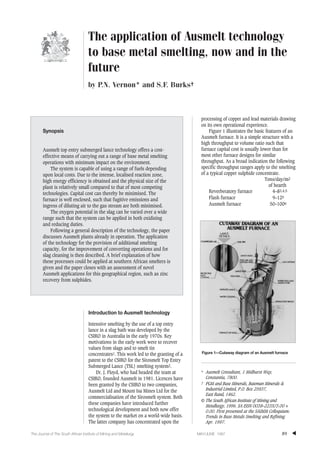
  • 1. ▲ 89The Journal of The South African Institute of Mining and Metallurgy MAY/JUNE 1997 Introduction to Ausmelt technology Intensive smelting by the use of a top entry lance in a slag bath was developed by the CSIRO in Australia in the early 1970s. Key motivations in the early work were to recover values from slags and to smelt tin concentrates1. This work led to the granting of a patent to the CSIRO for the Sirosmelt Top Entry Submerged Lance (TSL) smelting system2. Dr. J. Floyd, who had headed the team at CSIRO, founded Ausmelt in 1981. Licences have been granted by the CSIRO to two companies, Ausmelt Ltd and Mount Isa Mines Ltd for the commercialisation of the Sirosmelt system. Both these companies have introduced further technological development and both now offer the system to the market on a world-wide basis. The latter company has concentrated upon the processing of copper and lead materials drawing on its own operational experience. Figure 1 illustrates the basic features of an Ausmelt furnace. It is a simple structure with a high throughput to volume ratio such that furnace capital cost is usually lower than for most other furnace designs for similar throughput. As a broad indication the following specific throughput ranges apply to the smelting of a typical copper sulphide concentrate. Tons/day/m2 of hearth Reverberatory furnace 4–83,4,5 Flash furnace 9–125 Ausmelt furnace 50–1006 The application of Ausmelt technology to base metal smelting, now and in the future by P.N. Vernon* and S.F. Burks† Synopsis Ausmelt top entry submerged lance technology offers a cost- effective means of carrying out a range of base metal smelting operations with minimum impact on the environment. The system is capable of using a range of fuels depending upon local costs. Due to the intense, localised reaction zone, high energy efficiency is obtained and the physical size of the plant is relatively small compared to that of most competing technologies. Capital cost can thereby be minimised. The furnace is well enclosed, such that fugitive emissions and ingress of diluting air to the gas stream are both minimised. The oxygen potential in the slag can be varied over a wide range such that the system can be applied in both oxidising and reducing duties. Following a general description of the technology, the paper discusses Ausmelt plants already in operation. The application of the technology for the provision of additional smelting capacity, for the improvement of converting operations and for slag cleaning is then described. A brief explanation of how these processes could be applied at southern African smelters is given and the paper closes with an assessment of novel Ausmelt applications for this geographical region, such as zinc recovery from sulphides. * Ausmelt Consultant, 1 Midhurst Way, Constantia, 7800. † PGM and Base Minerals, Bateman Minerals & Industrial Limited, P.O. Box 25937, East Rand, 1462. © The South African Institute of Mining and Metallurgy, 1996. SA ISSN 0038–223X/3.00 + 0.00. First presented at the SAIMM Colloquium: Trends in Base Metals Smelting and Refining Apr. 1997. Figure 1—Cutaway diagram of an Ausmelt furnace
  • 2. The application of Ausmelt technology to base metal smelting The furnace structure consists typically of a vertical steel cylinder, water cooled on the outside and lined with a refractory suitable for the application. The roof of the furnace, which may or may not be water cooled, is normally an inclined cone leading to the off-gas duct system. The lance, which is the subject of various patents, enters through a port in the centre of the roof and is suspended from a suitable hoist system. In normal operation the tip of the lance is submerged in the slag bath such that violent splashing occurs. The splashing provides conditions such that rapid heat and mass transfer take place between the slag, the feed and the products of combustion. In this way high energy efficiency is obtained, thus minimising operating cost. The patented7 shrouded lance used in Ausmelt’s technology allows injection of air into the region above the bath in which a cascade of slag provides excellent conditions for recovering energy to the bath from post conduction of metal vapours, carbon monoxide, hydrocarbon gases, etc, which are generated by reactions in the bath. The fuel may be coal, oil or gas depending on site- specific costs. The combustion gas can be natural, or oxygen enriched, air. The fuel to oxygen ratio at the lance tip are readily controllable, as are the reactions in the bath. At one extreme the system has been operated at temperatures high enough and oxygen potentials low enough to reduce iron from oxides of iron. At the other extreme it has been operated at temperatures as low as 800o C and oxygen potentials high enough to cupel lead from silver. Solid feed normally enters through a second port in the roof. Where appropriate, molten material can be introduced via a launder and weir through the side wall. The furnace may be operated continuously or in batch mode. In the latter case, it is possible to carry out a series of operations sequentially in the same vessel, for example smelting at close to neutral conditions, converting under oxidising conditions followed by slag cleaning under reducing conditions. Alternatively these operations can be carried out in two or more furnaces in series. This opens important opportunities for the design of relatively low capital cost smelting circuits. Mounsey provides details of such applications for copper smelting at widely different throughputs8. Technology applications in non-ferrous metal smelters General The discussion which follows concentrates almost entirely on nickel, copper and platinum group metal smelters. The reason for this is quite simple: most non- ferrous metal smelters in southern and central Africa are involved in the recovery of these metals. Regional experience of and interest in base metal pyrometallurgy is therefore quite naturally focused on these metals. There are four important potential areas of application of Ausmelt technology. Additional smelting capacity As discussed by Floyd9, Ausmelt technology employs a pneumatic bath smelting technique. This is illustrated in Figure 2. It has the following characteristics: ➤ Temperature and concentration differences between reactants and bath are relatively small, by comparison with suspension (e.g. flash) smelting techniques. ➤ The bath is well stirred by the injection of gases and reactions are therefore very rapid. ➤ Reactions and heat transfer occur predominantly in a zone above the bath where, due to violent splashing, slag, charge and other reactants are in intimate contact. ➤ Coarse feed, up to 100mm in diameter and damp material can be fed to the furnace because solids have a long residence time in the bath, compared with suspension smelting. ➤ By altering the composition of feed solids, fluxes, fuels and gases, a very wide range of different process conditions can be generated in the furnace, from highly reducing right through to highly oxidising. These characteristics are quite different from those of alternative high intensity techniques which utilise suspension smelting. There are three main reasons why Ausmelt is often the selected technology when smelters expand. Minimal modifications to feed and gas handling systems In Southern Africa, most existing smelters use either submerged arc electric furnaces or coal-fired reverberatory furnaces. Historically, feed preparation has been relatively rudimentary, with damp concentrate being fed to the furnace without preliminary calcining or drying to zero moisture10,11,12. Oxygen enrichment has not been widely used and offgas flowrates are high. In consequence, the addition of an Ausmelt furnace to an existing smelter in order to boost production will often require minimal modification to the existing feed system, fuel supply or gas handling equipment. ▲ 90 MAY/JUNE 1997 The Journal of The South African Institute of Mining and Metallurgy Figure 2—Comparison of heat and mass transfer for bath smelting and suspension smelting after Floyd9 CGTG T3 ABOVE BATH REACTION BETWEEN BATH DROPLETS AND GAS REACTION AND HEAT TRANSFER AT SURFACE OF BATH INJECTED GAS VOLUME OXIDATION OR REDUCTION REACTION AND HEAT TRANSFER AT LIQUID/GAS INTERFACE REACTION AND HEAT TRANSFER AT SOLID LIQUID PARTICLE SURFACE REACTION AND HEAT TRANSFER TO BATH REACTION IN GAS INJECTED GAS + SOLIDS TO LIQUID ZONE GAS PHASE SLAG PHASECBTB C1T1 C2T2 REACTION WITHIN BATH BATH SMELTING SUSPENSION SMELTING GAS PHASE
  • 3. Flexibility of metallurgical operation In the Ausmelt furnace, there are several distinct reaction zones, which are illustrated in Figure 3. The types of reactions illustrated all occur in the case of smelting a high iron sulphide feed to form a matte or alloy and an iron-rich slag. ➤ At the mouth of the lance, combustion and oxidation reactions take place in the slag phase, in a very limited zone which does not penetrate the bath to a significant extent. During gas rise, oxidation occurs according to the reactions: 2FeO(slag) + CO2(gas) → Fe2O3(slag)+ CO(gas) [1] and 2FeO(slag) + 1 /2O2(gas) → Fe2O3(slag). [2] ➤ In the dynamic interfacial and splash zone a number of smelting and reducing reactions occur: FeS(feed) + 3Fe2O3 (slag) → 7FeO(slag) + SO2(gas) [3] MS(feed) + 2MO(slag) → 3M)(metal) + SO2(gas) [4] MS(feed) + 3Fe2O3(slag) → MO(slag) + 6FeO(slag) + SO2(gas) [5] C(reductant) + Fe2O3(slag) → 2FeO(slag) + CO(gas) [6] C(reductant) + MO(slag) → M(metal) + CO(gas) [7] CO(gas) + Fe2O3(slag) → 2FeO(slag) + CO2(gas) [8] CO(gas) + MO(slag) → M(metal) + CO2(gas) [9] CO2(gas) + C(reductant) → 2CO(gas) [10] ➤ Above the bath, splashed slag will react with the gas components rising from the bath, and afterburning reactions to remove CO, H2 and coal volatiles from the waste gases will also occur. ➤ Metal or matte droplets formed at the slag surface will continue to react as they fall through the slag, and then at the slag : matte interface. The interface reactions can be accelerated by lowering the lance. As the metal or matte droplets fall further they enter a small quiescent zone at the bottom of the furnace which aids matte/slag separation. Because of the multiple reaction zones, the Ausmelt furnace can be used for a large number of different pyrometallurgical processes. As far as basic smelting operations are concerned, Ausmelt can, in theory, be used to smelt high grade sulphide concentrates autoge- nously, or increasing amounts of fuel can be added to smelt materials containing less sulphur or even no sulphur at all. It is also possible to generate mattes with varying iron and sulphur contents, making it possible to assist the subsequent converting operation as required. Small ‘footprint’ of Ausmelt furnaces The third reason why Ausmelt is often favoured for smelter expansions is the small floor space needed for an Ausmelt installation by comparison with an alternative type of furnace with the same smelting capacity. As noted previously, the specific smelting rate per square metre of hearth area is an order of magnitude greater for an Ausmelt furnace than for a reverberatory unit. In most smelters, additional buildings and ancillary equipment are added over a period of time, crowding the original access areas, utilising expansion allowances for a different purpose from that originally intended, and generally compli- cating the life of the plant operators. In many old smelter plants, it is often extremely difficult to implement further modifications in the available space. Ausmelt generally offers a distinct advantage in such cases since the main constraint on an Ausmelt instal- lation is available height rather than floor space. Converting The following fundamental reactions are involved in converting furnace mattes containing copper, iron, sulphur as well as (in some cases) nickel and cobalt: 2FeS(matte) + 3O2(gas) → 2FeO(slag) + 2SO2(gas) [11] 6FeO(slag) + O2(gas) → 2(Fe2O3.FeO)(slag) [12] 2FeO(slag) + SiO2(flux) → (FeO)2SiO2(slag) [13] 3(Fe2O3.FeO)(slag)+ FeS(matte) + 5SiO2 (flux) → 5(FeO)2SiO2(slag) [14] The iron in the furnace matte is therefore removed in a fayalite slag, while sulphur is oxidised to sulphur dioxide gas. Converter matte or blister copper are the desired products containing the metal values. The standard converting unit throughout the copper and nickel industries has been the Peirce-Smith converter for many decades. This tilting, cylindrical converter is very robust and some steel shells have probably been in use for close to fifty years. However, the characteristics of the unit process, as listed, demonstrate its disadvantages: ➤ Tuyères are used to introduce air into the converter. Severe refractory wear occurs along the line of the tuyères, necessitating the replacement of at least this portion of the brick lining after only a few months. ➤ The converting operation is highly exothermic. It is therefore necessary to add cold solid material to the converter (reverts and flux), to remove as much heat as possible in waste gas, and to interrupt the converting operation periodically in order to keep the temperature down. ▲ 91The Journal of The South African Institute of Mining and Metallurgy MAY/JUNE 1997 The application of Ausmelt technology to base metal smelting FUEL & AIR FUMEFEED COAL & FLUX AFTER BURNING ZONE FROZEN SLAG LAYER TO PROTECT LANCE SMELTING AND REDUCING ZONE METAL/MATTE TAPHOLE COMBUSTION AND OXIDIZING ZONE QUIESCENT ZONE SLAG TAPHOLE Figure 3—Reaction regimes within the Ausmelt furnace
  • 4. The application of Ausmelt technology to base metal smelting ➤ The tuyère pipes block rapidly and have to be kept clear by punching frequently with a rod. ➤ The operation is batch in nature, with ladles of molten material being charged to and removed from the converter at regular intervals. The large number of materials handling operations needed naturally imposes a limit upon process efficiency, and the transfer of molten matte in open ladles results in significant loss of sulphur dioxide in fugitive emissions, constituting an environmental hazard. ➤ A considerable amount of cold air leaks into the converter waste gas system at the open junction between the converter mouth and the waste gas hood. This increases the flowrate and reduces the sulphur dioxide concentration of gas to the sulphuric acid plant which is usually provided to treat gas from the converting operation. ➤ In order to minimise fugitive emissions of sulphur dioxide from the converter mouth, secondary hooding, with dedicated air fans, has been retrofitted to many converting operations as environmental emission standards have become stricter. Secondary emission capture systems collect very large volumes of cool gas containing low concentrations of sulphur dioxide. It is difficult and costly to remove the sulphur dioxide from this type of gas stream using standard scrubbing techniques, and the treatment and discharge to atmosphere therefore presents a problem. Furthermore, a solid effluent disposal problem is created. ➤ By design, Peirce-Smith converters are highly oxidising process units. While they are effective in removing iron and sulphur from furnace matte, their inflexibility causes some problems when converting nickel/copper sulphide mattes. These problems mainly arise as a consequence of the downstream refining processes, which usually require the converter matte to contain low iron (< 2%) or low sulphur (< 10%) content, or both. As iron content decreases, cobalt begins to oxidise and is transferred from matte to slag13, 14, 15. As sulphur concentration decreases, solid nickel oxide reports to the slag in the converter. This greatly increases slag viscosity and makes matte : slag separation less effective. In neither case is it possible to reverse these reactions in the oxidising environment of the converter and it is therefore necessary to transfer converter slag to another vessel in order to carry out a slag cleaning operation. A number of pyrometallurgical technologies have been proposed over the past few years as possible replacements for Peirce-Smith converters. Ausmelt is one of these. In a converting application, it would have the following advantages over the conventional units: ➤ The oxidising reactions can be controlled more effectively by altering the composition of the lance gas. ➤ The operation can tolerate wide fluctuations in furnace matte (feed) composition since the unit can be operated as a smelting furnace as well as a converter. ➤ Refractory life should be better than in a Peirce- Smith converter. Even in small Ausmelt units involving high temperatures and multiple semi- batch processes, refractory life of about 5 months has been demonstrated in normal operation. ➤ Either molten, or wet granulated solid furnace matte can be charged to the converting furnace, and it can be operated in either batch or continuous mode. Excellent control of the temperature in the unit and of the speed and completeness of reaction is therefore possible. ➤ The conventional converter aisle and overhead gantry cranes could in theory be eliminated, if molten transfer is no longer required. Although it is difficult to imagine that an existing converter aisle could be scrapped, new smelters could certainly be constructed with provision for continuous transfer of furnace matte in molten or solid form from furnace to converter. This is to be employed at the Zhong Tiao Shan smelter discussed later in this paper. ➤ The waste gas from an Ausmelt converter will probably contain greater than 10% sulphur dioxide by volume at a temperature of about 1300o C. The potential exists to produce more sulphuric acid than can be achieved using Peirce- Smith converters, because of the greatly reduced dilution with cold air. ➤ There is very little leakage of gas either into or out of an Ausmelt furnace. Secondary waste gas hooding is not normally necessary. ➤ Cobalt and nickel losses to slag can be controlled more effectively both by limiting the oxidation potential during the converting operation and by carrying out a batch slag reduction cycle following converting (elaboration follows). Slag reduction During smelting of copper and nickel sulphides, most metal losses occur because of entrainment of sulphides in the slag. This is generally addressed by incorpo- rating a settling zone into one end of the furnace. In the prevailing quiescent conditions in this zone, matte separates effectively from slag and collects in the bottom of the furnace, allowing a discard slag to be generated. Alternatively, slag or a mixture of matte and slag may be transferred from the reaction vessel to a dedicated settling furnace, with the same objective. There is however a second, chemical, mechanism by which slag losses occur. During converting a significant percentage (50–100%) of cobalt in furnace matte is oxidised into the converter slag, along with a small percentage of copper and nickel12,13,14. According to Matousek13, the partition of cobalt and iron between matte and slag in various smelting and converting operations can be represented graphically as shown in Figure 4. The Figure shows ▲ 92 MAY/JUNE 1997 The Journal of The South African Institute of Mining and Metallurgy
  • 5. quite clearly that while cobalt is recovered effectively to matte during neutral or reducing smelting operations, significant losses to slag occur under oxidising conditions. There are two possible methods of increasing overall cobalt recovery in smelters which have converting operations. Firstly, converter slag in nickel smelters can be reduced in the smelting or slag cleaning furnace, from which the furnace matte is recycled to converting. Cobalt gradually accumulates in the smelter circuit. If the cycle is always operated successfully then the cobalt eventually leaves the circuit in the converter matte. This type of circuit is, however, unforgiving of operational disturbances, which usually result in cobalt reporting to the discard furnace slag. It is also inapplicable in the case of copper smelters, in which blister copper completely free of cobalt is produced, and all cobalt in the smelter feed is lost to discard slag. The second method of recovering cobalt from slags is to produce a secondary alloy or matte in the slag cleaning furnace, by reducing the cobalt (and iron) oxide either with carbon or a sulphide such as pyrite. In this case, a product containing most of the cobalt from the converter slag is certainly generated, but it often contains at least 50% iron.16 This material is not suitable for feeding to a conventional base metal refinery. It requires a hydrometallurgical process tailored to the removal of iron in order to generate a marketable cobalt product. Ausmelt technology is suited to both of the slag reduction processes previously described. In smelters using an Ausmelt furnace as a converter, a batch cycle can be set up in which the same furnace will be used, firstly to convert furnace matte and then subsequently, to reduce cobalt from the converter slag. At the end of the reduction phase of the cycle, matte or alloy will be left in the furnace, a new batch of furnace matte will be added, and another converting phase will commence. Periodically, matte or alloy from the reduction furnace will be removed as a separate intermediate product. In a smelter where an Ausmelt furnace is retrofitted solely as a slag cleaning unit, it will operate in continuous mode. The final control over oxidising potential which can be achieved in an Ausmelt furnace means that it can be used to produce either matte or alloy, and can process converter slag within a fairly wide composition range. In general16 the reactions to be expected are: CoO(slag) + Fe(alloy) → Co(alloy) + FeO(slag) [15] and CoO (slag) + FeS (matte) → CoS (matte) + FeO (slag). [16] Some of the advantages of an Ausmelt furnace in this application compared with a slag resistance electric furnace are listed below: ➤ Energy supply is independent of slag composition. The slag chemistry can therefore be optimised to recover metals rather than to obtain the best electrical characteristics. ➤ Temperature is near to constant through the bath, and can be increased by the use of fuel in order to reduce slag viscosity and density. ➤ The furnace is much smaller and possibly less expensive to maintain. Sulphur Capture As noted earlier, Peirce-Smith converter operations lose a significant percentage of the sulphur entering the converting circuit in furnace matte as fugitive emissions of sulphur dioxide. There are two sources of fugitive emissions: open matte ladles, and the open mouth of the converter. It is both difficult and expensive to reduce these emissions to any significant degree, and at best it is likely that secondary hoods will simply vent the dilute gas through a tall stack into the atmosphere. As environmental legislation becomes stricter, it seems inevitable that Peirce-Smith converters will gradually be replaced with more modern units. Quite apart from the metallurgical benefits of the Ausmelt process, an Ausmelt furnace used in a converting operation will certainly recover more sulphur than conventional converters, since both mouth leakage and losses from molten transfer will be reduced. In principle, ladle transfer could be completely eliminated from new smelters. Ausmelt furnaces, because they have an independent fuel source and can therefore be operated at temperatures of greater than 1600o C under controlled conditions, can also be used to desulphurise converter matte17. Sulphur content of nickel–copper mattes can be reduced to 6–10% or even to about 2%. This is sometimes a requirement of the downstream hydrometallurgical operation. By removing the sulphur in the pyrometallurgical step, it can be converted to sulphuric acid or sulphur which can be used for leaching or can be sold. Conversely, in the refinery, sulphides will dissolve to form sulphuric acid which will then have to be neutralised, often using expensive reagents such as caustic soda. Existing Ausmelt operations and current projects Ausmelt plants in regular commercial operation are shown in Table I. ▲ 93The Journal of The South African Institute of Mining and Metallurgy MAY/JUNE 1997 The application of Ausmelt technology to base metal smelting Figure 4—Cobalt in pyrometallurgical systems after Matousek13 SLAG, 100 x (Co / Fe) CONVERTER CYCLE REVERBERATORY FURNACE FLASH FURNACE ELECTRIC FURNACE FURNACE MATTE, 100 X (Co / Fe)
  • 6. The application of Ausmelt technology to base metal smelting Example two in that table illustrates the application of an Ausmelt furnace to close the circuit at a nickel refinery, as described by Markham, Mwenye and Vernon18. The objective of the operation is to partially de-sulphidise the residue from an Outokumpu atmospheric leach process down to 5–6% sulphur, at which level it is suitable for grinding and releaching. The existence of the Ausmelt furnace allows this refinery to offer a comprehensive custom smelting and refining capability for low sulphur nickel-copper alloy. Example four in Table I is the first application of Ausmelt technology for the converting of copper sulphide to blister copper. The feed material is a copper sulphide residue from the non-oxidative pressure leaching of nickel-copper sulphides. Schwarz and Richardson describe the rationale for the pyrometal- lurgical treatment of this residue at Bindura19. The application of Ausmelt technology followed from that. The residue is smelted and the resultant molten matte is then treated under oxidising conditions to convert the sulphur to sulphur dioxide and the copper to blister. The blister copper is tapped into a ladle and transferred to an anode furnace. The slag remaining in the furnace is high in oxidised copper. Conditions at the lance are then adjusted and lump coal is added to reduce that copper. A low copper, disposable slag is then tapped. Platinum group metals are recovered in anode slimes when the anode copper is refined. The process in example five was jointly developed by Ausmelt and Korea Zinc and, for the first time, provides a viable solution satisfying all environmental needs, to the problem of treatment of leach residues in the zinc industry. The role that Ausmelt technology plays in the overall Korea Zinc Process is described by Choi20. Table II shows plants that are either being commis- sioned or which are under construction. Items nine and ten are examples of the replacement of older technology (sinter plants and blast furnaces) by a single advanced, environmentally acceptable, item of equipment. A feature of the design of these plants is ▲ 94 MAY/JUNE 1997 The Journal of The South African Institute of Mining and Metallurgy Table II Plants being Commissioned or Constructed 8. Ghatsila, India Hindustan Copper Ltd 72 Precious metals In progress anode slimes 9. Nordenham, Germany Metaleurop 122 000 Primary & secondary In progress lead materials 10. Tsumeb, Namibia Gold Fields of 120 000 Primary & revert In progress South Africa lead materials 11. Zhong Tiao Shan, Peoples CNIEC 200 000 Primary copper June 1998 Republic of China concentrates 12. Portland, Alcoa of Australia 12 000 Spent potlining June 1997 Victoria Australia Table I Ausmelt Commercial Plants Location Client Feed Rate Feed Type Commissioning Tonnes/Yr Date 1. Pt Pirie, Australia Broken Hill 1500 Lead/Silver retort 1990 Associated Smelters metal 2. Eiffel Flats, Zimbabwe Rio Tinto Zimbabwe 7500 Cu/Ni residue 1992 3. Onsan, Korea Korea Zinc Co. Ltd. 90 000 Pb/Zn slag 1992 4. Bindura, Zimbabwe Anglo American Corp. 12 000 Copper Sulphide residue April 1995 5. Onsan, Korea Korea Zinc Co. Ltd 120 000 Zn residue August 1995 6. Hackenohe, Japan Mitsui Mining and 100 000 Zn/Pb slag 1994 Smelting Co. 7. Pisco, Peru Funsur/Minsur SA 30 000 Tin Concentrates March 1996 Figure 5—Two-furnace copper smelting CONCENTRATES, FLUXES AND FUEL SMELTING FURNACE RECYCLE FUME CONVERTING FURNACE GRANULATION BLISTER COPPER SETTLER GRANULATION DISCARD SLAG MATTE MATTE FLUXES CONVERTER SLAG GRANULATED CONVERTER SLAG
  • 7. the wide range of different feed materials that can be accommodated within the same furnace. Some of the many different operating procedures possible are described by Short, Sutton and Swayn21. Example eleven, the Zhong Tiao Shan copper smelter, is the first application of top submerged lancing technology to all of the steps required in copper smelting in a single plant and as such is a landmark in smelting development. Figure 5 is a simplified block flow diagram of this plant, which is at present under construction. The chemistry of the process is no different from that in any other copper smelter as described earlier. The most important feature of the plant is the transfer of the primary smelting furnace matte, via a settler, to the converter by launder rather than ladles. An alternative routing for that matte is to granulation such that matte can be stockpiled. In this way the smelting and converting operations are decoupled, so that smelting can continue steadily throughout the converting cycle and also during converter downtime. Converter slag is granulated for return to the smelting furnace, again eliminating the use of ladles. This plant will produce 35 000 tonnes per year of blister copper from 200 000 tonnes per year of concentrate. Potential new southern African applications The following section is based entirely on literature references, not on communication of any kind with the operating companies potentially concerned. Platinum Group Metal (PGM) smelters Mostert and Roberts11 described the operation of the Waterval Smelter of Rustenburg Platinum Mines in 1973. The following key points are of relevance to this paper: ➤ The charge system at that time incorporated partial drying to 7% moisture followed by pelleti- sation and further drying to 2% moisture. This would be ideal feed for an Ausmelt furnace. ➤ The furnace operation did not include a slag reduction process. Two mechanisms for recovery of metal (nickel, copper, platinum group metals and cobalt) returned from the converter to the furnace would therefore have existed. Firstly, metals in the form of entrained matte sulphides or alloys would be recovered to some extent, by settling to allow matte: slag separation by density difference. Secondly, metals present in oxides would be partially reduced by iron sulphide in the feed to the smelting furnace. It should be noted that settling in this type of operation is only moderately effective because of high slag viscosity resulting from the presence of magnetite. Reduction of oxides is quite effective in the case of nickel and copper, but cobalt oxide minerals in converter slag generally report to furnace discard slag unless a specific reduction process is implemented. ➤ The furnace gas flowrates were very high, resulting in gas with sulphur dioxide concen- tration of 0.4%. Even the converter gas concen- tration was reported to drop to 2.5% SO2 from time to time. ➤ Peirce-Smith converters were used to remove iron and sulphur from the furnace matte. Ward10 as well as Plasket and Ireland12 and Watson and Harvey22 described the Western Platinum and Impala Platinum Smelters in more recent papers. Fundamentally the process at these smelters was and is the same as at Rustenburg, and more recent press releases indicate that this is also true of the Crocodile River, Northam and Hartley Platinum operations. Cobalt levels in converter matte have been reported to be about 0.35% Co compared with corresponding iron content of about 0.5%22. All four of the Ausmelt technology applications discussed earlier could be incorporated in these PGM smelters. Since there is known to be excess total electric furnace smelting capacity available, it seems unlikely that any South African PGM producer will be planning a smelting expansion in the near future. However, replacement of Peirce-Smith converters, converter slag reduction to improve cobalt recovery, and improved sulphur capture are all measures which could be investigated profitably by PGM producers. Should they do so, Ausmelt technology would be a contender in all cases. Nkana smelter, Zambia Press releases have indicated that a very large slag stock pile at the Nkana smelter is being treated on a small scale to recover cobalt by slag reduction23. Current arisings of slag also contain cobalt in significant quantities. The Nkana smelter utilises coal- fired reverberatory furnaces fed with damp concentrate24. The feed and fuel systems could be used almost without modification to feed an Ausmelt furnace, which in this case could certainly be considered as a replacement or supplement for the ageing reverb furnaces. A dedicated Ausmelt furnace could be used to treat dump slag in order to recover cobalt, and Ausmelt technology could also be used either to replace the Peirce-Smith converters or to recover cobalt from slag. Ausmelt carried out testwork on this slag during 1994 and produced matte containing cobalt23. Other copper smelters O’Kiep and Palabora25 use reverberatory furnaces which could possibly be replaced by Ausmelt furnaces both in order to improve operational efficiency and to improve sulphur capture. Both of these smelters as well as Mufulira in Zambia26 and Selebi Phikwe in Botswana27 use Peirce-Smith converters which will eventually be replaced. It is believed that at least two of the above operations contain cobalt in sufficient quantities to warrant a dedicated recovery process. Only Palabora recovers sulphur dioxide from waste gas by means of a sulphuric acid plant and a weak gas scrubber. There is therefore great potential to improve sulphur capture aided by the use of more modern smelting technology. ▲ 95The Journal of The South African Institute of Mining and Metallurgy MAY/JUNE 1997 The application of Ausmelt technology to base metal smelting
  • 8. The application of Ausmelt technology to base metal smelting In summary, therefore, process improvements making use of Ausmelt technology are possible at virtually every copper, nickel and PGM smelter in Southern Africa. While other technologies could well be suitable for some of these applications, Ausmelt exhibits a great deal more flexibility than most technologies. It is conceivable that three Ausmelt furnaces could be used in a single smelter for the entirely separate and distinct activities of smelting, converting and slag reduction. In all cases these furnaces would achieve high recoveries of sulphur dioxide befitting a modern smelter. Zinc sulphide concentrate processing Most sources of zinc are sulphide deposits in which the zinc is in association with other sulphides. Most commonly the sulphides are of lead, copper and iron, but zinc also associates with lesser, but important quantities of silver, cadmium, arsenic and other elements. These sulphides are normally separated, with varying degrees of success depending upon the mineralogy of the deposit; by flotation to yield separate lead, copper and zinc concentrates for distinct downstream treatment. Zinc metal is produced from sulphide concentrate, either by the Imperial Smelting Process or, more commonly, by a roast–leach–electrowinning route. In the hydrometallurgical route it is necessary to remove virutally all impurities ahead of electrolysis. In particular iron must be excluded. A number of methods of achieving this exist; discussion of which has no place in this paper, other than to note that these high iron residues all carry with them substantial quantities of zinc. The paper by Choi (op. sit.) discusses aspects of this subject and how Ausmelt technology can be utilised to deal with these residues. A completely different approach is also possible. Let us assume that the concentrate has an analysis of approximately: Zinc 55% Copper 2% Iron 5% Sulphur 30% Let us also assume that high sulphur capture is essential. Under these circumstances Ausmelt technology can be used as illustrated in the flowsheet in Figure 6. Conditions in the primary smelting furnace are mildly oxidising such that sulphur is driven off as SO2, copper and iron are dissolved in the slag as oxides, and lead (as well as other volatile metals) are collected in the fume. The zinc enters the slag up to a concen- tration of about 20% and the remainder leaves the furnace as zinc oxide fume. In the second furnace the temperature is increased to about 1350o C and coal is added to reduce the oxygen potential in the slag. Under these conditions the zinc is driven out of the slag as the metal. It is oxidised in the freeboard of the furnace by secondary air introduced down the lance shroud pipe. The heat from the strongly exothermic reaction Zn(fume) + 1 /2O2(gas)→ZnO(fume) [17] is partially recovered in the bath by radiation and in the spashing action. The zinc level in the final discard slag is likely to be determined economically, but can be less than 1%. Advantages of this process route are: ➤ Iron is separated from the zinc at the front end of the process. ▲ 96 MAY/JUNE 1997 The Journal of The South African Institute of Mining and Metallurgy Figure 6—Process flowsheet for smelting of zinc concentrates FUEL 40% OXYGEN ENRICHED AIR CONCENTRATES FLUXES REDUCTANT COAL WASTE HEAT BOILER FUEL AIR ELECTROSTATIC PRECIPITATOR SULPHURIC ACID PLANT STACK BAGHOUSE ACID GAS TO STACK ZINC FUME ZINC FUME SPENT ELECTROLYTE LEACHING REDUCTION SMELTING ELECTROWINNING ZINC CATHODES MATTE TO COPPER SMELTER DISCARD SLAG REDUCTANT COAL SLAG RESIDUES SOLUTION PURIFICATION WASTE HEAT BOILER
  • 9. ➤ High concentration of SO2 results in the feed to the acid plant. ➤ Smaller zinc oxide leaching and solution purifi- cation facilities are required than in a roast–leach–electrowinning plant of similar capacity. Application to a bulk zinc-copper concentrate A logical development from the zinc concentrate treatment described above is to eliminate the need for differential flotation and to make a single concentrate that might have the analyses: Zinc 45% Copper 10% Iron 5% Sulphur 30% In this case the plant approaches the copper smelter discussed earlier in this paper combined with zinc fuming. The flowsheet shown in Figure 7 applies. Conclusions The paper has described some of the present applications of Ausmelt technology in base metals smelting and refining and has identified some of the potential applications for the future. Process improvements making use of Ausmelt technology are possible at virtually every copper, nickel and PGM smelter in southern Africa. While other technologies could well be suitable for some of these applications, Ausmelt exhibits a great deal more flexibility than most techniques. It is conceivable that three Ausmelt furnaces could be used in a single smelter for the entirely separate and distinct activities of smelting, converting and slag reduction. In all cases these furnaces would achieve high recoveries of sulphur dioxide befitting a modern smelter. Ausmelt technology is also very applicable in South Africa for the processing of zinc sulphide concentrates. A zinc oxide product containing little or no iron can be generated. While further hydrometallurgical processing is required, the impurity removal process is simpler than that required in existing roast–leach–electrowin or pressure oxidation–electrowin operations. Ausmelt and Bateman have a collaborative agreement applicable in several countries under which it is possible to provide a comprehensive service for the design and construction of complete plants. The two companies have co-operated since 1991 on the production of cost estimates and studies for a number of projects in southern Africa and elsewhere. References 1. FLOYD, J.M. Metallurgical Applications of High Temperature Submerged Combustion, Paper to Institute of Fuels Conference, Adelaide, South Australia, Nov. 1974. 12 pp. 2. FLOYD, J.M. Submerged injection of gas into liquid pyrometallurgical bath, US Patent No. 4 251 271, 17 Feb. 1981. 3. MCDONALD, A. and VERHELST, D. Pyrometallurgical operations at Hudson Bay Mining and Smelting Co. Ltd. CIM Bulletin, vol 87. No. 984. 1994. pp. 97–102. 4. CASLEY, G.E., MIDDLIN, J., and WHITE, D. Recent development in reverberatory furnace and converter practice at the Mount Isa Mines copper smelter. Extractive Metallurgy of Copper, Chap. 6. 1976. pp. 117–138. 5. MECHEV, V.V. On status and trends of copper industry development in the U.S.S.R. Copper 91—Cobre 91, vol. IV. 1991. pp. 91–105. 6. FOUNTAIN, C.R., TUPPURAINEN, J.M.I.,WHITWORTH, N.R., and WRIGHT, J.K. The Paul Queneau International Symposium—Extractive Metallurgy of Copper, Nickel and Cobalt. vol. II. X. C.A. Landoldt, (ed.). TMS, Warrendale, PA. 1993. pp. 1461–1473. 7. FLOYD, J.M. Top submerged injection with shrouded lance International Patent Application WO91/05214, 18 Apr. 1991. 8. MOUNSEY, E. Economic and technical evaluation of Ausmelt process systems for copper bearing materials. Cobre 95. 1995. ▲ 97The Journal of The South African Institute of Mining and Metallurgy MAY/JUNE 1997 The application of Ausmelt technology to base metal smelting Figure 7—Process flowsheet for smelting of bulk copper—zinc concentrates WASTE HEAT BOILER FUEL 40% OXYGEN ENRICHED AIR ELECTROSTATIC PRECIPITATOR SULPHURIC ACID PLANT BAGHOUSE WASTE HEAT BOILER ZINC FUME ACID STACK GAS GAS TO STACK ZINC FUME RECYCLED FUME EVAPORATIVE COOLER CONVERTING BLISTER COPPER SLAG RECYCLED TO SMELTING FURNACE AIR MATTE FLUX REDUCTION DISCARD SLAG REDUCTANT COAL MATTE TO COVERTING FURNACE CONCENTRATES FLUXES REDUCTANT COAL CONVERTER SLAG RECYCLED FUME SMELTING SLAG FUEL AIR ELECTROSTATIC PRECIPITATOR
  • 10. The application of Ausmelt technology to base metal smelting 9. FLOYD, J.M. The Paul Queneau International Symposium—Extractive Metallurgy of Copper, Nickel and Cobalt, vol. TMS, Warrendale, PA. I. R.G. Reddy and R.N. Weizenbach, (eds.). 1993. pp. 473–488. 10. WARD, V.C. Electric smelting—some process, control and design aspects: the smelter, Western Platinum Ltd., Marikana, Transvaal, South Africa. The Metallurgical Society of AIME. 1978. Paper A78–28. 11. MOSTERT, J.C. and ROBERTS, P.N. Electric smelting at Rustenburg Platinum Mines Limited of nickel-copper concentrates containing platinum group metals. J. S. Afr. Inst. Min. Metall., Apr. 1973, pp. 290–299. 12. PLASKET, R.P. and IRELAND, D.A. Ancillary smelter operations and sulphuric acid manufacture at Impala Platinum Limited. J. S. Afr. Inst. Min. Metall., Aug. 1976, pp. 1–10. 13. MATOUSEK, J.W. The Paul Queneau International Symposium—Extractive Metallurgy of Copper, Nickel and Cobalt, vol. I. TMS, Warrendale, PA. pp. 129–142. 14. GRIMSEY, E.J. The behaviour of cobalt during nickel smelting and converting. Aus. Inst. Min. Metall. Proceedings, no. 1, 1994, pp. 77–80. 15. GRIMSEY, E.J. The Paul E. Queneau International Symposium—Extractive Metallurgy of Copper, Nickel and Cobalt, vol I. R.G. Reddy and R.N. Weizenbach, (eds.). TMS, Warrendale, PA. 1993. pp. 1239–1251. 16. JONES, R.T., HAYMAN, D.A., and DENTON, G.M. Recovery of cobalt, nickel, and copper from slags, using DC-arc furnace technology. International Symposium on Challenges of Process Intensification—35th Annual Conference of Metallurgists. Montreal, Canada. 1996. 17. BALDOCK, B.R., CHARD, I.L., FLOYD, J.M. et al. The Paul Queneau International Symposium—Extractive Metallurgy of Copper, Nickel and Cobalt, vol. II. TMS, Warrendale, PA. 1993. pp. 1081–1100. 18. MARKHAM, P., MWENYE, T., and VERNON, P.N. The smelting of nickel-copper leach residues. XVth CMMI Congress, Johannesburg, SAIMM, vol. II. 1994. pp. 295–302. 19. SCHWARZ, J. and RICHARDSON, M.R. Process options for modification of the Outokumpu refinery circuit at BSR Ltd. to improve base and platinum group metal recoveries. African Mining Conference, Harare. 1991. 20. CHOI, Z.Y. Evolution of iron separation processes in zinc smelting at Korea Zinc. Iron in Hydrometallurgy, CIM. 1996. 21. SHORT, W.E., SUTTON, D.J., and SWAYN, G.P. Commercial application of Ausmelt’s top submerged lance technology in the lead industry. Lead into the future. IMM London. (1996). pp. 193–204. 22. WATSON, G.B. and HARVEY, B G. A common-sense approach to process improvements to electric smelting of nickel-copper concentrates at Impala Platinum. Non-Ferrous Pyrometallurgy: Trace Metals, Furnace Practices and Energy Efficiency. Met. Soc. Of CIMM. 1991. pp. 289–304. 23. BURKS, S.F. Cobalt recovery at Nkana. Bateman Global Review, Nov. 1995. p. 6. 24. GIBSON, N. Smelting developments at Rhokana Corporation Limited. Technical Proceedings of the Northern Rhodesia Section Seventh Commonwealth Mining and Metallurgical Congress, W.G. Watts, (ed.). Northern Rhodesia Section, IMM. 1961. 25. EDGE, D.A. Copper matte converting practice at Palabora Mining Company. Copper and Nickel Converters, R.D. Johnson. (ed.). 1979. 26. BLAIR, I.S., HUMPHRISS, J., JOYCE, B.P., and WARNOCK, J.L. The introduction of electric smelting technology to Mufulira, Zambia. Extractive Metallurgy of Copper, TMS—AIME, New York. 1976. 27. HALL, R.A. and HIGHCOCK, G.A. On-line developments at the BCL Smelter. CIM Bulletin, vol. 88, no. 991. 1995. pp. 89–96. ◆ ▲ 98 MAY/JUNE 1997 The Journal of The South African Institute of Mining and Metallurgy Cementation Mining has started work on a surface drilling contract valued at approximately R50 million in the Target and Sun prospect areas in the Free State Province. The contract was awarded by Avgold on an open tender basis. This is the largest deep surface exploratory drilling project currently underway on the African continent. The site is located between Allanridge and Bothaville and work involves drilling 32 holes in 20 months totalling some 70 000 metres. Commencement date was 10 February 1997. The exploration is the forerunner to the possible establishment of a major new gold mine. Cementation Mining carried out preliminary prospect drilling work on the site in the early 1990s and the current contract includes reef cuts from some previously drilled holes. About 15 Sullivan 50 drill rigs with a depth capability of 3 500 to 4 000 metres will be used for this contract. A total workforce of around 200, including management, will be employed on site. ‘Deep hole gold exploration has little application elsewhere in the world. South Africa has experienced an extremely quiet period in recent years,’ says Jimmy Erasmus, manager of Cementation Mining’s Drilling Division. ‘However, we have kept our fleet of drill rigs in good order in case of an opportunity such as this.’ Erasmus adds that Cementation Mining’s drilling operation has been awarded several smaller surface drilling contracts by various companies in the past few months, indicating an upswing in the industry. ‘We have observed increased confidence and activity in the mining industry since the second half of last year.’ * Issued by: Lynne Hancock Communications, P.O. Box 180 Witkoppen, 2068. ◆ R50 million surface drilling contract for Cementation Mining* A typical deep hole exploration drill rig used by Cementation Mining ➤