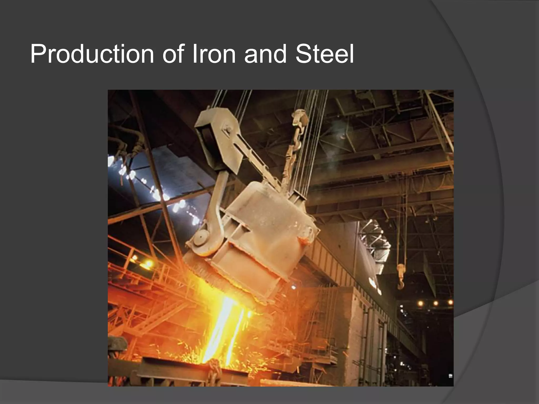
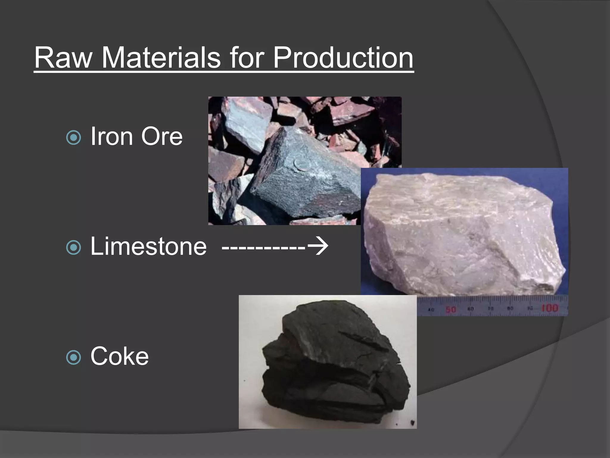
SlideShare a Scribd company logo
Production of Iron and Steel
Raw Materials for Production
 Iron Ore
 Limestone ----------
 Coke
Iron Ore
 Abundant, makes up 5% of earth’s crust
 Is not found in ‘free state’, must be found in rocks
and oxides, hence Iron ore.
 After mining, the ore is crushed and the iron is
separated, then made into pellets, balls or
briquettes using binders, such as water.
 The pellets are typically 65% iron, and about 1” in
diameter.
Coke
 Coke is formed by heating coal to 2100*F (1150 C),
then cooling it in quenching towers.
You need more than Iron? Why coke is
used…
1. Generates high heat, needed in order for chemical
reactions in ironmaking to take place.
2. Produces CO (carbon monoxide) which reduces
iron-oxide to Iron.
Limestone
 Limestone (calcium carbonate) is used to remove
impurities.
 When the metal is melted, limestone combines
with impurities and floats to the top of the metal,
forming slag. The slag can then be removed,
purifying the iron.
Ironmaking
 Coking Coal and iron ore are the basic raw materials
for the production of pig iron, which will further be
refined to steel in the steel works.
 In the coke oven plant coal is processed to coke. Coke
is essential in the lower part of the blast furnace to
maintain the gas permeability. Due to the high weight
load of the burden column simple coal would break into
small particles and block the gas stream.
 As a byproduct of the coking process coke oven gas
mainly consisting of hydrogen and methane is
generated, which is used mainly for generation of
electric power in a thermal power plant.
 Most of the iron ores and additves are traded as
fines and need some pretreatment before being
processed in the blast furnace.
 This preprocess is called sintering, where, by
means of heat
 (approx. 1300°C) the fines are somehow baked to
particles of between 20 and 50 mm mean diameter.
These particles, called sinter, are also permeable
for the reduction gases.
 In the blast furnace the reduction of the iron
ores (Fe2O3) to metallic iron and the melting
of the iron and by products take place.
 Both, reduction and melting need high
temperature, which is generated by
combustion of coke using hot blast, blown in
via tuyeres located around the furnace.
 The reduction gas leaving the furnace is
called top gas and after a cleaning process
used to preheat the air in the hot blast
stoves.
 Hot metal and slag are further tapped
from the hearth of the blast furnace, by
drilling a so called tap hole, which will be
closed after aproximately one to one and a
half hours again.
 The separation of hot metal and slag takes
place in a so called pool runner outside the
furnace, using the density difference.
What is HBI?
 Product of a Direct Reduction process
that has been briquetted at a
temperature of greater than 650 C (1200
F) to a minimum density of 5.0g/cc
 Weight each from 0.5 to 1.5 kg, 1 to 3 ½
lb
 Size
 L=90 to 130 mm, 3 ½ to 5 in
 W=80 to 100 mm, 3 to 4 in
 T=20 to 50 mm, ¾ to 1 ½ in
Definitions
 DR: Direct Reduction. Reduce iron oxide
to metallic iron without melting.
Unreduced ore compounds remain as
undesirable oxides
 DRI: Direct Reduced Iron. Iron oxide
feedstock exits in same form as entered
(pellets in, pellets out; lumps in, lumps
out)
 HBI: Hot Briquetted Iron: DRI that has been
hot (1200 F, 650 C) briquetted to a high
density pillow shaped briquette
 Hot Metal: Molten iron in liquid form, above
2500 F, 1370 C
 Pig Iron: Solid product of the iron blast
furnace
 Residuals: Undesirable elements such as
copper, nickel, chromium, tin, sulfur
molybdenum, phosphorous
 Gangue: Rock minerals in the iron ore such
as silica (SiO2), alumina (Al2O3), calcia
(CaO), magnesia (MgO).
 These remain in the oxide form in DR
processes
 Reduction:
◦ Fe2O3 + 3CO = 2 Fe + 3CO2
◦ 2Fe2O3 + 3H2 = 2Fe + 3H2O
◦ (Fe2O3 > Fe3O4 > FeO > Fe )
Iron Ore (DR Pellet)
Chemistry
Fe 67.00 SiO2 1.60
Al2O3 0.45 CaO 0.60
MgO 0.45 Mn 0.04
P 0.030 S 0.003
Cu 0.003 Pb 0.02
Zn 0.008 V 0.005
HBI Chemistry (Typical)
Total Iron (Fe) 90.00 to 93.00
Acid Gangue 1.95 to 5.10
P 0.015 to 0.060
S 0.005 to 0.020
C 1.07 to 1.60
Stock House
Hot Blast Stoves
Gas Cleaning
Scrubber
Ironmaking in the Blast Furnace Plant
Bell Less Top
Blower
Combustion Air Slag, Hot Metal
Gasholder
Enrichment Gas
Combustion Gas
Sinter Coke
Raw Materials  Pig Iron
 The three raw materials are dumped into a blast
furnace.
 Hot air (2000*F) is blasted into the furnace, which
helps drive the chemical reaction.
 The coke forms CO and the CO reduces the iron
oxide to iron.
 The slag floats to the top and the metal is
transferred to molds and cools. IT IS NOW PIG
IRON, ready for more iron work or steelmaking.
Blast
Furnace
Tuyeres
(Same height as a 10 story building)
Blast
Furnace
•The purpose of a blast furnace
is to reduce and convert iron
oxides into liquid iron called "hot
metal".
•The blast furnace is a huge,
steel stack lined with refractory
brick.
•Iron ore, coke and limestone
are put into the top, and
preheated air is blown into the
bottom.
Why does Iron have to be extracted in a Blast Furnace?
• Iron can be
extracted by the
blast furnace
because it can be
displaced by carbon.
• This is more efficient
method than
electrolysis because
it is more cost
effective
Several reactions take place before the iron is finally produced...
• Oxygen in the air reacts with coke to give carbon
dioxide:
 C(s) + O 2(g)  CO2(g)
• The limestone breaks down to form carbon dioxide:
 CaCO3(s)  CO2 (g) + CaO(s)
• Carbon dioxide produced in 1 + 2 react with more
coke to produce carbon monoxide:
 CO2(g) + C(s)  2CO(g)
• The carbon monoxide reduces the iron in
the ore to give molten iron:
 3CO(g) + Fe2O3(s)  2Fe(l) + 3CO2(g)
• The limestone from 2, reacts with the sand
to form slag (calcium silicate):
 CaO(s) + SiO(s)  CaSiO3(l)
• Both the slag and iron are drained from the
bottom of the furnace.
• The slag is mainly used to build roads.
• The iron whilst molten is poured into moulds
and left to solidify - this is called cast iron and is
used to make railings and storage tanks.
• The rest of the iron is used to make steel.
Steelmaking
 Steelmaking is the second step in producing
steel from iron ore.
 In this stage, impurities such as S, P and
excess carbon are removed from the raw
iron, and alloying elements such as Mn, Ni,
Cr and vanadium are added to produce the
exact steel required.
Steel making processes
 Bessemer Converter Process.
 Open Hearth Process.
 Basic Oxygen Converter Processes.
(1) Bath Agitation Process.
(2) LDAC/OLP Process.
(3) KALDO Process.
 Electric Arc Furnaces.
(1) AOD process.
 Secondary Steel Making.
(1) Vacuum Degassing process (VOD).
(2) Refining by re-melting.
- Electroslag Remelting (ESR).
(3) Ladle Metallurgy.
- Process Capabilities of Ladle Furnace.
Steel making flow chart
Products
Bessemer Process
•In the Bessemer process
compressed air or oxygen is blown
into the bottom of a converter, a
furnace shaped like a cement
mixer, containing molten pig iron.
• The excess carbon in the iron
burns out, other impurities form a
slag, and the furnace is emptied
by tilting. The proportion of scrap
consumption is upto 8%.
Cont….
 In this process molten pig iron is held in a vessel
with perforated bottom called a converter.
 Cold air or oxygen enriched blast is forced through
the metal. This is a autogeneous process, i.e., no
external heat is needed, it is the exothermic chemical
reaction.
Cont….
 Refining is complete in about 15-20 minutes taking
into account the time required for charging, tapping,
teeming, etc.. A tap to tap time of about 30-35
minutes are required.
 It was capable of removing only silicon, carbon,
phosphorous (less than 0.05%) and manganese as
impurities from pig iron, i.e., it was an acid process.
 The large amount of phosphorous (more than 0.05%)
was eliminated by basic process.
Open Hearth Process.
 It is heated by either liquid or liquid and
gaseous fuels using the heat generation
principle so as to attain steel making
temperatures of about 1700ºC.
 A tap-to-tap time of about 6-10 hours.
 It takes much longer time for refining than
bessemer does and hence the heat losses by
radiation.
 The proportion of scrap consumption is 75%.
Basic Oxygen Converter Processes.
(LD, Lintz and Donawitz, Converter)
Basic oxygen furnace showing
BOF vessel during processing of a
heat. The proportion of scrap
consumption is upto 25 %.
Basic-Oxygen
Furnace(BOF)
Oxygen Blowing
Hot Metal Charge
Tap-Out & Transfer
to Ladle Metallurgy
Facility
Scrap Charge
BOF sequence : (1) charging of scrap and (2) pig iron, (3) blowing, (4)
tapping the molten steel, & pouring off the slag.
 The basic oxygen furnace converts iron from the blast
furnace into steel at 1260 to 1300ºC. This is achieved
by blowing oxygen through the molten iron in the
BOF vessel, where it combines with and removes
carbon as carbon monoxide and carbon dioxide.
Unwanted silicon, phosphorus and other elements are
also driven off, while added fluxes (typically lime)
combine with other impurities to be removed as slag.
 Alternative names for this plant/process are steel
converter, BOS (basic oxygen steelmaking), basic
oxygen process (BOP), and LD process.
 BOFs, which can refine a heat (batch) of steel in less than 45
minutes, the latter required five to six hours to process the
metal. The BOF’s rapid operation, lower cost, and ease of
control give it a distinct advantage over previous methods.
 Scrap is dumped into the furnace vessel, followed by the hot
metal from the blast furnace. A lance is lowered from above,
through which blows a high-pressure stream of oxygen to
cause chemical reactions that separate impurities as fumes or
slag. Once refined, the liquid steel and slag are poured into
separate containers.
 However this method involves a risk of increasing the
inclusions and nitrogen contents in the steel due to the oxygen
jet is supersonic and has a speed between 1.5 and 2.2 times the
speed of sound.
 40-50% sulphur is removed and 90% phosphorous is removed.
BATH AGITATION PROCESS
(combined blowing)
 In this process additional gas is introduced through
tuyeres judiciously located in the bottom and (oxygen +
lime) from the top of the converter.
 Better mixing of slag and metal, preventing excessive
compositions.
 Smoother and more predictable carbon-removal and
refining process.
 For production of low carbon steel.
LDAC/OLP PROCESS
 The modified process is known as LDAC process. The
phosphorous is removed from the total system.
 In this process where lime powder is introduced along
with oxygen through the lance to refine high
phosphorous.
 After pouring the high phosphorous (1.8%) pig iron into
the converter, two slag operations are necessary if the
initial phosphorous content in the hot metal is high.
KALDO PROCESS
 In this process high phosphorous iron containing about
1.8% P may be refined with thermal efficiency.
 In blowing position, the furnace is inclined at an angle
of 15 degree.
 The oxygen is blown into the furnace above the bath
surface to refine high phosphorous iron (1.8%) to steel
with low S, P and N.
Electric Furnace
 Steel-making furnace
where scrap is generally
100% of the charge.
 Heat is supplied from
electricity that arcs from
the graphite electrodes to
the metal bath.
 The EAF is a refractory-lined vessel with a retractable
cover through which large graphite electrodes are
lowered once the scrap has been charged and the
furnace top closed. EAFs are usually of 60-150t
capacity per melt, but occasionally larger. However,
they are usually much smaller than BOFs.
 Melting occurs due to the energy released by
arcing between electrode and scrap. There are
normally three electrodes, but only one with
direct current furnaces.
 Much effort has been directed at minimising the
time from scrap charging to steel pouring (tap-to-
tap time). It is now standard practice to transfer
steel to a separate furnace for alloying
modifications (secondary metallurgy) to free-up
the EAF for the next charge. Scrap pre-heating
and oxygen injection also raise productivity and
reduce energy use.
Furnace operation
 The electric arc furnace operates as a
batch melting process producing
batches of molten steel known
"heats". The electric arc furnace
operating cycle is called the tap-to-tap
cycle and is made up of the following
operations:
 Furnace charging.
 Melting.
 Refining.
 De-slagging.
 Tapping.
 Furnace turn-around.
AOD
 AOD stands for argon oxygen decarburization, A process
for further refinement of stainless steel through reduction
of carbon content.
 Most stainless steel is initially produced in an electric arc
furnace before being transferred to a separate ladle
furnace for refining to achieve the precise metallurgical
content required – a process known as secondary
metallurgy or secondary refining.
 The amount of carbon in stainless steel must be lower
than that in carbon steel or lower alloy steel. While
electric arc furnaces (EAF) are the conventional means of
melting and refining stainless steel.
 Molten, unrefined steel is transferred from the
EAF into a separate vessel. A mixture of argon
and oxygen is blown from the bottom of the
vessel through the melted steel.
 Cleaning agents are added to the vessel along
with these gases to eliminate impurities, while
the oxygen combines with carbon in the
unrefined steel to reduce the carbon level. The
presence of argon enhances the affinity of
carbon for oxygen and thus facilitates the
removal of carbon.
SECONDARY STEEL
 Forging grade ingots for critical applications now
requires a close control over the alloy composition,
inclusion and gas content.
 The carbon content in some new grades of flat
products have been brought down to levels which
cannot be economically achieved in primary steel
making processes like EAF or BOF.
 All these developments have spurred the growth of a
whole range of steel refining process. These processes
are called secondary steel making processes, where
the final process of refining, degassing, alloying and
temperature adjustment are carried out in suitably-
equipped vessels between tapping and teeming.
 Modern steel making is therefore carried out in two
stages- the first stage uses primary steel making in
BOF and EAF for the production of a raw steel, which
is then further refined in the second stage by various
process. Key operations can include deoxidation,
desulphurisation and dephosphorisation.
VACUUM DEGASSING PROCESS
 Vacuum degassing (VD) is used following steel
making to reduce the carbon, nitrogen,
hydrogen and sulphur content of molten steel.
Phosphorus can also be reduced.
 The process takes place under vacuum in a ladle
furnace where it is heated and stirred by an
electrical current while oxygen enters from the
top of the vessel , and is frequently employed
by both volume and special steels producers.
 When dealing with high-chromium steels, VD
allows very low carbon content to be achieved
without heavy chromium losses from the melt.
 Vacuum degassing has become widespread as
demand for higher quality steels has grown in
sectors like automotive, construction, offshore,
pipe making and rails.
 In alloy steel products like bearings VD steels
improve fatigue life, while in flat products, very
low carbon VD steels are well suited to
demanding processing and fabrication.
ELECTRO-SLAG RE-MELTING
 The consumable electrode is dipped into a
pool of slag in a water cooled mold.
 An electric current passes through the
slag, between the electrode and the ingot
being formed and superheats the slag so
that drops of metal are melted from the
electrode.
 They travel through the slag to the bottom
of the water cooled mold where they
solidify.
 The slag pool is carried upward as the
ingot forms. The new ingot of refined
material builds up slowly from the bottom
of the mold.
Casting Ingots
Ingots
 While steel is still molten, it is poured into a mold. The
mold may be a square, rectangle or round. The metal
becomes an “ingot” in the mold.
 They can weigh 100 lbs to 40 tons.
 The ingot will be removed from the mold and heated
uniformly to be rolled or formed into a final product.
 HOWEVER – While the molten metal cools, or
solidifies, gasses evolve and can affect the quality of
the steel. This leads to three types of steel: Killed
Steel, Semi-Killed Steel, and Rimmed Steel.
Killed – Semi-Killed – Rimmed Steel
 Killed Steel – This is a fully deoxidized steel, and thus,
has no porosity.
 This is accomplished by using elements like
aluminum to de-oxidize the metal. The impurities
rise and mix with the slag.
 It is called killed because when the metal is poured it
has no bubbles, it is quiet.
 Because it is so solid, not porous, the ingot shrinks
considerably when it cools, and a “pipe” or
“shrinkage cavity” forms. This must be cut off and
scrapped.
Killed – Semi-Killed – Rimmed Steel
 Semi-Killed Steel: This is practically the same as killed
steel, with some minor differences.

 It is only partially de-oxidized, and therefore, is a
little more porous than killed steel.
 Semi-Killed does not shrink as much as it cools, so
the pipe is much smaller and scrap is reduced.
 It is much more economical and efficient to produce.
Killed – Semi-Killed – Rimmed Steel
 Rimmed Steel:
 This is produced by adding elements like aluminum to
the molten metal to remove unwanted gases. The
gasses then form blowholes around the rim.
 Results in little or no piping.
 HOWEVER, impurities also tend to collect in the
center of the ingot, so products or rimmed steel need
to be inspected and tested.
Continuous Casting
-Molten metal skips ingot step,
and goes directly the furnace to
a “tundish”
-Metal solidifies in the mold
-The metal descends @ about
1”/sec
-The solidified metal then goes
through
‘pinch rollers’ that determine the
final
form.
Benefits of Continuous Casting
 Costs less to produce final product
 Metal has more uniform composition and properties
than ingot processing.

More Related Content

What's hot

Iron making
Iron makingIron making
Iron makingguddu_92
 
Non - Ferrous Extraction of Metals Lecture Notes
Non - Ferrous Extraction of Metals Lecture NotesNon - Ferrous Extraction of Metals Lecture Notes
Non - Ferrous Extraction of Metals Lecture Notes
FellowBuddy.com
 
Steel making process
Steel making processSteel making process
Steel making process
Taimoor Hassan
 
Steel making process
Steel making processSteel making process
Steel making process
Maria Beraza Arrieta
 
Electrric arc furnace
Electrric arc furnaceElectrric arc furnace
Electrric arc furnace
Kerri Zhang
 
Steel manufacturing process
Steel manufacturing processSteel manufacturing process
Steel manufacturing process
Ashvani Shukla
 
Introduction to steel making processes
Introduction to steel making processesIntroduction to steel making processes
Introduction to steel making processes
pooja verma
 
Steel manufacturing
Steel manufacturingSteel manufacturing
BASIC OXYGEN STEELMAKING (BOS) - The Processing Route (blast furnace - basic ...
BASIC OXYGEN STEELMAKING (BOS) - The Processing Route (blast furnace - basic ...BASIC OXYGEN STEELMAKING (BOS) - The Processing Route (blast furnace - basic ...
BASIC OXYGEN STEELMAKING (BOS) - The Processing Route (blast furnace - basic ...
Matteo Sporchia
 
blast furnace, done by ahan m r , delhi public school bangalore
  blast furnace, done by ahan m r , delhi public school bangalore  blast furnace, done by ahan m r , delhi public school bangalore
blast furnace, done by ahan m r , delhi public school bangaloreAhan M R
 
Steel melting shop
Steel melting shop Steel melting shop
Steel melting shop
Mukuldev Khunte
 
VACUUM DE-GASING OF METALS
VACUUM DE-GASING OF METALSVACUUM DE-GASING OF METALS
VACUUM DE-GASING OF METALSarif ali
 
Corex Iron Reduction Process
Corex Iron Reduction ProcessCorex Iron Reduction Process
Corex Iron Reduction Process
Harmfree Muchada
 
Refractories and Operation of RH and RH-OB Process
Refractories and Operation of RH and RH-OB ProcessRefractories and Operation of RH and RH-OB Process
Refractories and Operation of RH and RH-OB Process
sampad mishra
 

What's hot (20)

Steel Making Continuous casting I
Steel Making Continuous casting ISteel Making Continuous casting I
Steel Making Continuous casting I
 
Iron making
Iron makingIron making
Iron making
 
Non - Ferrous Extraction of Metals Lecture Notes
Non - Ferrous Extraction of Metals Lecture NotesNon - Ferrous Extraction of Metals Lecture Notes
Non - Ferrous Extraction of Metals Lecture Notes
 
Steel making process
Steel making processSteel making process
Steel making process
 
Steel making process
Steel making processSteel making process
Steel making process
 
Steel Making: Lecture open hearth furnace
Steel Making: Lecture open hearth furnaceSteel Making: Lecture open hearth furnace
Steel Making: Lecture open hearth furnace
 
Steel Making: Lecture Secondary Steel Making
Steel Making: Lecture Secondary Steel Making Steel Making: Lecture Secondary Steel Making
Steel Making: Lecture Secondary Steel Making
 
Electrric arc furnace
Electrric arc furnaceElectrric arc furnace
Electrric arc furnace
 
Steel manufacturing process
Steel manufacturing processSteel manufacturing process
Steel manufacturing process
 
Introduction to steel making processes
Introduction to steel making processesIntroduction to steel making processes
Introduction to steel making processes
 
Steel manufacturing
Steel manufacturingSteel manufacturing
Steel manufacturing
 
BASIC OXYGEN STEELMAKING (BOS) - The Processing Route (blast furnace - basic ...
BASIC OXYGEN STEELMAKING (BOS) - The Processing Route (blast furnace - basic ...BASIC OXYGEN STEELMAKING (BOS) - The Processing Route (blast furnace - basic ...
BASIC OXYGEN STEELMAKING (BOS) - The Processing Route (blast furnace - basic ...
 
blast furnace, done by ahan m r , delhi public school bangalore
  blast furnace, done by ahan m r , delhi public school bangalore  blast furnace, done by ahan m r , delhi public school bangalore
blast furnace, done by ahan m r , delhi public school bangalore
 
Bos
BosBos
Bos
 
Steel melting shop
Steel melting shop Steel melting shop
Steel melting shop
 
Lec Smelting Of Iron
Lec  Smelting Of IronLec  Smelting Of Iron
Lec Smelting Of Iron
 
VACUUM DE-GASING OF METALS
VACUUM DE-GASING OF METALSVACUUM DE-GASING OF METALS
VACUUM DE-GASING OF METALS
 
Corex Iron Reduction Process
Corex Iron Reduction ProcessCorex Iron Reduction Process
Corex Iron Reduction Process
 
Refractories and Operation of RH and RH-OB Process
Refractories and Operation of RH and RH-OB ProcessRefractories and Operation of RH and RH-OB Process
Refractories and Operation of RH and RH-OB Process
 
Steel Making: Ingot casting
Steel Making: Ingot casting Steel Making: Ingot casting
Steel Making: Ingot casting
 

Similar to Ppt_on_steel_making.ppt

02 metals
02 metals02 metals
02 metals
temoor abbasa
 
Chapter2 150109004021-conversion-gate02
Chapter2 150109004021-conversion-gate02Chapter2 150109004021-conversion-gate02
Chapter2 150109004021-conversion-gate02
Cleophas Rwemera
 
Chapter 2: Ferrous Material
Chapter 2: Ferrous MaterialChapter 2: Ferrous Material
Chapter 2: Ferrous Material
syar 2604
 
Iron and steel making. lec.1
Iron and steel making. lec.1Iron and steel making. lec.1
Iron and steel making. lec.1
Ali Hameed
 
Manufacturing of steel
Manufacturing of steelManufacturing of steel
Manufacturing of steel
Cholan PK
 
Chapter 2 ferrous material structure and binary alloy system
Chapter 2   ferrous material structure and binary alloy systemChapter 2   ferrous material structure and binary alloy system
Chapter 2 ferrous material structure and binary alloy systemsakura rena
 
Mat ii chapter 2.1
Mat ii chapter 2.1Mat ii chapter 2.1
Mat ii chapter 2.1
AsegidTadesse2
 
coke and metallurgical coal
coke and metallurgical coalcoke and metallurgical coal
coke and metallurgical coal
knowledge1995
 
Final blast furnace!!! ahan m r digital signed!
Final  blast furnace!!! ahan m r digital signed!Final  blast furnace!!! ahan m r digital signed!
Final blast furnace!!! ahan m r digital signed!Ahan M R
 
Material Technology
Material TechnologyMaterial Technology
Material Technology
Malaysia
 
OVERVIEW OF STEEL PLANT AND STEEL MANUFACTURING
OVERVIEW OF STEEL PLANT AND STEEL MANUFACTURINGOVERVIEW OF STEEL PLANT AND STEEL MANUFACTURING
OVERVIEW OF STEEL PLANT AND STEEL MANUFACTURING
Abhishek Saha
 
extraction of Fe and Cu metals from their ores , alloys
extraction of Fe and Cu metals from their ores , alloysextraction of Fe and Cu metals from their ores , alloys
extraction of Fe and Cu metals from their ores , alloys
AnujaKamthe1
 
Chapter2 (JF302)
Chapter2 (JF302)Chapter2 (JF302)
Chapter2 (JF302)
Mohd Nurilhadi Darmi
 
Steel plant ppt 1
Steel plant ppt 1Steel plant ppt 1
Steel plant ppt 1
venuprathimala
 
Steel making process assignment
Steel making process assignmentSteel making process assignment
Steel making process assignment
KeoSokheng
 
Manufacturing of Steel
Manufacturing of Steel Manufacturing of Steel
Manufacturing of Steel
Muhammad Ahmed
 

Similar to Ppt_on_steel_making.ppt (20)

02 metals
02 metals02 metals
02 metals
 
Chapter2 150109004021-conversion-gate02
Chapter2 150109004021-conversion-gate02Chapter2 150109004021-conversion-gate02
Chapter2 150109004021-conversion-gate02
 
Chapter 2: Ferrous Material
Chapter 2: Ferrous MaterialChapter 2: Ferrous Material
Chapter 2: Ferrous Material
 
Iron and steel making. lec.1
Iron and steel making. lec.1Iron and steel making. lec.1
Iron and steel making. lec.1
 
Manufacturing of steel
Manufacturing of steelManufacturing of steel
Manufacturing of steel
 
Chapter 2 ferrous material structure and binary alloy system
Chapter 2   ferrous material structure and binary alloy systemChapter 2   ferrous material structure and binary alloy system
Chapter 2 ferrous material structure and binary alloy system
 
Mat ii chapter 2.1
Mat ii chapter 2.1Mat ii chapter 2.1
Mat ii chapter 2.1
 
coke and metallurgical coal
coke and metallurgical coalcoke and metallurgical coal
coke and metallurgical coal
 
Manu
ManuManu
Manu
 
Final blast furnace!!! ahan m r digital signed!
Final  blast furnace!!! ahan m r digital signed!Final  blast furnace!!! ahan m r digital signed!
Final blast furnace!!! ahan m r digital signed!
 
Material Technology
Material TechnologyMaterial Technology
Material Technology
 
OVERVIEW OF STEEL PLANT AND STEEL MANUFACTURING
OVERVIEW OF STEEL PLANT AND STEEL MANUFACTURINGOVERVIEW OF STEEL PLANT AND STEEL MANUFACTURING
OVERVIEW OF STEEL PLANT AND STEEL MANUFACTURING
 
extraction of Fe and Cu metals from their ores , alloys
extraction of Fe and Cu metals from their ores , alloysextraction of Fe and Cu metals from their ores , alloys
extraction of Fe and Cu metals from their ores , alloys
 
Chapter2 (JF302)
Chapter2 (JF302)Chapter2 (JF302)
Chapter2 (JF302)
 
Slide
SlideSlide
Slide
 
Chapter 2
Chapter 2Chapter 2
Chapter 2
 
Ms chapter 3
Ms chapter 3Ms chapter 3
Ms chapter 3
 
Steel plant ppt 1
Steel plant ppt 1Steel plant ppt 1
Steel plant ppt 1
 
Steel making process assignment
Steel making process assignmentSteel making process assignment
Steel making process assignment
 
Manufacturing of Steel
Manufacturing of Steel Manufacturing of Steel
Manufacturing of Steel
 

Recently uploaded

power quality voltage fluctuation UNIT - I.pptx
power quality voltage fluctuation UNIT - I.pptxpower quality voltage fluctuation UNIT - I.pptx
power quality voltage fluctuation UNIT - I.pptx
ViniHema
 
Student information management system project report ii.pdf
Student information management system project report ii.pdfStudent information management system project report ii.pdf
Student information management system project report ii.pdf
Kamal Acharya
 
Nuclear Power Economics and Structuring 2024
Nuclear Power Economics and Structuring 2024Nuclear Power Economics and Structuring 2024
Nuclear Power Economics and Structuring 2024
Massimo Talia
 
J.Yang, ICLR 2024, MLILAB, KAIST AI.pdf
J.Yang,  ICLR 2024, MLILAB, KAIST AI.pdfJ.Yang,  ICLR 2024, MLILAB, KAIST AI.pdf
J.Yang, ICLR 2024, MLILAB, KAIST AI.pdf
MLILAB
 
Industrial Training at Shahjalal Fertilizer Company Limited (SFCL)
Industrial Training at Shahjalal Fertilizer Company Limited (SFCL)Industrial Training at Shahjalal Fertilizer Company Limited (SFCL)
Industrial Training at Shahjalal Fertilizer Company Limited (SFCL)
MdTanvirMahtab2
 
block diagram and signal flow graph representation
block diagram and signal flow graph representationblock diagram and signal flow graph representation
block diagram and signal flow graph representation
Divya Somashekar
 
Democratizing Fuzzing at Scale by Abhishek Arya
Democratizing Fuzzing at Scale by Abhishek AryaDemocratizing Fuzzing at Scale by Abhishek Arya
Democratizing Fuzzing at Scale by Abhishek Arya
abh.arya
 
addressing modes in computer architecture
addressing modes  in computer architectureaddressing modes  in computer architecture
addressing modes in computer architecture
ShahidSultan24
 
Water Industry Process Automation and Control Monthly - May 2024.pdf
Water Industry Process Automation and Control Monthly - May 2024.pdfWater Industry Process Automation and Control Monthly - May 2024.pdf
Water Industry Process Automation and Control Monthly - May 2024.pdf
Water Industry Process Automation & Control
 
ethical hacking-mobile hacking methods.ppt
ethical hacking-mobile hacking methods.pptethical hacking-mobile hacking methods.ppt
ethical hacking-mobile hacking methods.ppt
Jayaprasanna4
 
Standard Reomte Control Interface - Neometrix
Standard Reomte Control Interface - NeometrixStandard Reomte Control Interface - Neometrix
Standard Reomte Control Interface - Neometrix
Neometrix_Engineering_Pvt_Ltd
 
COLLEGE BUS MANAGEMENT SYSTEM PROJECT REPORT.pdf
COLLEGE BUS MANAGEMENT SYSTEM PROJECT REPORT.pdfCOLLEGE BUS MANAGEMENT SYSTEM PROJECT REPORT.pdf
COLLEGE BUS MANAGEMENT SYSTEM PROJECT REPORT.pdf
Kamal Acharya
 
DESIGN A COTTON SEED SEPARATION MACHINE.docx
DESIGN A COTTON SEED SEPARATION MACHINE.docxDESIGN A COTTON SEED SEPARATION MACHINE.docx
DESIGN A COTTON SEED SEPARATION MACHINE.docx
FluxPrime1
 
The Benefits and Techniques of Trenchless Pipe Repair.pdf
The Benefits and Techniques of Trenchless Pipe Repair.pdfThe Benefits and Techniques of Trenchless Pipe Repair.pdf
The Benefits and Techniques of Trenchless Pipe Repair.pdf
Pipe Restoration Solutions
 
WATER CRISIS and its solutions-pptx 1234
WATER CRISIS and its solutions-pptx 1234WATER CRISIS and its solutions-pptx 1234
WATER CRISIS and its solutions-pptx 1234
AafreenAbuthahir2
 
CME397 Surface Engineering- Professional Elective
CME397 Surface Engineering- Professional ElectiveCME397 Surface Engineering- Professional Elective
CME397 Surface Engineering- Professional Elective
karthi keyan
 
Courier management system project report.pdf
Courier management system project report.pdfCourier management system project report.pdf
Courier management system project report.pdf
Kamal Acharya
 
road safety engineering r s e unit 3.pdf
road safety engineering  r s e unit 3.pdfroad safety engineering  r s e unit 3.pdf
road safety engineering r s e unit 3.pdf
VENKATESHvenky89705
 
在线办理(ANU毕业证书)澳洲国立大学毕业证录取通知书一模一样
在线办理(ANU毕业证书)澳洲国立大学毕业证录取通知书一模一样在线办理(ANU毕业证书)澳洲国立大学毕业证录取通知书一模一样
在线办理(ANU毕业证书)澳洲国立大学毕业证录取通知书一模一样
obonagu
 
Quality defects in TMT Bars, Possible causes and Potential Solutions.
Quality defects in TMT Bars, Possible causes and Potential Solutions.Quality defects in TMT Bars, Possible causes and Potential Solutions.
Quality defects in TMT Bars, Possible causes and Potential Solutions.
PrashantGoswami42
 

Recently uploaded (20)

power quality voltage fluctuation UNIT - I.pptx
power quality voltage fluctuation UNIT - I.pptxpower quality voltage fluctuation UNIT - I.pptx
power quality voltage fluctuation UNIT - I.pptx
 
Student information management system project report ii.pdf
Student information management system project report ii.pdfStudent information management system project report ii.pdf
Student information management system project report ii.pdf
 
Nuclear Power Economics and Structuring 2024
Nuclear Power Economics and Structuring 2024Nuclear Power Economics and Structuring 2024
Nuclear Power Economics and Structuring 2024
 
J.Yang, ICLR 2024, MLILAB, KAIST AI.pdf
J.Yang,  ICLR 2024, MLILAB, KAIST AI.pdfJ.Yang,  ICLR 2024, MLILAB, KAIST AI.pdf
J.Yang, ICLR 2024, MLILAB, KAIST AI.pdf
 
Industrial Training at Shahjalal Fertilizer Company Limited (SFCL)
Industrial Training at Shahjalal Fertilizer Company Limited (SFCL)Industrial Training at Shahjalal Fertilizer Company Limited (SFCL)
Industrial Training at Shahjalal Fertilizer Company Limited (SFCL)
 
block diagram and signal flow graph representation
block diagram and signal flow graph representationblock diagram and signal flow graph representation
block diagram and signal flow graph representation
 
Democratizing Fuzzing at Scale by Abhishek Arya
Democratizing Fuzzing at Scale by Abhishek AryaDemocratizing Fuzzing at Scale by Abhishek Arya
Democratizing Fuzzing at Scale by Abhishek Arya
 
addressing modes in computer architecture
addressing modes  in computer architectureaddressing modes  in computer architecture
addressing modes in computer architecture
 
Water Industry Process Automation and Control Monthly - May 2024.pdf
Water Industry Process Automation and Control Monthly - May 2024.pdfWater Industry Process Automation and Control Monthly - May 2024.pdf
Water Industry Process Automation and Control Monthly - May 2024.pdf
 
ethical hacking-mobile hacking methods.ppt
ethical hacking-mobile hacking methods.pptethical hacking-mobile hacking methods.ppt
ethical hacking-mobile hacking methods.ppt
 
Standard Reomte Control Interface - Neometrix
Standard Reomte Control Interface - NeometrixStandard Reomte Control Interface - Neometrix
Standard Reomte Control Interface - Neometrix
 
COLLEGE BUS MANAGEMENT SYSTEM PROJECT REPORT.pdf
COLLEGE BUS MANAGEMENT SYSTEM PROJECT REPORT.pdfCOLLEGE BUS MANAGEMENT SYSTEM PROJECT REPORT.pdf
COLLEGE BUS MANAGEMENT SYSTEM PROJECT REPORT.pdf
 
DESIGN A COTTON SEED SEPARATION MACHINE.docx
DESIGN A COTTON SEED SEPARATION MACHINE.docxDESIGN A COTTON SEED SEPARATION MACHINE.docx
DESIGN A COTTON SEED SEPARATION MACHINE.docx
 
The Benefits and Techniques of Trenchless Pipe Repair.pdf
The Benefits and Techniques of Trenchless Pipe Repair.pdfThe Benefits and Techniques of Trenchless Pipe Repair.pdf
The Benefits and Techniques of Trenchless Pipe Repair.pdf
 
WATER CRISIS and its solutions-pptx 1234
WATER CRISIS and its solutions-pptx 1234WATER CRISIS and its solutions-pptx 1234
WATER CRISIS and its solutions-pptx 1234
 
CME397 Surface Engineering- Professional Elective
CME397 Surface Engineering- Professional ElectiveCME397 Surface Engineering- Professional Elective
CME397 Surface Engineering- Professional Elective
 
Courier management system project report.pdf
Courier management system project report.pdfCourier management system project report.pdf
Courier management system project report.pdf
 
road safety engineering r s e unit 3.pdf
road safety engineering  r s e unit 3.pdfroad safety engineering  r s e unit 3.pdf
road safety engineering r s e unit 3.pdf
 
在线办理(ANU毕业证书)澳洲国立大学毕业证录取通知书一模一样
在线办理(ANU毕业证书)澳洲国立大学毕业证录取通知书一模一样在线办理(ANU毕业证书)澳洲国立大学毕业证录取通知书一模一样
在线办理(ANU毕业证书)澳洲国立大学毕业证录取通知书一模一样
 
Quality defects in TMT Bars, Possible causes and Potential Solutions.
Quality defects in TMT Bars, Possible causes and Potential Solutions.Quality defects in TMT Bars, Possible causes and Potential Solutions.
Quality defects in TMT Bars, Possible causes and Potential Solutions.
 

Ppt_on_steel_making.ppt

  • 1. Production of Iron and Steel
  • 2. Raw Materials for Production  Iron Ore  Limestone ----------  Coke
  • 3. Iron Ore  Abundant, makes up 5% of earth’s crust  Is not found in ‘free state’, must be found in rocks and oxides, hence Iron ore.  After mining, the ore is crushed and the iron is separated, then made into pellets, balls or briquettes using binders, such as water.  The pellets are typically 65% iron, and about 1” in diameter.
  • 4. Coke  Coke is formed by heating coal to 2100*F (1150 C), then cooling it in quenching towers. You need more than Iron? Why coke is used… 1. Generates high heat, needed in order for chemical reactions in ironmaking to take place. 2. Produces CO (carbon monoxide) which reduces iron-oxide to Iron.
  • 5. Limestone  Limestone (calcium carbonate) is used to remove impurities.  When the metal is melted, limestone combines with impurities and floats to the top of the metal, forming slag. The slag can then be removed, purifying the iron.
  • 7.  Coking Coal and iron ore are the basic raw materials for the production of pig iron, which will further be refined to steel in the steel works.  In the coke oven plant coal is processed to coke. Coke is essential in the lower part of the blast furnace to maintain the gas permeability. Due to the high weight load of the burden column simple coal would break into small particles and block the gas stream.  As a byproduct of the coking process coke oven gas mainly consisting of hydrogen and methane is generated, which is used mainly for generation of electric power in a thermal power plant.
  • 8.  Most of the iron ores and additves are traded as fines and need some pretreatment before being processed in the blast furnace.  This preprocess is called sintering, where, by means of heat  (approx. 1300°C) the fines are somehow baked to particles of between 20 and 50 mm mean diameter. These particles, called sinter, are also permeable for the reduction gases.
  • 9.  In the blast furnace the reduction of the iron ores (Fe2O3) to metallic iron and the melting of the iron and by products take place.  Both, reduction and melting need high temperature, which is generated by combustion of coke using hot blast, blown in via tuyeres located around the furnace.  The reduction gas leaving the furnace is called top gas and after a cleaning process used to preheat the air in the hot blast stoves.
  • 10.  Hot metal and slag are further tapped from the hearth of the blast furnace, by drilling a so called tap hole, which will be closed after aproximately one to one and a half hours again.  The separation of hot metal and slag takes place in a so called pool runner outside the furnace, using the density difference.
  • 11. What is HBI?  Product of a Direct Reduction process that has been briquetted at a temperature of greater than 650 C (1200 F) to a minimum density of 5.0g/cc  Weight each from 0.5 to 1.5 kg, 1 to 3 ½ lb  Size  L=90 to 130 mm, 3 ½ to 5 in  W=80 to 100 mm, 3 to 4 in  T=20 to 50 mm, ¾ to 1 ½ in
  • 12. Definitions  DR: Direct Reduction. Reduce iron oxide to metallic iron without melting. Unreduced ore compounds remain as undesirable oxides  DRI: Direct Reduced Iron. Iron oxide feedstock exits in same form as entered (pellets in, pellets out; lumps in, lumps out)
  • 13.  HBI: Hot Briquetted Iron: DRI that has been hot (1200 F, 650 C) briquetted to a high density pillow shaped briquette  Hot Metal: Molten iron in liquid form, above 2500 F, 1370 C  Pig Iron: Solid product of the iron blast furnace  Residuals: Undesirable elements such as copper, nickel, chromium, tin, sulfur molybdenum, phosphorous
  • 14.  Gangue: Rock minerals in the iron ore such as silica (SiO2), alumina (Al2O3), calcia (CaO), magnesia (MgO).  These remain in the oxide form in DR processes  Reduction: ◦ Fe2O3 + 3CO = 2 Fe + 3CO2 ◦ 2Fe2O3 + 3H2 = 2Fe + 3H2O ◦ (Fe2O3 > Fe3O4 > FeO > Fe )
  • 15. Iron Ore (DR Pellet) Chemistry Fe 67.00 SiO2 1.60 Al2O3 0.45 CaO 0.60 MgO 0.45 Mn 0.04 P 0.030 S 0.003 Cu 0.003 Pb 0.02 Zn 0.008 V 0.005
  • 16. HBI Chemistry (Typical) Total Iron (Fe) 90.00 to 93.00 Acid Gangue 1.95 to 5.10 P 0.015 to 0.060 S 0.005 to 0.020 C 1.07 to 1.60
  • 17. Stock House Hot Blast Stoves Gas Cleaning Scrubber Ironmaking in the Blast Furnace Plant Bell Less Top Blower Combustion Air Slag, Hot Metal Gasholder Enrichment Gas Combustion Gas Sinter Coke
  • 18. Raw Materials  Pig Iron  The three raw materials are dumped into a blast furnace.  Hot air (2000*F) is blasted into the furnace, which helps drive the chemical reaction.  The coke forms CO and the CO reduces the iron oxide to iron.  The slag floats to the top and the metal is transferred to molds and cools. IT IS NOW PIG IRON, ready for more iron work or steelmaking.
  • 20. Blast Furnace •The purpose of a blast furnace is to reduce and convert iron oxides into liquid iron called "hot metal". •The blast furnace is a huge, steel stack lined with refractory brick. •Iron ore, coke and limestone are put into the top, and preheated air is blown into the bottom.
  • 21. Why does Iron have to be extracted in a Blast Furnace? • Iron can be extracted by the blast furnace because it can be displaced by carbon. • This is more efficient method than electrolysis because it is more cost effective
  • 22. Several reactions take place before the iron is finally produced... • Oxygen in the air reacts with coke to give carbon dioxide:  C(s) + O 2(g)  CO2(g) • The limestone breaks down to form carbon dioxide:  CaCO3(s)  CO2 (g) + CaO(s) • Carbon dioxide produced in 1 + 2 react with more coke to produce carbon monoxide:  CO2(g) + C(s)  2CO(g)
  • 23. • The carbon monoxide reduces the iron in the ore to give molten iron:  3CO(g) + Fe2O3(s)  2Fe(l) + 3CO2(g) • The limestone from 2, reacts with the sand to form slag (calcium silicate):  CaO(s) + SiO(s)  CaSiO3(l)
  • 24. • Both the slag and iron are drained from the bottom of the furnace. • The slag is mainly used to build roads. • The iron whilst molten is poured into moulds and left to solidify - this is called cast iron and is used to make railings and storage tanks. • The rest of the iron is used to make steel.
  • 25. Steelmaking  Steelmaking is the second step in producing steel from iron ore.  In this stage, impurities such as S, P and excess carbon are removed from the raw iron, and alloying elements such as Mn, Ni, Cr and vanadium are added to produce the exact steel required.
  • 26. Steel making processes  Bessemer Converter Process.  Open Hearth Process.  Basic Oxygen Converter Processes. (1) Bath Agitation Process. (2) LDAC/OLP Process. (3) KALDO Process.  Electric Arc Furnaces. (1) AOD process.  Secondary Steel Making. (1) Vacuum Degassing process (VOD). (2) Refining by re-melting. - Electroslag Remelting (ESR). (3) Ladle Metallurgy. - Process Capabilities of Ladle Furnace.
  • 29. Bessemer Process •In the Bessemer process compressed air or oxygen is blown into the bottom of a converter, a furnace shaped like a cement mixer, containing molten pig iron. • The excess carbon in the iron burns out, other impurities form a slag, and the furnace is emptied by tilting. The proportion of scrap consumption is upto 8%.
  • 30. Cont….  In this process molten pig iron is held in a vessel with perforated bottom called a converter.  Cold air or oxygen enriched blast is forced through the metal. This is a autogeneous process, i.e., no external heat is needed, it is the exothermic chemical reaction.
  • 31. Cont….  Refining is complete in about 15-20 minutes taking into account the time required for charging, tapping, teeming, etc.. A tap to tap time of about 30-35 minutes are required.  It was capable of removing only silicon, carbon, phosphorous (less than 0.05%) and manganese as impurities from pig iron, i.e., it was an acid process.  The large amount of phosphorous (more than 0.05%) was eliminated by basic process.
  • 33.  It is heated by either liquid or liquid and gaseous fuels using the heat generation principle so as to attain steel making temperatures of about 1700ºC.  A tap-to-tap time of about 6-10 hours.  It takes much longer time for refining than bessemer does and hence the heat losses by radiation.  The proportion of scrap consumption is 75%.
  • 34. Basic Oxygen Converter Processes. (LD, Lintz and Donawitz, Converter) Basic oxygen furnace showing BOF vessel during processing of a heat. The proportion of scrap consumption is upto 25 %.
  • 35. Basic-Oxygen Furnace(BOF) Oxygen Blowing Hot Metal Charge Tap-Out & Transfer to Ladle Metallurgy Facility Scrap Charge BOF sequence : (1) charging of scrap and (2) pig iron, (3) blowing, (4) tapping the molten steel, & pouring off the slag.
  • 36.  The basic oxygen furnace converts iron from the blast furnace into steel at 1260 to 1300ºC. This is achieved by blowing oxygen through the molten iron in the BOF vessel, where it combines with and removes carbon as carbon monoxide and carbon dioxide. Unwanted silicon, phosphorus and other elements are also driven off, while added fluxes (typically lime) combine with other impurities to be removed as slag.  Alternative names for this plant/process are steel converter, BOS (basic oxygen steelmaking), basic oxygen process (BOP), and LD process.
  • 37.  BOFs, which can refine a heat (batch) of steel in less than 45 minutes, the latter required five to six hours to process the metal. The BOF’s rapid operation, lower cost, and ease of control give it a distinct advantage over previous methods.  Scrap is dumped into the furnace vessel, followed by the hot metal from the blast furnace. A lance is lowered from above, through which blows a high-pressure stream of oxygen to cause chemical reactions that separate impurities as fumes or slag. Once refined, the liquid steel and slag are poured into separate containers.  However this method involves a risk of increasing the inclusions and nitrogen contents in the steel due to the oxygen jet is supersonic and has a speed between 1.5 and 2.2 times the speed of sound.  40-50% sulphur is removed and 90% phosphorous is removed.
  • 38. BATH AGITATION PROCESS (combined blowing)  In this process additional gas is introduced through tuyeres judiciously located in the bottom and (oxygen + lime) from the top of the converter.  Better mixing of slag and metal, preventing excessive compositions.  Smoother and more predictable carbon-removal and refining process.  For production of low carbon steel.
  • 39. LDAC/OLP PROCESS  The modified process is known as LDAC process. The phosphorous is removed from the total system.  In this process where lime powder is introduced along with oxygen through the lance to refine high phosphorous.  After pouring the high phosphorous (1.8%) pig iron into the converter, two slag operations are necessary if the initial phosphorous content in the hot metal is high.
  • 40. KALDO PROCESS  In this process high phosphorous iron containing about 1.8% P may be refined with thermal efficiency.  In blowing position, the furnace is inclined at an angle of 15 degree.  The oxygen is blown into the furnace above the bath surface to refine high phosphorous iron (1.8%) to steel with low S, P and N.
  • 41. Electric Furnace  Steel-making furnace where scrap is generally 100% of the charge.  Heat is supplied from electricity that arcs from the graphite electrodes to the metal bath.
  • 42.  The EAF is a refractory-lined vessel with a retractable cover through which large graphite electrodes are lowered once the scrap has been charged and the furnace top closed. EAFs are usually of 60-150t capacity per melt, but occasionally larger. However, they are usually much smaller than BOFs.
  • 43.  Melting occurs due to the energy released by arcing between electrode and scrap. There are normally three electrodes, but only one with direct current furnaces.  Much effort has been directed at minimising the time from scrap charging to steel pouring (tap-to- tap time). It is now standard practice to transfer steel to a separate furnace for alloying modifications (secondary metallurgy) to free-up the EAF for the next charge. Scrap pre-heating and oxygen injection also raise productivity and reduce energy use.
  • 44. Furnace operation  The electric arc furnace operates as a batch melting process producing batches of molten steel known "heats". The electric arc furnace operating cycle is called the tap-to-tap cycle and is made up of the following operations:  Furnace charging.  Melting.  Refining.  De-slagging.  Tapping.  Furnace turn-around.
  • 45. AOD  AOD stands for argon oxygen decarburization, A process for further refinement of stainless steel through reduction of carbon content.  Most stainless steel is initially produced in an electric arc furnace before being transferred to a separate ladle furnace for refining to achieve the precise metallurgical content required – a process known as secondary metallurgy or secondary refining.  The amount of carbon in stainless steel must be lower than that in carbon steel or lower alloy steel. While electric arc furnaces (EAF) are the conventional means of melting and refining stainless steel.
  • 46.  Molten, unrefined steel is transferred from the EAF into a separate vessel. A mixture of argon and oxygen is blown from the bottom of the vessel through the melted steel.  Cleaning agents are added to the vessel along with these gases to eliminate impurities, while the oxygen combines with carbon in the unrefined steel to reduce the carbon level. The presence of argon enhances the affinity of carbon for oxygen and thus facilitates the removal of carbon.
  • 47. SECONDARY STEEL  Forging grade ingots for critical applications now requires a close control over the alloy composition, inclusion and gas content.  The carbon content in some new grades of flat products have been brought down to levels which cannot be economically achieved in primary steel making processes like EAF or BOF.
  • 48.  All these developments have spurred the growth of a whole range of steel refining process. These processes are called secondary steel making processes, where the final process of refining, degassing, alloying and temperature adjustment are carried out in suitably- equipped vessels between tapping and teeming.  Modern steel making is therefore carried out in two stages- the first stage uses primary steel making in BOF and EAF for the production of a raw steel, which is then further refined in the second stage by various process. Key operations can include deoxidation, desulphurisation and dephosphorisation.
  • 49. VACUUM DEGASSING PROCESS  Vacuum degassing (VD) is used following steel making to reduce the carbon, nitrogen, hydrogen and sulphur content of molten steel. Phosphorus can also be reduced.  The process takes place under vacuum in a ladle furnace where it is heated and stirred by an electrical current while oxygen enters from the top of the vessel , and is frequently employed by both volume and special steels producers.
  • 50.  When dealing with high-chromium steels, VD allows very low carbon content to be achieved without heavy chromium losses from the melt.  Vacuum degassing has become widespread as demand for higher quality steels has grown in sectors like automotive, construction, offshore, pipe making and rails.  In alloy steel products like bearings VD steels improve fatigue life, while in flat products, very low carbon VD steels are well suited to demanding processing and fabrication.
  • 51. ELECTRO-SLAG RE-MELTING  The consumable electrode is dipped into a pool of slag in a water cooled mold.  An electric current passes through the slag, between the electrode and the ingot being formed and superheats the slag so that drops of metal are melted from the electrode.  They travel through the slag to the bottom of the water cooled mold where they solidify.  The slag pool is carried upward as the ingot forms. The new ingot of refined material builds up slowly from the bottom of the mold.
  • 53. Ingots  While steel is still molten, it is poured into a mold. The mold may be a square, rectangle or round. The metal becomes an “ingot” in the mold.  They can weigh 100 lbs to 40 tons.  The ingot will be removed from the mold and heated uniformly to be rolled or formed into a final product.  HOWEVER – While the molten metal cools, or solidifies, gasses evolve and can affect the quality of the steel. This leads to three types of steel: Killed Steel, Semi-Killed Steel, and Rimmed Steel.
  • 54. Killed – Semi-Killed – Rimmed Steel  Killed Steel – This is a fully deoxidized steel, and thus, has no porosity.  This is accomplished by using elements like aluminum to de-oxidize the metal. The impurities rise and mix with the slag.  It is called killed because when the metal is poured it has no bubbles, it is quiet.  Because it is so solid, not porous, the ingot shrinks considerably when it cools, and a “pipe” or “shrinkage cavity” forms. This must be cut off and scrapped.
  • 55. Killed – Semi-Killed – Rimmed Steel  Semi-Killed Steel: This is practically the same as killed steel, with some minor differences.   It is only partially de-oxidized, and therefore, is a little more porous than killed steel.  Semi-Killed does not shrink as much as it cools, so the pipe is much smaller and scrap is reduced.  It is much more economical and efficient to produce.
  • 56. Killed – Semi-Killed – Rimmed Steel  Rimmed Steel:  This is produced by adding elements like aluminum to the molten metal to remove unwanted gases. The gasses then form blowholes around the rim.  Results in little or no piping.  HOWEVER, impurities also tend to collect in the center of the ingot, so products or rimmed steel need to be inspected and tested.
  • 57. Continuous Casting -Molten metal skips ingot step, and goes directly the furnace to a “tundish” -Metal solidifies in the mold -The metal descends @ about 1”/sec -The solidified metal then goes through ‘pinch rollers’ that determine the final form.
  • 58. Benefits of Continuous Casting  Costs less to produce final product  Metal has more uniform composition and properties than ingot processing.