


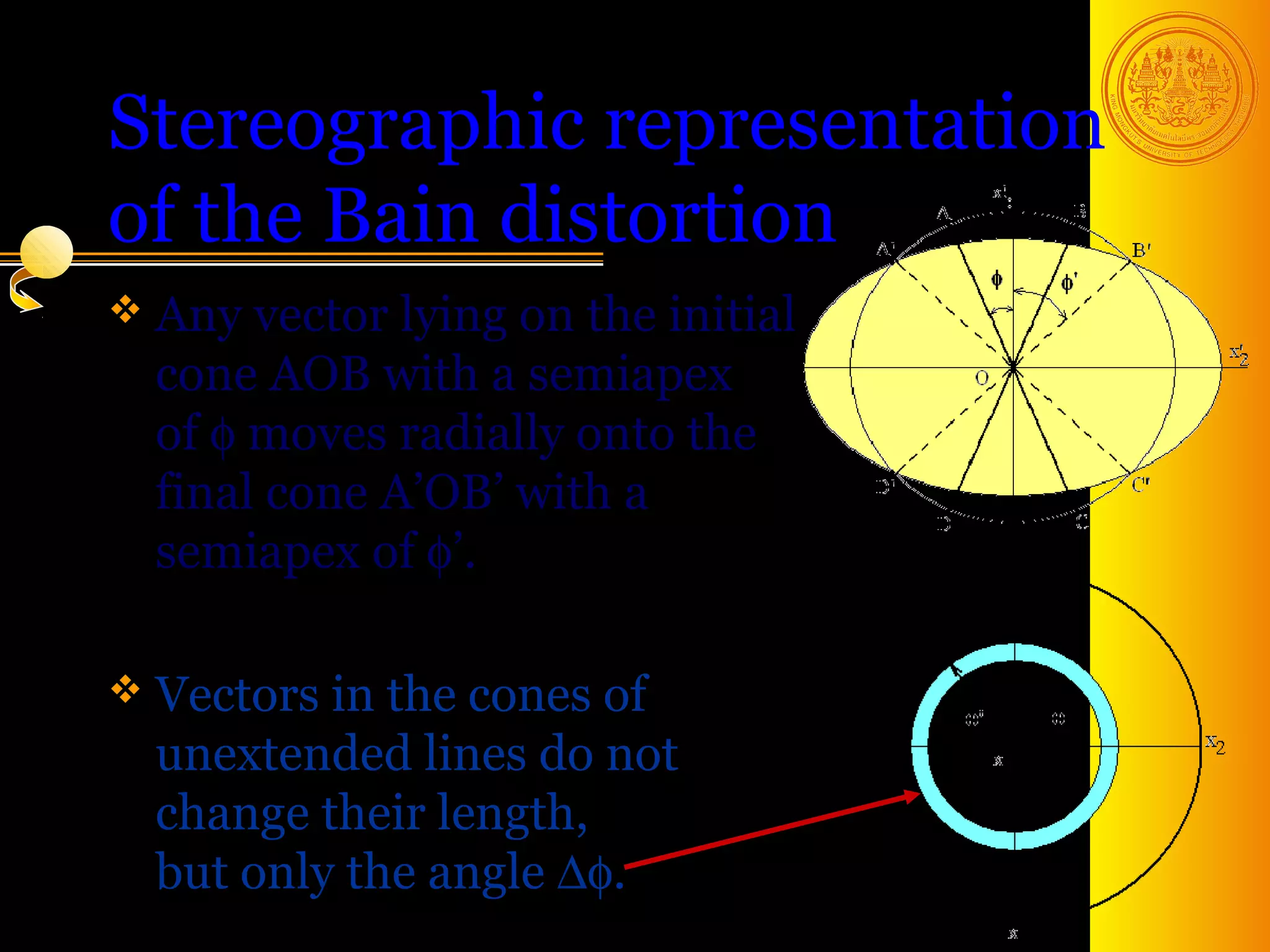

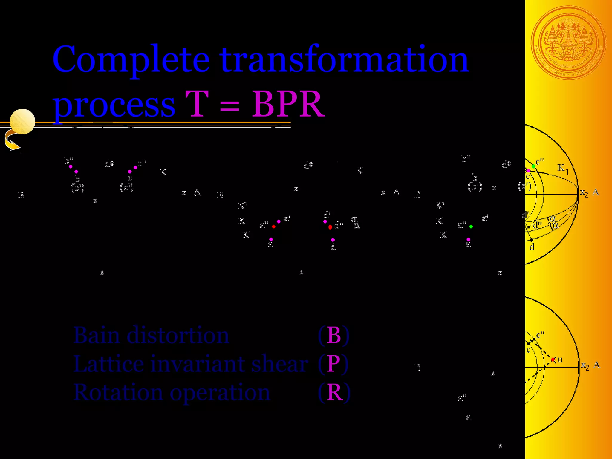
![Bain distortion with twinning
Twinned martensite can take place by having
alternate regions in the parent phase undergo
the lattice deformation along different
contraction axes, which are initially at right
angles to each other.
In the first region, contraction occurs along
the x3 [ 001] f axis.
In the adjacent region, contraction direction
can be either x1 [100] f or x2 [ 010] f axis.
Two rigid body rotations are also involved in
the twinning analysis. 36](https://image.slidesharecdn.com/mt610phasetransformationsinsolidsiv-130211133504-phpapp02/75/Mt-610-phasetransformationsinsolids_iv-36-2048.jpg)
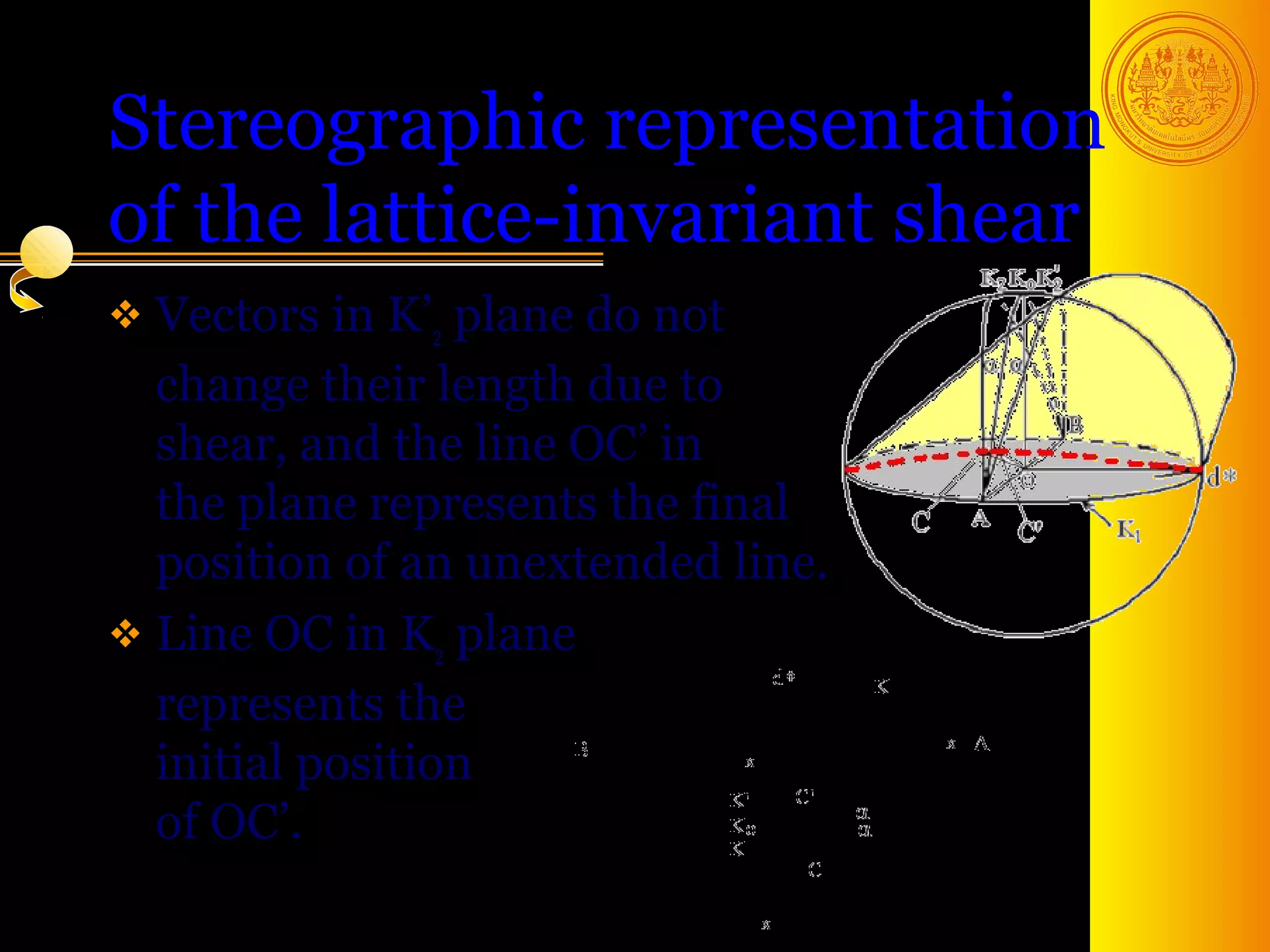
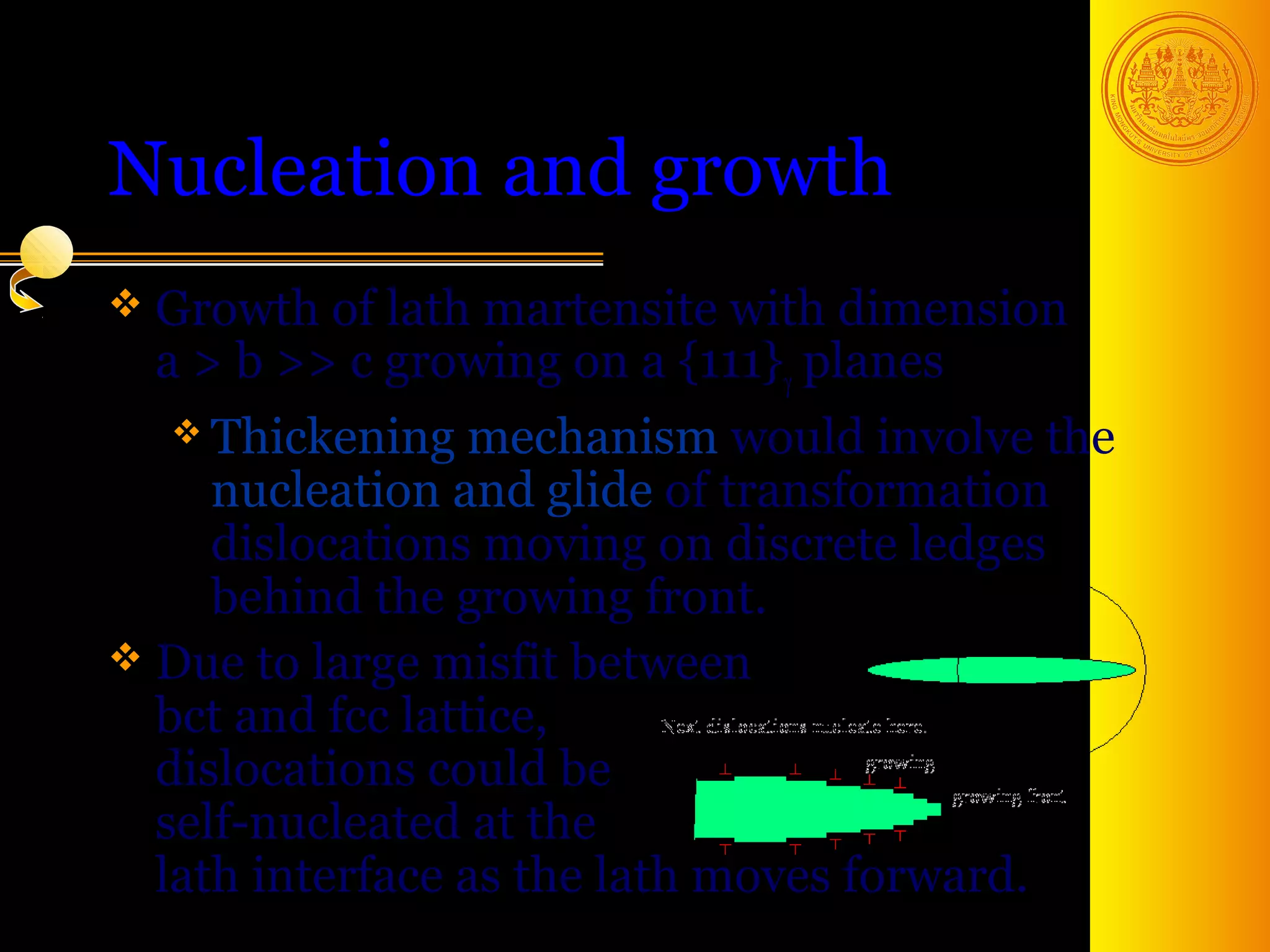
![Nucleation and growth
Dissociation of a dislocation
into 2 partials is favorable
→ lower strain energy.
r r r
To generate b1 = b2 + b3
bcc structure, a a a
[ 110] = [ 211] + 121
the requirements are that all 2 6 6
green atoms move (shear)
a
forward by 12 [ 211] and an
additional dilatation
to correct lattice spacings. 39](https://image.slidesharecdn.com/mt610phasetransformationsinsolidsiv-130211133504-phpapp02/75/Mt-610-phasetransformationsinsolids_iv-39-2048.jpg)


The document discusses phase transformations in solids, focusing on diffusionless martensitic transformations. It describes the mechanisms of martensite formation, including the Bain distortion, lattice-invariant shear, and rigid body rotation that constitute the complete transformation. It discusses nucleation and growth of martensite plates and laths, and how alloying elements and pressure can affect the martensitic transformation.