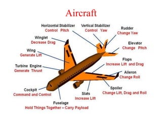
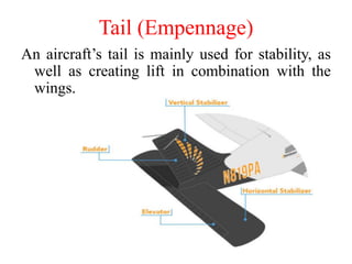
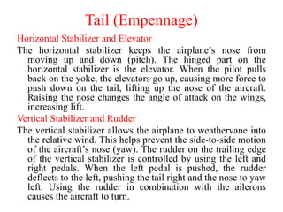
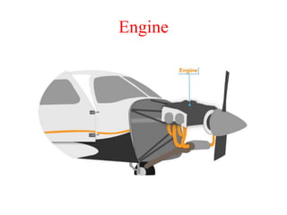
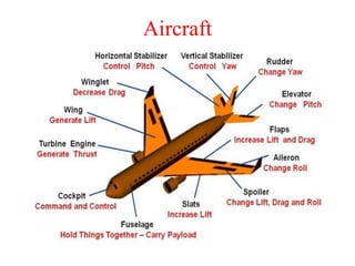
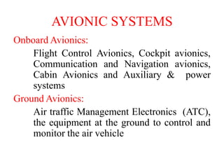
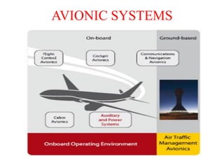
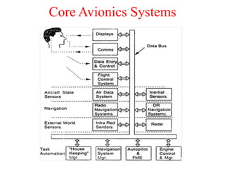
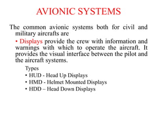
AE8751 - AVIONICS
Dr. K. Kannan, M.E., M.E., Ph.D.,
Professor & Head,
Department of Mechatronics Engineering
UNIT I
INTRODUCTION TO AVIONICS (9)
OBJECTIVES
• To introduce the basic of avionics and its need
for civil and military aircrafts
• To impart knowledge about the avionic
architecture and various avionics data buses
• To gain more knowledge on various avionics
subsystems
UNIT I
INTRODUCTION TO AVIONICS (9)
• Need for avionics in civil and military aircraft
and space systems – integrated avionics and
weapon systems – typical avionics subsystems,
design, technologies – Introduction to digital
computer and memories.
• CO1:To explain the basics of avionics and its
need for civil and military aircrafts.
Aircraft
Fuselage
The plane’s body, or fuselage, holds the aircraft
together, with pilots sitting at the front of the
fuselage, passengers and cargo in the back.
This is similar to a car’s dashboard, providing the
pilot with information about the flight, the engine
and the circumstances of the aircraft. Depending
on the aviation electronics (avionics) installed in
an aircraft this may be on an interactive screen or
using the typical ‘6 Pack’ for key pieces of
information.
• Altimeter, Airspeed Indicator, Vertical Speed
Indicator, Attitude Indicator, Heading Indicator,
Turn Coordinator.
Cockpit
Instrument Panel
Cockpit
Pilot seats
In the cockpit are two seats, one for the pilot and the
other for the co-pilot.
Rudder pedals
Rudder pedals control yaw in flight and are used for
steering on the ground during a taxi.
Overhead panel
The overhead panel contains aircraft systems, such as
air conditioning, electrical, fuel and hydraulics.
Side consoles
Side consoles are for communication instruments and
documentation, depending on the aircraft.
Cockpit
Wings
An aircraft’s wings are critical to flight through
the production of lift, but they have many parts
of the wing to control this lift amount and
direction.
Aircraft Rotations
Wings
Ailerons
Ailerons are located on the trailing edge of the wing to
control the roll of a plane. When a pilot turns to the left in
the cockpit, the left aileron goes up, reducing lift on that
side, and the right aileron goes down, increasing lift
causing that side to rise. This causes the plane to roll to
the left and begin a turn.
Flaps
Flaps, like ailerons, are located on the trailing edge of the
wing. Unlike ailerons, the flaps move symmetrically on
each side and create more lift and drag. Flaps are
typically used during takeoff and landing, when aircraft
speeds are lower, to create additional lift and reduce stall
speeds.
Winglet
On an airliner, the tip of the wing is bent up. This is known
as a winglet. Winglets were created to reduce induced
drag.
Slats
Slats are similar to flaps, only located at the front of the
wing (a leading-edge device) and change a wing’s shape
temporarily to increase lift.
Spoilers
Spoilers are used to help the aircraft descend and reduces the
lift component of an airfoil. This allows the plane to
descend and lose altitude without gaining airspeed.
Wings
Tail (Empennage)
An aircraft’s tail is mainly used for stability, as
well as creating lift in combination with the
wings.
Tail (Empennage)
Horizontal Stabilizer and Elevator
The horizontal stabilizer keeps the airplane’s nose from
moving up and down (pitch). The hinged part on the
horizontal stabilizer is the elevator. When the pilot pulls
back on the yoke, the elevators go up, causing more force to
push down on the tail, lifting up the nose of the aircraft.
Raising the nose changes the angle of attack on the wings,
increasing lift.
Vertical Stabilizer and Rudder
The vertical stabilizer allows the airplane to weathervane into
the relative wind. This helps prevent the side-to-side motion
of the aircraft’s nose (yaw). The rudder on the trailing edge
of the vertical stabilizer is controlled by using the left and
right pedals. When the left pedal is pushed, the rudder
deflects to the left, pushing the tail right and the nose to yaw
left. Using the rudder in combination with the ailerons
causes the aircraft to turn.
Engine
The engine(s) or power plant creates thrust needed
for the plane to fly. There are two types of aircraft
engines, reciprocating and turbine.
In reciprocating engines, compressed air is mixed
with fuel and ignited by an electric spark. The
exhaust gases leaves through the back of the
engine through the manifold. The engine spins the
propeller which then creates thrust to move the
plane forward.
With a turbine engine, the action of compressing air,
mixing with fuel, ignition and exhaust are similar
but occur inline. In this case the power is
generated by the air being exhausted from the
engine.
Engine
Propeller
An aircraft’s propeller(s) are airfoils installed
vertically to create thrust to drive the plane
forward. Attached to the engine, they spin
quickly, creating lift from the pressure
difference they create, only instead of this lift
causing the plane to move upwards, it drives
the plane forward creating thrust. This thrust
and forward motion in turn causes air to pass
over the wings, creating the vertical lift.
Propeller
Landing Gear
Landing gear is located under the belly of the
plane consisting of a wheel and strut to soften
impact with the ground and may be retractable
into the fuselage. Tricycle type wheels are
common for general aviation with one wheel at
the front and two behind or the reverse for tail
wheels with two wheels at the front of the
plane and one under the tail.
Landing Gear
Aircraft
Various Civilian Aircrafts
1. Boeing - 727, 737, 747, 757, 767 - Boeing
Seatle, USA
2. A300, A310, A318 to A321, A330, A340 -
Airbus, German
3. DC-3,DC-10 - Douglas – California
4. Falcon 50, 900, 2000 - Dassault Aviations,
France
Various Civilian Aircrafts
Avionic companies
• Honeywell, USA-Supplier of Avionic systems
• Bendix & King, USA- MFD, GPS
• Baker Electronics, USA -PILOT audio systems
• Rockwell Collins, USA- Aerospace & Defense
communication
• Thales, France - Aerospace & Defense
communication
• Garmin, USA-GPS systems
• Sagem, France -Avionic Recorders and Pilot
components
Various Flight Phases
Definitions
Course - The angle aircraft makes with a fixed
reference, true North-0° being North, true
North-90° being East
Heading- The direction of the aircraft's nose
pointing ; North- 0*, East – 90*, South -180*
and West -270* degrees
Track - The actual path followed by the aircraft
from A to B in a given scheme.
Military Aircrafts
Any type of aircraft adapted for military use is called as
Military Aircrafts.
Fighter aircraft, aircraft designed primarily to secure
control of essential airspace by destroying enemy
aircraft in combat. The opposition may consist of
fighters of equal capability or of bombers carrying
protective armament. For such purposes fighters must
be capable of the highest possible performance in
order to be able to out fly and out maneuver opposing
fighters. Above all, they must be armed with
specialized weapons capable of hitting and destroying
enemy aircraft.
Military Aircrafts - Fighter
Bomber, are designed to drop bombs on surface targets.
Military Aircrafts - Bomber
Helicopter is an aircraft with one or more power-driven
horizontal propellers of rotors that enable it to take
off and land vertically, to move in any direction, or to
remain stationary in the air.
Military Aircrafts - Helicopter
Unmanned aerial vehicle (UAV) that is guided
autonomously or by remote control or both and that
carries sensors, target designators, offensive
ordnance, or electronic transmitters designed to
interfere with or destroy enemy targets.
Military Aircrafts - UAV
Aeronautics
Aeronautics is the science or art involved with
the study, design and manufacturing of
air flight capable machines, and the techniques
of operating aircraft and rockets within
atmosphere. The overall aeronautics system is
classified into 4 important sub systems. They
are
Air Frame System, Vehicle System,
Mission System and Avionics System
Aeronautical Sub Systems
The sub systems of aeronautics are,
– Air frame system which is a complex and
integrated set of structural components that
supports the mass of systems and passengers, and
carries loads and stresses throughout the structure.
– Vehicle System is also known as aircraft system or
General Systems or Utility System. Many of these
systems are common to both civil and military
aircraft. They are a mixture of systems with very
different characteristics.
Aeronautical Sub Systems
The sub systems of aeronautics are,
- The mission systems which gain information
about the outside world from active and
passive sensors and process this information to
form intelligence. It is used in military
aircrafts.
- The avionic systems which are common to
both civil and military aircraft. The majority of
the systems collect, process, transfer and
respond to data.
MISSION SYSTEMS
The military aircraft requires a range of sensors and
computing to enable the crew to prosecute
designated missions. The following are the major
systems of a mission system:
•Attack or surveillance radar to provide
information on hostile and friendly targets.
•Electro-optical sensors to provide a passive
surveillance of targets.
•Electronic support measures (ESM) to provide
emitter information, range and bearing of hostile
transmitters
• Magnetic anomaly detector (MAD) to confirm the
presence of large metallic objects under the sea surface.
Military MAD equipment is used to search for minerals
by detecting their disturbance of the normal earth-field.
• Acoustic sensors to provide a means of detecting and
tracking the passage of under water objects.
• Mission computing to collate the sensor information
and to provide a fused data picture to the cockpit or
mission crew stations.
• Defensive aids to provide a means of detecting missile
attack and deploying countermeasures
MISSION SYSTEMS
AVIONIC SYSTEMS
Avionics is Aviation Electronics
They are the electronic systems used
on aircraft, artificial satellites, and spacecraft.
Avionic systems include communications,
navigation, the display and management of
multiple systems, and the hundreds of systems
that are fitted to aircraft to perform individual
functions.
Onboard Avionics:
Flight Control Avionics, Cockpit avionics,
Communication and Navigation avionics,
Cabin Avionics and Auxiliary & power
systems
Ground Avionics:
Air traffic Management Electronics (ATC),
the equipment at the ground to control and
monitor the air vehicle
AVIONIC SYSTEMS
AVIONIC SYSTEMS
Core Avionics Systems
AVIONIC SYSTEMS
The common avionic systems both for civil and
military aircrafts are
• Displays provide the crew with information and
warnings with which to operate the aircraft. It
provides the visual interface between the pilot and
the aircraft systems.
Types
• HUD - Head Up Displays
• HMD - Helmet Mounted Displays
• HDD – Head Down Displays
Displays
Communication System
It provides the two way communication between the Air
Traffic Control (ground bases) & the aircraft or
between aircrafts. Communications also connect the
flight deck to the passengers. A Radio Transmitter and
Receiver was the first avionics system installed in an
aircraft. The different types of frequencies used for
several ranges are given below.
- Long Range Communication, High Frequency (2 –
30 MHz)
- Medium Range Communication, Very High
Frequency (30 – 100 MHz)
- Military Aircraft, Ultra High Frequency (250 – 400
MHz)
- Satellite Communications
• Weather radar to provide information on
weather conditions ahead of the aircraft.
• Secondary Surveillance Radar to provide
information on the aircraft identification and
height to air traffic is a radar system used in air
traffic control (ATC), that detects and
measures the position of aircraft
• Ground proximity warning system
(GPWS)/Terrain avoidance warning
system(TAWS) to reduce the risk of aircraft
flying into the ground or into high ground
Communication System
Air Traffic Control
Data Entry and Control System
• It is essential for the crew to interact with the avionic
system.
• Examples are
– Keyboards
– Touch Panels
– Direct voice Input,
– Voice warning systems and so on.
Data Entry and Control System
• Distance measuring equipment (DME) is a
transponder-based radio navigation technology
that measures slant range distance by timing
the propagation delay of VHF or UHF radio
signals.
• Air data measurement to provide information
to other systems on altitude, air speed, outside
air temperature and Mach number.
• Accident data recorder to continuously record
specified aircraft parameters for use in analysis
of serious incidents.
Data Entry and Control System
• Instrument Landing Systems or Microwave Landing
System is used for approach guidance to the airfield.
• Cockpit voice recorder to continuously record
specified aircrew speech for use in analysis of serious
incidents.
• Internal lighting to provide a balanced lighting
solution on the flight deck for all panels and displays.
Flight Control System
• It uses the electronic system in two areas.
(i) Auto Stabilization
– Pitch Auto Stabilizer System
– Yaw Auto Stabilizer System
– Roll Auto Stabilizer System
(ii) FBW Flight Control Systems
It provides continuous automatic stabilization
of the aircraft by computer control of the
control surfaces from appropriate motion
sensors.
Aircraft State Sensor Systems
• For control and navigation of the aircraft the air data
quantities are essential. Air Data Quantities are,
– Altitude
– Calibrated Airspeed Vertical speed
– True Airspeed
– Mach Number
– Airstream Incidence Angle.
• The air data computing system computes these quantities
from the outputs of sensors which measure the static and
total pressure and the outside air temperature.
Inertial Reference System
The aircraft attitude and the direction in which it
is heading are provided by the inertial sensor
systems
Comprise a set of gyros and accelerometers
which measures the aircraft’s angular and
linear motion.
Radio Navigation System
• The Radio Navigation system provides Navigation
Information such as Aircraft’s position, Ground
speed, Track angle. Types are
– Dead Reckoning Systems
– Position Fixing Systems
• DR Navigation systems derive the vehicle’s present
position by estimating the distance travelled from a
known position from knowledge of the speed and
direction of the vehicle.
Types of DR Navigation systems
Types of DR Navigation systems are,
i) Inertial Navigation systems
- Most Accurate
ii) Doppler / Heading Reference Systems
- Used in Helicopters
iii) Air Data / Heading Reference Systems
- Low Accuracy when compared to the
above systems
Position Fixing Navigation Systems
• In this Position Fixing Systems, Satellite or ground
based transmitter is used to transmit the signal and it
was received by the receiver in the aircraft. According
to the received signals a supporting computer is used
to derive the aircraft’s position. The Prime Position
Fixing System used in aircraft is GPS.
Outside World Sensor Systems
These systems comprise both radar and infrared
sensor which enables all weather and night
time operation.
Radar Systems
Fighter Aircrafts Radars
Infrared Systems
Radar Systems
• Radar Systems
- Weather Radar detects water droplets, cloud
turbulence and gives warning about storms.
• Fighter Aircrafts Radars
- Multi Mode Radars for ground attack role and
interception role. The Radar must be able to
detect aircraft upto 100 miles away and track
several aircraft simultaneously (12 aircraft’s).
The Radar must have a look down capability to
track low flying aircraft below it.
Infrared Systems
It is used to provide a video picture of the thermal
image scene of the outside world by using fixed
Forward Looking Infra Red (FLIR) sensor or a
gimbaled IR imaging sensor.
The thermal image picture at night looks similar to
the visual picture in day time, but highlights heat
sources such as vehicle engines.
FLIR can also be installed in civil aircraft to provide
enhanced vision in addition with HUD.
Task Automation Systems
These systems reduce the crew workload and
enable minimum crew operation. They are
– Navigation Management System
– Flight Management System
– Engine Control and Management
– House Keeping Management
Navigation Management System
It comprises the operation of all radio navigation
aid systems and the combination of data from
all navigation sources such as GPS and INS
systems, to provide the best estimation of the
aircraft position and ground speed.
Flight Management Systems
The FMS tasks are given below.
(i) Flight Planning
(ii) Navigation Management
(iii) Engine control to maintain the planned speed
(iv) Control of Aircraft Flight Path
(v) Minimizing Fuel consumption
(vi) Ensuring the aircraft is at the planned 3D
position at the planned time slot (for Air Traffic
Control).
Engine Control and Management
Modern jet engines are having the Full Authority Digital
Engine Control System (FADEC). This controls flow
of fuel. This control system ensures the engine’s
temperature, speed and acceleration in control.
Engine health monitoring system record a wide range of
parameters, so it will give early warning of engine
performance deterioration, excessive wear, fatigue
damage, high vibrations, excessive temperature etc.,
House Keeping Management
Automation of the background task which are essential
for the aircraft’s safe and efficient operation. They are
i) Fuel management
ii) Electrical power supply management
iii) Hydraulic power supply management
iv) Cabin / Cockpit pressurization systems
v) Environmental control systems
vi) Warning systems
vii) Maintenance and monitoring systems.
NEED FOR AVIONICS
• To enable the flight crew to carry out the aircraft
mission safely and efficiently.
• For civil airliner, the mission is carrying
passengers to their destination.
• For military aircraft, the mission is intercepting a
hostile aircraft, attacking a ground target,
reconnaissance or maritime patrol.
NEED FOR AVIONICS
in Civil Aircraft
• For better flight control, performing computations
and increased control over flight control surfaces.
• For navigation, provide information using sensors
like Altitude and Head Reference System (AHRS).
• Provide air data like altitude, atmospheric pressure,
temperature, etc.
• Reduce crew workload.
• Increased safety for crew and passengers.
• Reduction in aircraft weight which can be translated
into increased number of passengers or long range.
• All weather operation
• Reduction in aircraft maintenance cost.
NEED FOR AVIONICS
in Military Aircraft
• Avionics in fighter aircraft eliminates the need for
a second crew member like navigator, observer
etc., which helps in reducing the training costs.
• For Stealth technology- less visible to Radar, IR,
Sonar, and other detection methods
• A single seat fighter is lighter and costs less than
an equivalent two seat version.
• Improved aircraft performance, control and better
handling.
• Reduction in maintenance costs.
• Secure communication.
• Fly-by-wire communication system used for
space vehicle’s altitude and translation control.
• Sensors used in the spacecraft for obtaining
data.
• Autopilot redundancy system.
• On-board computers used in satellites for
processing the data.
NEED FOR AVIONICS
in Space System
INTEGRATED AVIONICS SYSTEM
The combination, interconnection and control of the
individual sub-systems so that the overall system can
carry out its tasks effectively are referred to as
integrated system.
The first major step towards integrating avionic system
was taken in 1950s with the establishment of the
weapon system concept.
The integration of avionic sub-systems in civil aircraft
was taken in 1950s with the adoption of ARINC
specifications. ARINC defines systems and equipment
specifications in terms of functional requirements and
physical dimensions and electrical interfaces.
INTEGRATED AVIONICS and
WEAPON SYSTEM
The Avionics and Weapon System (AWS) in any
modern day fighter aircraft enables the pilot to
perform various mission functions such as
‘Programme Evaluation Review Technique’, or
‘PERT’ networks, and ‘Critical Path Methods,
or CPM analysis’.
Functional Requirement of AWS
• Receive Inputs from sensors, communication
systems, Radio navigation systems, Identification
system, Missiles, Electronic counter measures
system, Pilot controls.
• Computation of required parameters for
Navigation and Fire control.
• Transferring the computed results to displays,
Audio system and weapons.
• Controlling of weapon launch / Firing.
• Control / Co-ordinate / manage sensors optimally.
Sensors in AWS
A device which detects or measures a physical
property and records, indicates, or otherwise
responds to it.
In AWS, the sensors includes Radars, Inertial
Navigation System, Air Data System, Forward
Looking Infrared Sensor, etc.,.
Communication Systems in AWS
It is a digital Data link / Voice Link system for
transmission of short messages between
aircraft and ground stations via air band radio
or satellite.
Radio Navigation & IFF Systems
• Tactical Air Navigation (TACAN) is a Ultra
High Frequency Navigation system.
• Identification Friend or Foe (IFF) is designed
for command and control. It identifies the
friendly targets but not hostile ones.
Electronic Counter Measures Systems
Radar warning receiver,
Self-protection jammer,
Offensive jammer.
Self Protection Jammer – It is used to prevent
detection by enemy radar by jamming the
signal of hostile radar
Parameters for
Navigation and Fire control
Navigation Algorithms are used to guide the
steer point
Fire Control Algorithms are used for aiming
Weapon and launching the Missile.
Integrated Modular Architecture
A real time Computer Network Airborne system
(modular architecture) consisting of various
computing modules, with different criticality levels
Features are
1. A Dedicated Avionic System
2. Full Cockpit Control and Display System
3. Acoustic Warnings and tones to Crew
4. Autonomous Navigation system’
5. Full Plant Management feature
6. Monitoring and Diagnostic features.
AVIONIC SUBSYSTEMS
AVIONIC SUBSYSTEMS
• The subsystems of Avionics are Navigation,
Communication and Surveillance.
• Navigation is the field of study that focuses on the
process of monitoring and controlling the movement of
a craft or vehicle from one place to another.
• Communication is the art of conveying meanings from
one entity or group to another through the use of
mutually understood signs, symbols and semiotic rules.
• Surveillance is the process of monitoring the behavior
for the purpose of managing or directing.
AVIONICS SYSTEM DESIGN
Starting point for designing a digital avionics system is
a clear understanding of the mission requirements.
The three stages of avionics system design are:
Conceptual design
Preliminary design
Detailed design
Conceptual design considerations
• What will it do?
• How will it do?
• What is the general arrangement of parts?
The end result of conceptual design is an artist’s
or engineer’s conception of the vehicle /
product.
Example: Clay model of an automobile.
Preliminary design considerations
• How big will it be?
• How much will it weight?
• What engines will it use?
• How much fuel or propellant will it use?
• How much will it cost?
Detailed design considerations
• How many parts will it have?
• What shape will they be?
• What materials?
• How will it be made?
• How will the parts be joined?
• How will technology advancements (e.g.
lightweight material, advanced airfoils,
improved engines, etc.) impact the design?
DESIGN and TECHNOLOGY
Specific things to be considered while designing an
Avionics Systems are,
(i) Functional Requirements
(ii) Cost
(iii) Required Safety level
(iv) Selection of Design
- Allocation of functions to sub-systems
- Identification of failure modes and its effects
(v) Implementation, Testing and Evaluation
(vi) Validation
(vii) Reliability
(viii) Flexibility
(ix) Weight and (x) Power
System Architectures
Centralized
– Signal conditioning and computations are done by
computers in an avionics bay and the signals are
transmitted over one way data bus.
Advantages:
Simple design,
Software can be written easily.
Disadvantages
Long data buses are required,
Possibility for damage.
System Architectures
Federated
Sharing of input, sensor data and computed results
over data buses.
Distributed
Multiple processors are used for computing the task
under real time basis. This Architecture is used in
modern avionics system.
Memory
Thank You

AE8751-UnitI.pdf

  • 1.
    AE8751 - AVIONICS Dr.K. Kannan, M.E., M.E., Ph.D., Professor & Head, Department of Mechatronics Engineering UNIT I INTRODUCTION TO AVIONICS (9)
  • 2.
    OBJECTIVES • To introducethe basic of avionics and its need for civil and military aircrafts • To impart knowledge about the avionic architecture and various avionics data buses • To gain more knowledge on various avionics subsystems
  • 3.
    UNIT I INTRODUCTION TOAVIONICS (9) • Need for avionics in civil and military aircraft and space systems – integrated avionics and weapon systems – typical avionics subsystems, design, technologies – Introduction to digital computer and memories. • CO1:To explain the basics of avionics and its need for civil and military aircrafts.
  • 4.
  • 5.
    Fuselage The plane’s body,or fuselage, holds the aircraft together, with pilots sitting at the front of the fuselage, passengers and cargo in the back.
  • 6.
    This is similarto a car’s dashboard, providing the pilot with information about the flight, the engine and the circumstances of the aircraft. Depending on the aviation electronics (avionics) installed in an aircraft this may be on an interactive screen or using the typical ‘6 Pack’ for key pieces of information. • Altimeter, Airspeed Indicator, Vertical Speed Indicator, Attitude Indicator, Heading Indicator, Turn Coordinator. Cockpit Instrument Panel
  • 7.
  • 8.
    Pilot seats In thecockpit are two seats, one for the pilot and the other for the co-pilot. Rudder pedals Rudder pedals control yaw in flight and are used for steering on the ground during a taxi. Overhead panel The overhead panel contains aircraft systems, such as air conditioning, electrical, fuel and hydraulics. Side consoles Side consoles are for communication instruments and documentation, depending on the aircraft. Cockpit
  • 9.
    Wings An aircraft’s wingsare critical to flight through the production of lift, but they have many parts of the wing to control this lift amount and direction.
  • 10.
  • 11.
    Wings Ailerons Ailerons are locatedon the trailing edge of the wing to control the roll of a plane. When a pilot turns to the left in the cockpit, the left aileron goes up, reducing lift on that side, and the right aileron goes down, increasing lift causing that side to rise. This causes the plane to roll to the left and begin a turn. Flaps Flaps, like ailerons, are located on the trailing edge of the wing. Unlike ailerons, the flaps move symmetrically on each side and create more lift and drag. Flaps are typically used during takeoff and landing, when aircraft speeds are lower, to create additional lift and reduce stall speeds.
  • 12.
    Winglet On an airliner,the tip of the wing is bent up. This is known as a winglet. Winglets were created to reduce induced drag. Slats Slats are similar to flaps, only located at the front of the wing (a leading-edge device) and change a wing’s shape temporarily to increase lift. Spoilers Spoilers are used to help the aircraft descend and reduces the lift component of an airfoil. This allows the plane to descend and lose altitude without gaining airspeed. Wings
  • 13.
    Tail (Empennage) An aircraft’stail is mainly used for stability, as well as creating lift in combination with the wings.
  • 14.
    Tail (Empennage) Horizontal Stabilizerand Elevator The horizontal stabilizer keeps the airplane’s nose from moving up and down (pitch). The hinged part on the horizontal stabilizer is the elevator. When the pilot pulls back on the yoke, the elevators go up, causing more force to push down on the tail, lifting up the nose of the aircraft. Raising the nose changes the angle of attack on the wings, increasing lift. Vertical Stabilizer and Rudder The vertical stabilizer allows the airplane to weathervane into the relative wind. This helps prevent the side-to-side motion of the aircraft’s nose (yaw). The rudder on the trailing edge of the vertical stabilizer is controlled by using the left and right pedals. When the left pedal is pushed, the rudder deflects to the left, pushing the tail right and the nose to yaw left. Using the rudder in combination with the ailerons causes the aircraft to turn.
  • 15.
    Engine The engine(s) orpower plant creates thrust needed for the plane to fly. There are two types of aircraft engines, reciprocating and turbine. In reciprocating engines, compressed air is mixed with fuel and ignited by an electric spark. The exhaust gases leaves through the back of the engine through the manifold. The engine spins the propeller which then creates thrust to move the plane forward. With a turbine engine, the action of compressing air, mixing with fuel, ignition and exhaust are similar but occur inline. In this case the power is generated by the air being exhausted from the engine.
  • 16.
  • 17.
    Propeller An aircraft’s propeller(s)are airfoils installed vertically to create thrust to drive the plane forward. Attached to the engine, they spin quickly, creating lift from the pressure difference they create, only instead of this lift causing the plane to move upwards, it drives the plane forward creating thrust. This thrust and forward motion in turn causes air to pass over the wings, creating the vertical lift.
  • 18.
  • 19.
    Landing Gear Landing gearis located under the belly of the plane consisting of a wheel and strut to soften impact with the ground and may be retractable into the fuselage. Tricycle type wheels are common for general aviation with one wheel at the front and two behind or the reverse for tail wheels with two wheels at the front of the plane and one under the tail.
  • 20.
  • 21.
  • 22.
    Various Civilian Aircrafts 1.Boeing - 727, 737, 747, 757, 767 - Boeing Seatle, USA 2. A300, A310, A318 to A321, A330, A340 - Airbus, German 3. DC-3,DC-10 - Douglas – California 4. Falcon 50, 900, 2000 - Dassault Aviations, France
  • 23.
  • 24.
    Avionic companies • Honeywell,USA-Supplier of Avionic systems • Bendix & King, USA- MFD, GPS • Baker Electronics, USA -PILOT audio systems • Rockwell Collins, USA- Aerospace & Defense communication • Thales, France - Aerospace & Defense communication • Garmin, USA-GPS systems • Sagem, France -Avionic Recorders and Pilot components
  • 25.
  • 26.
    Definitions Course - Theangle aircraft makes with a fixed reference, true North-0° being North, true North-90° being East Heading- The direction of the aircraft's nose pointing ; North- 0*, East – 90*, South -180* and West -270* degrees Track - The actual path followed by the aircraft from A to B in a given scheme.
  • 27.
    Military Aircrafts Any typeof aircraft adapted for military use is called as Military Aircrafts. Fighter aircraft, aircraft designed primarily to secure control of essential airspace by destroying enemy aircraft in combat. The opposition may consist of fighters of equal capability or of bombers carrying protective armament. For such purposes fighters must be capable of the highest possible performance in order to be able to out fly and out maneuver opposing fighters. Above all, they must be armed with specialized weapons capable of hitting and destroying enemy aircraft.
  • 28.
  • 29.
    Bomber, are designedto drop bombs on surface targets. Military Aircrafts - Bomber
  • 30.
    Helicopter is anaircraft with one or more power-driven horizontal propellers of rotors that enable it to take off and land vertically, to move in any direction, or to remain stationary in the air. Military Aircrafts - Helicopter
  • 31.
    Unmanned aerial vehicle(UAV) that is guided autonomously or by remote control or both and that carries sensors, target designators, offensive ordnance, or electronic transmitters designed to interfere with or destroy enemy targets. Military Aircrafts - UAV
  • 32.
    Aeronautics Aeronautics is thescience or art involved with the study, design and manufacturing of air flight capable machines, and the techniques of operating aircraft and rockets within atmosphere. The overall aeronautics system is classified into 4 important sub systems. They are Air Frame System, Vehicle System, Mission System and Avionics System
  • 33.
    Aeronautical Sub Systems Thesub systems of aeronautics are, – Air frame system which is a complex and integrated set of structural components that supports the mass of systems and passengers, and carries loads and stresses throughout the structure. – Vehicle System is also known as aircraft system or General Systems or Utility System. Many of these systems are common to both civil and military aircraft. They are a mixture of systems with very different characteristics.
  • 34.
    Aeronautical Sub Systems Thesub systems of aeronautics are, - The mission systems which gain information about the outside world from active and passive sensors and process this information to form intelligence. It is used in military aircrafts. - The avionic systems which are common to both civil and military aircraft. The majority of the systems collect, process, transfer and respond to data.
  • 35.
    MISSION SYSTEMS The militaryaircraft requires a range of sensors and computing to enable the crew to prosecute designated missions. The following are the major systems of a mission system: •Attack or surveillance radar to provide information on hostile and friendly targets. •Electro-optical sensors to provide a passive surveillance of targets. •Electronic support measures (ESM) to provide emitter information, range and bearing of hostile transmitters
  • 36.
    • Magnetic anomalydetector (MAD) to confirm the presence of large metallic objects under the sea surface. Military MAD equipment is used to search for minerals by detecting their disturbance of the normal earth-field. • Acoustic sensors to provide a means of detecting and tracking the passage of under water objects. • Mission computing to collate the sensor information and to provide a fused data picture to the cockpit or mission crew stations. • Defensive aids to provide a means of detecting missile attack and deploying countermeasures MISSION SYSTEMS
  • 37.
    AVIONIC SYSTEMS Avionics isAviation Electronics They are the electronic systems used on aircraft, artificial satellites, and spacecraft. Avionic systems include communications, navigation, the display and management of multiple systems, and the hundreds of systems that are fitted to aircraft to perform individual functions.
  • 38.
    Onboard Avionics: Flight ControlAvionics, Cockpit avionics, Communication and Navigation avionics, Cabin Avionics and Auxiliary & power systems Ground Avionics: Air traffic Management Electronics (ATC), the equipment at the ground to control and monitor the air vehicle AVIONIC SYSTEMS
  • 39.
  • 40.
  • 41.
    AVIONIC SYSTEMS The commonavionic systems both for civil and military aircrafts are • Displays provide the crew with information and warnings with which to operate the aircraft. It provides the visual interface between the pilot and the aircraft systems. Types • HUD - Head Up Displays • HMD - Helmet Mounted Displays • HDD – Head Down Displays
  • 42.
  • 43.
    Communication System It providesthe two way communication between the Air Traffic Control (ground bases) & the aircraft or between aircrafts. Communications also connect the flight deck to the passengers. A Radio Transmitter and Receiver was the first avionics system installed in an aircraft. The different types of frequencies used for several ranges are given below. - Long Range Communication, High Frequency (2 – 30 MHz) - Medium Range Communication, Very High Frequency (30 – 100 MHz) - Military Aircraft, Ultra High Frequency (250 – 400 MHz) - Satellite Communications
  • 44.
    • Weather radarto provide information on weather conditions ahead of the aircraft. • Secondary Surveillance Radar to provide information on the aircraft identification and height to air traffic is a radar system used in air traffic control (ATC), that detects and measures the position of aircraft • Ground proximity warning system (GPWS)/Terrain avoidance warning system(TAWS) to reduce the risk of aircraft flying into the ground or into high ground Communication System
  • 45.
  • 46.
    Data Entry andControl System • It is essential for the crew to interact with the avionic system. • Examples are – Keyboards – Touch Panels – Direct voice Input, – Voice warning systems and so on.
  • 47.
    Data Entry andControl System • Distance measuring equipment (DME) is a transponder-based radio navigation technology that measures slant range distance by timing the propagation delay of VHF or UHF radio signals. • Air data measurement to provide information to other systems on altitude, air speed, outside air temperature and Mach number. • Accident data recorder to continuously record specified aircraft parameters for use in analysis of serious incidents.
  • 48.
    Data Entry andControl System • Instrument Landing Systems or Microwave Landing System is used for approach guidance to the airfield. • Cockpit voice recorder to continuously record specified aircrew speech for use in analysis of serious incidents. • Internal lighting to provide a balanced lighting solution on the flight deck for all panels and displays.
  • 49.
    Flight Control System •It uses the electronic system in two areas. (i) Auto Stabilization – Pitch Auto Stabilizer System – Yaw Auto Stabilizer System – Roll Auto Stabilizer System (ii) FBW Flight Control Systems It provides continuous automatic stabilization of the aircraft by computer control of the control surfaces from appropriate motion sensors.
  • 50.
    Aircraft State SensorSystems • For control and navigation of the aircraft the air data quantities are essential. Air Data Quantities are, – Altitude – Calibrated Airspeed Vertical speed – True Airspeed – Mach Number – Airstream Incidence Angle. • The air data computing system computes these quantities from the outputs of sensors which measure the static and total pressure and the outside air temperature.
  • 51.
    Inertial Reference System Theaircraft attitude and the direction in which it is heading are provided by the inertial sensor systems Comprise a set of gyros and accelerometers which measures the aircraft’s angular and linear motion.
  • 52.
    Radio Navigation System •The Radio Navigation system provides Navigation Information such as Aircraft’s position, Ground speed, Track angle. Types are – Dead Reckoning Systems – Position Fixing Systems • DR Navigation systems derive the vehicle’s present position by estimating the distance travelled from a known position from knowledge of the speed and direction of the vehicle.
  • 53.
    Types of DRNavigation systems Types of DR Navigation systems are, i) Inertial Navigation systems - Most Accurate ii) Doppler / Heading Reference Systems - Used in Helicopters iii) Air Data / Heading Reference Systems - Low Accuracy when compared to the above systems
  • 54.
    Position Fixing NavigationSystems • In this Position Fixing Systems, Satellite or ground based transmitter is used to transmit the signal and it was received by the receiver in the aircraft. According to the received signals a supporting computer is used to derive the aircraft’s position. The Prime Position Fixing System used in aircraft is GPS.
  • 55.
    Outside World SensorSystems These systems comprise both radar and infrared sensor which enables all weather and night time operation. Radar Systems Fighter Aircrafts Radars Infrared Systems
  • 56.
    Radar Systems • RadarSystems - Weather Radar detects water droplets, cloud turbulence and gives warning about storms. • Fighter Aircrafts Radars - Multi Mode Radars for ground attack role and interception role. The Radar must be able to detect aircraft upto 100 miles away and track several aircraft simultaneously (12 aircraft’s). The Radar must have a look down capability to track low flying aircraft below it.
  • 57.
    Infrared Systems It isused to provide a video picture of the thermal image scene of the outside world by using fixed Forward Looking Infra Red (FLIR) sensor or a gimbaled IR imaging sensor. The thermal image picture at night looks similar to the visual picture in day time, but highlights heat sources such as vehicle engines. FLIR can also be installed in civil aircraft to provide enhanced vision in addition with HUD.
  • 58.
    Task Automation Systems Thesesystems reduce the crew workload and enable minimum crew operation. They are – Navigation Management System – Flight Management System – Engine Control and Management – House Keeping Management
  • 59.
    Navigation Management System Itcomprises the operation of all radio navigation aid systems and the combination of data from all navigation sources such as GPS and INS systems, to provide the best estimation of the aircraft position and ground speed.
  • 60.
    Flight Management Systems TheFMS tasks are given below. (i) Flight Planning (ii) Navigation Management (iii) Engine control to maintain the planned speed (iv) Control of Aircraft Flight Path (v) Minimizing Fuel consumption (vi) Ensuring the aircraft is at the planned 3D position at the planned time slot (for Air Traffic Control).
  • 61.
    Engine Control andManagement Modern jet engines are having the Full Authority Digital Engine Control System (FADEC). This controls flow of fuel. This control system ensures the engine’s temperature, speed and acceleration in control. Engine health monitoring system record a wide range of parameters, so it will give early warning of engine performance deterioration, excessive wear, fatigue damage, high vibrations, excessive temperature etc.,
  • 62.
    House Keeping Management Automationof the background task which are essential for the aircraft’s safe and efficient operation. They are i) Fuel management ii) Electrical power supply management iii) Hydraulic power supply management iv) Cabin / Cockpit pressurization systems v) Environmental control systems vi) Warning systems vii) Maintenance and monitoring systems.
  • 63.
    NEED FOR AVIONICS •To enable the flight crew to carry out the aircraft mission safely and efficiently. • For civil airliner, the mission is carrying passengers to their destination. • For military aircraft, the mission is intercepting a hostile aircraft, attacking a ground target, reconnaissance or maritime patrol.
  • 64.
    NEED FOR AVIONICS inCivil Aircraft • For better flight control, performing computations and increased control over flight control surfaces. • For navigation, provide information using sensors like Altitude and Head Reference System (AHRS). • Provide air data like altitude, atmospheric pressure, temperature, etc. • Reduce crew workload. • Increased safety for crew and passengers. • Reduction in aircraft weight which can be translated into increased number of passengers or long range. • All weather operation • Reduction in aircraft maintenance cost.
  • 65.
    NEED FOR AVIONICS inMilitary Aircraft • Avionics in fighter aircraft eliminates the need for a second crew member like navigator, observer etc., which helps in reducing the training costs. • For Stealth technology- less visible to Radar, IR, Sonar, and other detection methods • A single seat fighter is lighter and costs less than an equivalent two seat version. • Improved aircraft performance, control and better handling. • Reduction in maintenance costs. • Secure communication.
  • 66.
    • Fly-by-wire communicationsystem used for space vehicle’s altitude and translation control. • Sensors used in the spacecraft for obtaining data. • Autopilot redundancy system. • On-board computers used in satellites for processing the data. NEED FOR AVIONICS in Space System
  • 67.
    INTEGRATED AVIONICS SYSTEM Thecombination, interconnection and control of the individual sub-systems so that the overall system can carry out its tasks effectively are referred to as integrated system. The first major step towards integrating avionic system was taken in 1950s with the establishment of the weapon system concept. The integration of avionic sub-systems in civil aircraft was taken in 1950s with the adoption of ARINC specifications. ARINC defines systems and equipment specifications in terms of functional requirements and physical dimensions and electrical interfaces.
  • 68.
    INTEGRATED AVIONICS and WEAPONSYSTEM The Avionics and Weapon System (AWS) in any modern day fighter aircraft enables the pilot to perform various mission functions such as ‘Programme Evaluation Review Technique’, or ‘PERT’ networks, and ‘Critical Path Methods, or CPM analysis’.
  • 69.
    Functional Requirement ofAWS • Receive Inputs from sensors, communication systems, Radio navigation systems, Identification system, Missiles, Electronic counter measures system, Pilot controls. • Computation of required parameters for Navigation and Fire control. • Transferring the computed results to displays, Audio system and weapons. • Controlling of weapon launch / Firing. • Control / Co-ordinate / manage sensors optimally.
  • 70.
    Sensors in AWS Adevice which detects or measures a physical property and records, indicates, or otherwise responds to it. In AWS, the sensors includes Radars, Inertial Navigation System, Air Data System, Forward Looking Infrared Sensor, etc.,.
  • 71.
    Communication Systems inAWS It is a digital Data link / Voice Link system for transmission of short messages between aircraft and ground stations via air band radio or satellite.
  • 72.
    Radio Navigation &IFF Systems • Tactical Air Navigation (TACAN) is a Ultra High Frequency Navigation system. • Identification Friend or Foe (IFF) is designed for command and control. It identifies the friendly targets but not hostile ones.
  • 73.
    Electronic Counter MeasuresSystems Radar warning receiver, Self-protection jammer, Offensive jammer. Self Protection Jammer – It is used to prevent detection by enemy radar by jamming the signal of hostile radar
  • 74.
    Parameters for Navigation andFire control Navigation Algorithms are used to guide the steer point Fire Control Algorithms are used for aiming Weapon and launching the Missile.
  • 75.
    Integrated Modular Architecture Areal time Computer Network Airborne system (modular architecture) consisting of various computing modules, with different criticality levels Features are 1. A Dedicated Avionic System 2. Full Cockpit Control and Display System 3. Acoustic Warnings and tones to Crew 4. Autonomous Navigation system’ 5. Full Plant Management feature 6. Monitoring and Diagnostic features.
  • 76.
  • 77.
    AVIONIC SUBSYSTEMS • Thesubsystems of Avionics are Navigation, Communication and Surveillance. • Navigation is the field of study that focuses on the process of monitoring and controlling the movement of a craft or vehicle from one place to another. • Communication is the art of conveying meanings from one entity or group to another through the use of mutually understood signs, symbols and semiotic rules. • Surveillance is the process of monitoring the behavior for the purpose of managing or directing.
  • 78.
    AVIONICS SYSTEM DESIGN Startingpoint for designing a digital avionics system is a clear understanding of the mission requirements. The three stages of avionics system design are: Conceptual design Preliminary design Detailed design
  • 79.
    Conceptual design considerations •What will it do? • How will it do? • What is the general arrangement of parts? The end result of conceptual design is an artist’s or engineer’s conception of the vehicle / product. Example: Clay model of an automobile.
  • 80.
    Preliminary design considerations •How big will it be? • How much will it weight? • What engines will it use? • How much fuel or propellant will it use? • How much will it cost?
  • 81.
    Detailed design considerations •How many parts will it have? • What shape will they be? • What materials? • How will it be made? • How will the parts be joined? • How will technology advancements (e.g. lightweight material, advanced airfoils, improved engines, etc.) impact the design?
  • 82.
    DESIGN and TECHNOLOGY Specificthings to be considered while designing an Avionics Systems are, (i) Functional Requirements (ii) Cost (iii) Required Safety level (iv) Selection of Design - Allocation of functions to sub-systems - Identification of failure modes and its effects (v) Implementation, Testing and Evaluation (vi) Validation (vii) Reliability (viii) Flexibility (ix) Weight and (x) Power
  • 83.
    System Architectures Centralized – Signalconditioning and computations are done by computers in an avionics bay and the signals are transmitted over one way data bus. Advantages: Simple design, Software can be written easily. Disadvantages Long data buses are required, Possibility for damage.
  • 84.
    System Architectures Federated Sharing ofinput, sensor data and computed results over data buses. Distributed Multiple processors are used for computing the task under real time basis. This Architecture is used in modern avionics system.
  • 85.
  • 86.