

Recommended
More Related Content
What's hot
What's hot (20)
Viewers also liked
Viewers also liked (17)
Similar to Quick reference guide ans
Similar to Quick reference guide ans (20)
Recently uploaded
Recently uploaded (20)
Quick reference guide ans
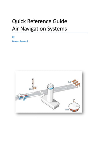
- 1. Quick Reference Guide Air Navigation Systems By Zameer Basha.S Quick Reference Guide Air Navigation Systems
- 2. This page left blank intentionally
- 3. Preface The general information contained on the following pages is provided for use as ‘Quick reference’. It has been compiled from a variety of sources. Additional information can be found else where in the specified manuals of the equipments mentioned. I have spent most of my career in the Air Traffic Control (ATC) and Air Traffic Management (ATM) environment specialising in the engineering and maintenance including the Installation, Commissioning, Flight Testing, Customer Training and Customer Support in Voice Communication & Control System (VCCS), Instrument Landing Systems (ILS), Distance Measuring Equipment (DME), Doppler VHF Omni Directional Range (DVOR), Digital- Automatic Terminal Information System(D-ATIS) and Metrological Specific Equipment (MET). This Quick reference guide may be useful for beginner and for those who need an idea about the Navaids system. Please feel free to write any enhancement and corrections for this guide, so that I can add or modify. Zameer Basha.S E-mail: zbasha2000@gmail.com
- 4. Table of Contents 1. Introduction --------- 1 A. Frequency Bands --------- 1 2. Instrument Landing System (ILS) --------- 2 A. Frequency of operation --------- 2 B. Localizer(LLZ) --------- 2 a) Types of localizer --------- 2 C. Glide Path (GP) --------- 3 a) Types of Glide Path --------- 3 3. Marker Beacons (MB) --------- 5 A. Frequency of Operation --------- 5 4. Distance Measuring Equipment (DME) --------- 6 A. Specifications of DME --------- 7 B. Working Sequence of DME --------- 7 5. Microwave Landing system (MLS) --------- 9 A. Frequency of Operation --------- 9 B. Operation --------- 9 a) Horizontal Position --------- 9 b) Glide Slope Location --------- 10 c) Flare --------- 10 d) Back Azimuth --------- 10 e) DME --------- 10 f) Transmission of Auxiliary Data --------- 10 6. The GNSS landing system (GLS) --------- 11 A. Operation --------- 11 B. Advantages of GLS --------- 13 7. Very High Frequency Omni-Directional Range (VOR) --------- 14 A. Frequency of Operation --------- 14 B. Doppler VOR (DVOR) --------- 15 8. Non-Directional Beacon (NDB) --------- 16 A. Frequency of Operation --------- 16 9. References --------- 17
- 5. Quick Reference Guide – Air Navigation Systems 1 Introduction Air-navigation systems are used to determine the position of an aircraft with respect to the surface of the earth and to provide accurate landing guidance for the aircrafts and also for on-route positioning of an aircraft. Air navigation ensures that an aircraft is guided along trajectory determined by the flight route and profile according to a prescribed plan that regulates the flight condition from takeoff to landing at a prescribed time. For aircraft precision runway approach there are various types of landing systems are available. The present and future landing technologies available are as follows Instrument Landing System (ILS) Microwave Landing System (MLS) GNSS Landing System (GLS) The details of each landing system mentioned above described in the following pages. A. Frequency Bands Radio frequencies lie within a relatively narrow range of the electro-magnetic spectrum between approximately 10 KHz and 300GHz.This range is divided in to bands, more or less in accordance with the propagation characteristics of the frequencies. These frequency bands are as follows Band Description Frequency Range VLF Very Low Frequency 0-30 kHz LF Low Frequency 30 kHz-300 kHz MF Medium Frequency 300 kHz-3 MHz HF High Frequency 3 MHz-30 MHz VHF Very High Frequency 30 MHz-300MHz UHF Ultra High Frequency 300MHz-3 GHz* SHF Super High Frequency 3 GHz-30 GHz EHF Extremely High Frequency 30 GHz-300 GHz *200MHz-3GHz is considered UHF in Aviation Table: Frequency Bands Frequency allocation is established to provide a clear channel separation between the various functions performed by aeronautical Navaids and communications facilities. Although a general allocation plan is recognised on a world-wide basis, variations may occur within certain ranges.
- 6. Quick Reference Guide – Air Navigation Systems 2 Instrument Landing System (ILS): Instrument Landing System (ILS) is the international standard system for approach and landing guidance. ILS was adopted by ICAO (International Civil Aviation Organization) in 1947.The ILS normally consists of VHF “Localizer” for runway centre line alignment guidance, UHF “Glide Path” for elevation guidance and “Marker Beacon” for providing key check points along the approach. At some airports, the marker beacons are replaced by a “DME” (Distance Measuring Equipment) to provide continuous reading of distance. A. Frequency of Operation: Localizer : 108 to 111.975MHz Glide Path : 328.6 to 335.4MHz B. Localizer (LLZ or LOC) The Localizer (LLZ), which provides lateral guidance, produces a course formed by the intersection of two antenna radiation patterns of equal amplitudes. One pattern is modulated by 90 Hz and the other by 150 Hz. The Course Line (CL) is the vertical plane where the 90 Hz and 150Hz modulations are equal. The signals received by the airborne receiver will produce a “fly right” indication for the pilot when the aircraft is to the left of the course in the predominately 90 Hz regions. Similarly, a “fly left” indication will be produced for the pilot on the opposite side of the course in the predominately 150 Hz region. a) Types of Localizer No matter what type of Localizer system installed, all give the same guidance to the Aircraft. Based on the type of the Airport (Cat I, II & III) and based on the location of the airport (Considering Obstructions) the type of localizer antenna system is chosen. The Localizer is available in single frequency and dual frequency with 12 Element, 16 Element, 20 Element and 24 Element Antenna System. Figure: 12ElementLocalizer Antennas
- 7. Quick Reference Guide – Air Navigation Systems 3 C. Glide Path (GP) The Glide Path (GP) produces two amplitude modulated radiation patterns in the vertical plane, which intercept at the descent angle, namely the glide path angle. Below the 150 Hz predominates giving a “Fly Up” indication. Above the glide path angle a “Fly Down” indication will be produced by the 90Hz predominance. The GP is sited about 300 meters behind the runway threshold to give the 15 to 18m threshold crossing height. The glide path angle is about 3.0°. a) Types of Glide Path Choosing the right type of Glide Path is depends on the type of the airport (Cat I, II & III) and the terrain of the runway side. To achieve a perfect GP angle the terrain in front of the Glide Path antennas should be even and should not have any variation on the terrain. The selection of GP antenna system is depends on this factor also. There are three types of GP antenna systems are available. They are M-Array (3 Element Antenna), Null Reference (2 Element Antenna) and Side band reference (2 Element Antenna). Figure: Glide Path Antenna Elements
- 8. Figure: ILS Localizer and Glide Path Signals Illustration Figure: Instrument Landing System Coverage Quick Reference Guide – Air Navigation Systems Figure: ILS Localizer and Glide Path Signals Illustration Figure: Instrument Landing System Coverage Air Navigation Systems 4
- 9. Quick Reference Guide – Air Navigation Systems 5 Marker Beacons (MB): This system comprises two or three beacons, with fan-shaped vertical radiation patterns. The function of the Outer Marker (OM) located 4 to 7 nautical miles from the runway threshold is normally to signal the start of the descent. The radiation pattern is amplitude modulated by a 400 Hz tone keyed by dashes at a speed of two dashes per second and causes a purple light to flash on the instrument panel of the aircraft. The Middle Marker (MM), nominally located at 1050 meters from the threshold, alerts the pilot to the fact that CAT-I decision height has been reached. A 1300 Hz modulation tone, keyed by alternate dots and dashes, the dots keyed at a speed of 6 dots per second and the dashes at 2 dashes per second, flashes an amber light on the instrument panel. For some configurations, an Inner Marker (IM) is used to signal CAT II decision height. The IM is normally located at a distance of 75m out to 450m from the landing threshold. A 3000 Hz modulation tone, keyed by dots at a speed of six dots per second, flashes a white light to indicate decision height. A. Frequency of Operation: Beacon Operation Frequency Modulation Frequency Inner Marker (IM) 75MHz 3000 Hz Middle Marker (MM) 75MHz 1300 Hz Outer Marker (OM) 75MHz 400Hz Figure: Location of Marker Beacons with respect to Runway
- 10. Quick Reference Guide – Air Navigation Systems 6 Distance Measuring Equipment (DME): The Distance Measuring Equipment provides an aircraft with a slant range distance from a known location. This system consists of an aircraft interrogator (a transmitter and receiver) which interrogates a ground based transponder, the frequency and Morse identification of which is known. The system provides a slant range measurement, the maximum range of which can be up to 200 to 300 nautical miles subject to power output, the height of the aircraft, and the terrain surrounding the ground based transponder. The airborne transponder is known as an interrogator and the ground based transponder provides replies to the interrogations. The ground based transponder is known as Distance Measuring Equipment (DME). The frequency band of the DME lies between 962 MHz and 1213 MHz and has a channel spacing of 1 MHz However, the interrogator is allocated 1025 MHz to 1150 MHz and thus 126 channels are available. The transponder transmits on frequencies the pairing of which is laid down by ICAO. They are matched so that they differ by exactly 63 MHz from the interrogator. To provide more channels for use in crowded air and frequency space, a further channel division has been established by introducing X and Y pulse spacing. A valid interrogation consists of two Gaussian shaped pulses of fixed duration and spacing. A valid reply similarly consists of two pulses Gaussian in shape and of a fixed spacing. In X mode the interrogation pulses are 3.5 µs wide and are separated by 12 µs. The reply pulses are of the same format. In Y mode, however, the interrogation pulses are 3.5 µs wide and are separated by 36 µs, but the reply pulses (of the same width) are separated by 30 µs. In both X and Y modes, the DME has a fixed internal delay time, nominally of 50 µs and 56 µs respectively, which is allowed for by the aircraft interrogator. DME’s are divided into two categories, En-route (used to provide positional fixes) and Terminal (to provide a distance from runway threshold). Terminal DMEs are also divided into two categories, In-line (where the DME antenna is co-located with the glide path aerial of an Instrument Landing System) and Off-set (where the antenna is positioned to one side of the runway behind the threshold position). A fixed reduction in the DME time delay is introduced to compensate for the case when the DME antenna is not physically at the threshold position. Figure: DME Working Concept
- 11. Quick Reference Guide – Air Navigation Systems 7 Figure: DME Antenna (In-Line) Figure: DME Antenna (Off Set) A. Specifications of DME: Characteristic Specification Frequency Range 962 MHz to 1213 MHz Pulse Spacing X Channel:12µsec Y Channel:36µsec Reply Delay X Channel:50µsec Y Channel:56µsec IDENT Frequency 1350 Hz B. Working Sequence of DME: 1) The DME receives the series of interrogation pulses from the aircraft and after a precise time delay (50 µsec) the ground station replies with an identical sequence of reply pulse-pairs. The replies from the ground station to the aircraft interrogator are made in a frequency 63 MHZ above or bellow the interrogator frequency. 2) The DME receiver in the aircraft receives the reply and measures the elapsed time from when it sent the interrogation until it received the reply. It subtracts the 50 microsecond delay that the ground station introduced to come up with the round trip time. From this the airborne receiver can calculate its exact distance from the ground station, given the fact that Distance =Velocity X (Time / 2) 3) The DME equipment then displays the computed distance.
- 12. Quick Reference Guide – Air Navigation Systems 8 Example: Total time between interrogation and reply: 62.36 microseconds Reply signal round-trip time: (62.36µsec - 50µsec)/2 = 6.18µsec Velocity: 3x10⁸ m/s Distance = (3x10⁸ m/s) x (6.18µsec) = 1,854 meters or 1.00108 NM Figure: DME Signal timing 4) The purpose of the 50 microsecond delay is to eliminate the possibility of uncoordinated operation when the aircraft is very close to the ground station (DME). If the ground station returned the pulse pair without a delay, then the interrogator could be still transmitting the second pulse of the pair when the reply from the first pulse was received. With the delay in place, a reply at zero nautical miles would occur at 50µsec after the interrogation. It then allows the operation of the DME in close proximity to the ground station. From this, it can figure out its exact distance from the ground station using simple arithmetic, given the fact that it takes 12.359 microseconds for a signal to go out and return one nautical mile.
- 13. Quick Reference Guide – Air Navigation Systems 9 Microwave Landing System (MLS) The Microwave Landing System (MLS) was designed to replace ILS with an advanced precision approach system that would overcome the disadvantages of ILS and also provide greater flexibility to its users. ILS System particularly had problems with frequency congestion in the places where the airports are closer to each other. ILS is limited to 40 channels and having difficulty with the density of airports increasing. They were starting to interfere with one another. Although the MLS overcame this issue but due to more advance technology GLS developing, In June of 1993 the USA and Canada decided to terminate all development of MLS in favour of differential GPS (GNSS) for future precision approach requirements. A. Frequency of Operation MLS : 5 to 5.25GHz B. Operation A minimal system would consist of an Approach Azimuth and an Elevation unit with the approach azimuth guidance of providing ± 40º angle. Fig: Microwave Landing System (MLS) Coverage a) Horizontal Position Time Referenced Scanning Beam (TRSB) is utilised in locating the runway centre line is as follows. The aircraft computes its Horizontal position in relation to the runway centre- line by measuring the time interval in microseconds between the reception the ‘to’ and ‘fro’ scanning beams. The beam starts the ‘to’ sweep at one extremity of its total scan and travels at a uniform speed to the other extremity. It then starts its ‘fro’ scan back to its start position. The time interval between the reception of the ‘to’ and ‘fro’ pulses is proportional to the angular position of the aircraft in relation to the runway on-course line. The pilot can choose
- 14. Quick Reference Guide – Air Navigation Systems 10 to fly the runway on-course line (QDM) or an approach path which he selects as a pre- determined number of degrees ± the runway direction. b) Glide Slope Location Another beam scans up and down at a uniform speed within its elevation limits. The aircraft’s position in relation to its selected glide slope angle is thus calculated in the same manner by measuring the time difference between the reception of the pulses from the up and down sweep. The transmissions from the two beams and the transmissions from the other components of the MLS system are transmitted at different intervals i.e. it uses ‘time division multiplexing’. c) Flare The Flare provides information on the actual height of the aircraft above the plane of the runway. Although the standard has been developed to provide for flare elevation, this function is not intended for future implementation d) Back Azimuth Gives overshoot and departure guidance ± 20° of runway direction up to 15° in elevation. e) DME Range along the MLS course is provided not by markers but by a DME. For Cat II and III approaches a precision DME (DME/P) that is accurate to within 100 feet must be available. f) Transmission of Auxiliary Data Apart from the above components, MLS can transmit an additional auxiliary data. This consists of: station identification system condition runway condition weather information
- 15. Quick Reference Guide – Air Navigation Systems 11 The GNSS landing system (GLS) The aviation industry is developing a new positioning and landing system based on Global Navigation Satellite System (GNSS).The GNSS landing system (GLS) integrates satellite and ground based navigation information to provide the position information required for approach and landing guidance. Potential benefits of the GLS include significantly improved takeoff and landing capability at airports worldwide and at reduced cost, improved instrument approach service at additional airports and runways and the eventual replacement of the Instrument Landing System. International Civil Aviation Organization (ICAO) approved GNSS in late 2001 an International standard for a landing system based on local correction of GNSS data to a level that would support instrument approaches. The ICAO Standards and Recommended Practices (SARPS) define the characteristics of a Ground-Based Augmentation System (GBAS) service that can be provided by an airport authority or an Air Traffic Service provider. The GBAS Service provides the radiated signal in space that can be used by suitably equipped airplanes as the basis of a GNSS landing system (GNSS).The initial SARPS support an approach service. A. Operation The GLS consists of three major elements, a global satellite constellation that support worldwide navigation position fixing, a GBAS facility at each equipped airport that provides local navigation satellite correction signals and avionics in each airplane that process and provide guidance and control based on the satellite and GBAS signals The GLS uses a navigation satellite constellation (Global Positioning System [GPS]) for the basic positioning service. The GPS constellation already is in place and improvements are planned over the coming decades. The basic positioning service is augmented locally at or near the airport through a GBAS radio transmitter facility. Because the ground facility is located at a known surveyed point, the GBAS can estimate the errors contained in the basic positioning data. Reference receivers in the GBAS compare the basic positioning data with the known position of the facility and compute corrections on a satellite-by-satellite basis. The corrections are called pseudo range corrections because the primary parameter of interest is the distance between the GBAS facility and individual satellites. The satellite constellation is continuously in motion, and satellites ascend and descend over the horizon when observed from any point on Earth. The GBAS calculates corrections for all the satellites that meet the specified in-view criteria and transmits that information to the nearby airplanes over a VHF Data Broadcast (VDB) data link. A single GBAS ground station typically provides approach and landing service to all runways at the airport where it is installed. The GBAS may even provide limited approach service to nearby airports. Each runway approach direction requires the definition of a final approach segment (FAS) to establish the desired reference path for an approach, landing, and rollout. The FAS data for each approach are determined by the GBAS service provider and typically are verified after installation of the GBAS ground station.
- 16. Quick Reference Guide – Air Navigation Systems 12 One feature that differentiates the GLS from a traditional landing system such as the ILS is the potential for multiple final approach paths, glide slope angles, and missed approach paths for a given runway. Each approach is given a unique identifier for a particular FAS, glide slope, and missed approach combination. FAS data for all approaches supported by the particular GBAS facility are transmitted to the airplane through the same high-integrity data link as the satellite range correction data (i.e., through the VDB data link). The MMRs process the pseudo range correction and FAS data to produce an ILS-like deviation indication from the final approach path. These deviations are then displayed on the pilot’s flight instruments (e.g., Primary Flight Display [PFD]) and are used by airplane systems such as the flight guidance system (e.g., autopilot and flight director) for landing guidance. Fig: GNSS Landing System (GLS) Overview
- 17. Quick Reference Guide – Air Navigation Systems 13 B. Advantages of GLS From the user perspective, the GBAS service can offer significantly better performance than an ILS. The guidance signal has much less noise because there are no beam bends caused by reflective interference (from buildings and vehicles). However, the real value of the GLS is the promise of additional or improved capabilities that the ILS cannot provide. For example, the GLS can Provide approach and takeoff guidance service to multiple runways through a single GBAS facility. Optimize runway use by reducing the size of critical protection areas for approach and takeoff operations compared with those needed for ILS. Provide more flexible taxiway or hold line placement choices. Simplify runway protection constraints. Provide more efficient airplane separation or spacing standards for air traffic service provision. Provide takeoff and departure guidance with a single GBAS facility.
- 18. Quick Reference Guide – Air Navigation Systems 14 Very High Frequency Omni-Directional Range (VOR): VOR is an abbreviation for “VHF Omni directional Radio Range”, which implies that it operates in the VHF band. Adopted by ICAO as early as 1960, VOR is a ground-based electronic system that provides azimuth information for high and low altitude routes and airport approaches. The VOR is the most widely used Navaids around the world, to support the medium and short distance routes on the actual ATS route structure. Its main characteristic is that using this directional emission signal can provide to airmen accurate information about the bearing of the VOR station the aircraft is crossing. There are 360º possible bearings and we call each one RADIAL. It is still the most commonly used short- range aid. As opposed to the NDB, which transmits a non-directional signal, the signal transmitted by the VOR contains directional information. The principle of operation is bearing measurement by phase comparison. This means that the transmitter on the ground produces and transmits a signal, or actually two separate signals, which make it possible for the receiver to determine its position in relation to the ground station by comparing the phases of these two signals. In theory, the VOR produces a number of tracks all originating at the transmitter. These tracks are called «radials» and are numbered from 1 to 360, expressed in degrees, or°. The 360°radial is the track leaving the VOR station towards the Magnetic North, and if you continue with the cardinal points, radial 090° points to the East, the180° radial to the South and the 270° radial to the West, all in relation to the magnetic North. Figure: VOR and its Radials Figure: Polar diagram A. Frequency of Operation: VOR : 108.0 to 117.95MHz
- 19. Quick Reference Guide – Air Navigation Systems 15 B. Doppler VOR (DVOR): The Doppler VOR is the second generation VOR, providing improved signal quality and accuracy. The REF signal of the DVOR is amplitude modulated, while the VAR signal is frequency modulated. This means that the modulations are opposite as compared to the conventional VOR. The frequency modulated signal is less subject to interference than the amplitude modulated signal and therefore the received signals provide a more accurate bearing determination. The Doppler Effect is created by letting the VAR signal be “electronically rotated”, on the circular placed aerials, at a speed of 30 revolutions per second. With a diameter of the circle of 13.4 meters, the radial velocity of the VAR signal will be 1264 m/s. This will create a Doppler shift, causing the frequency to increase as the signal is rotated towards the observer and reduce as it rotates away with 30 full cycles of frequency variation per second. This results in an effective FM of 30 Hz. A receiver situated at some distance in the radiation field continuously monitors the transmitter. When certain prescribed deviations are exceeded, either the IDENT is taken off, or the complete transmitter is taken off the air. We come back to this in the section Limitations and accuracy. Figure: Course alignment in the aircraft with respect to VOR Figure: DVOR Antenna
- 20. Quick Reference Guide – Air Navigation Systems 16 Non-Directional Beacon (NDB): NDB is the oldest form of radio navigation still in use. It transmits non-directional signals in the Low Frequency (LF) /Medium Frequency (MF) range (190 KHz-535 KHz). There are 4 types of NDB usages: i) Compass locator ii) Approach aids (25nmi), iii) Enroute beacon, iv) High power beacons- used in some coastal areas. NDB is used as an Enroute navigational aid. When NDB is used in conjunction with the ILS markers, it is called a Compass Locator. The airborne equipment used for receiving the NDB signal is called Automatic Direction Finder (ADF). The ADF consists of Amplitude Modulation (AM) receiver, Sense Antenna, Loop Antenna (directional antenna) and Indicator (fixed or movable card). The magnetic bearing to the station is determined in the following way using the fixed card. A. Frequency of Operation: NDB Band1 : 190 to 535 KHz (Low Power) NDB Band2 : 535 to 1750 KHz (Standard) Figure: Non Directional Beacon Antenna
- 21. Quick Reference Guide – Air Navigation Systems 17 References To prepare this reference book I went through many Journals on Navaids systems, Presentations and Projects reports available over the internet. I referred the technical broachers/manuals of Indra, Thales, Fernau and Mopiens which are available online. Apart from this I went through the following website and manuals for more information. a) https://www.wikipedia.org b) Training Manual Normarc7000B c) Fernau 2020 DME Training Manual d) Thales DME 415/435 Technical Manual Copyright © 2015 Zameer Basha S