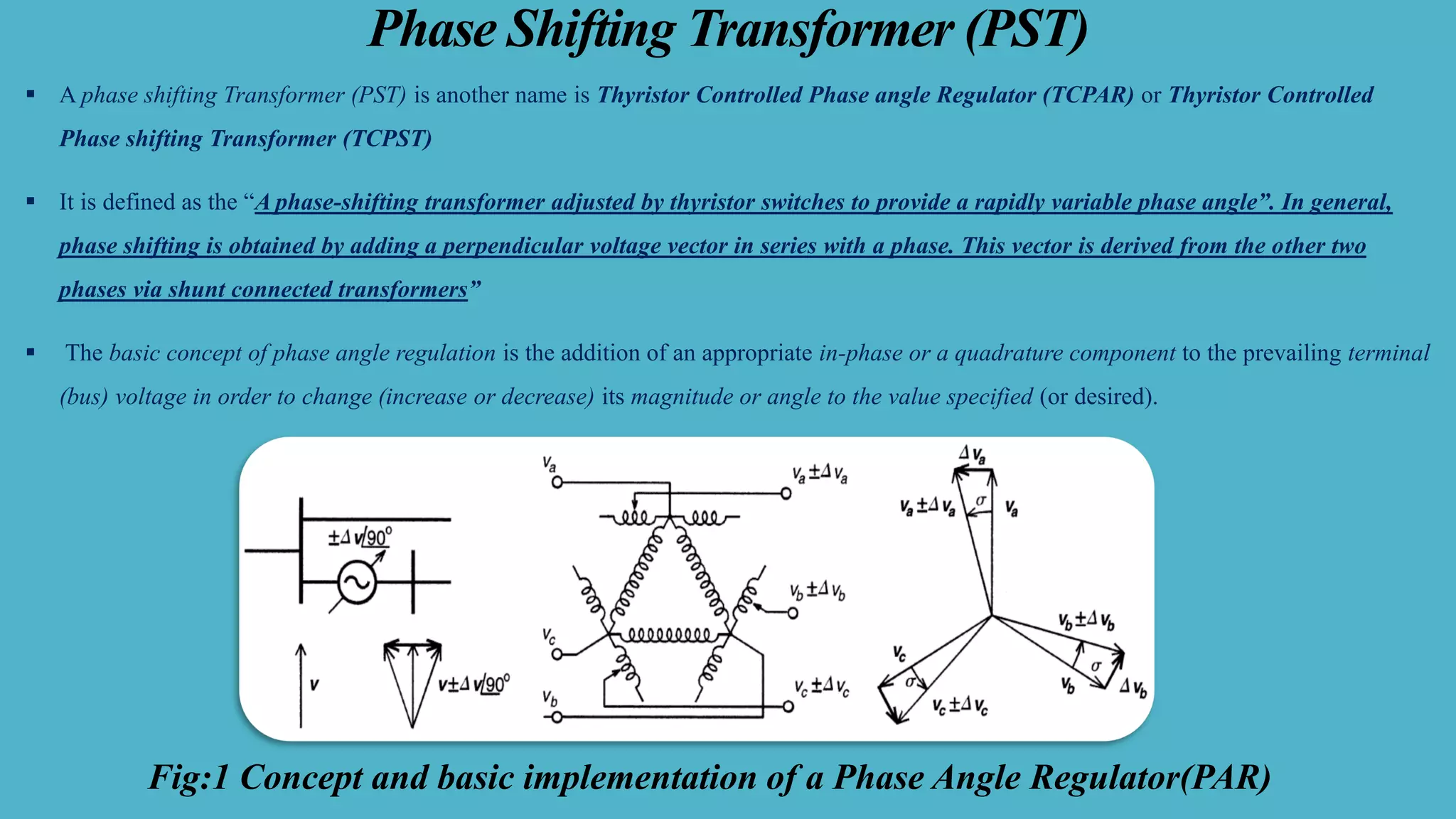
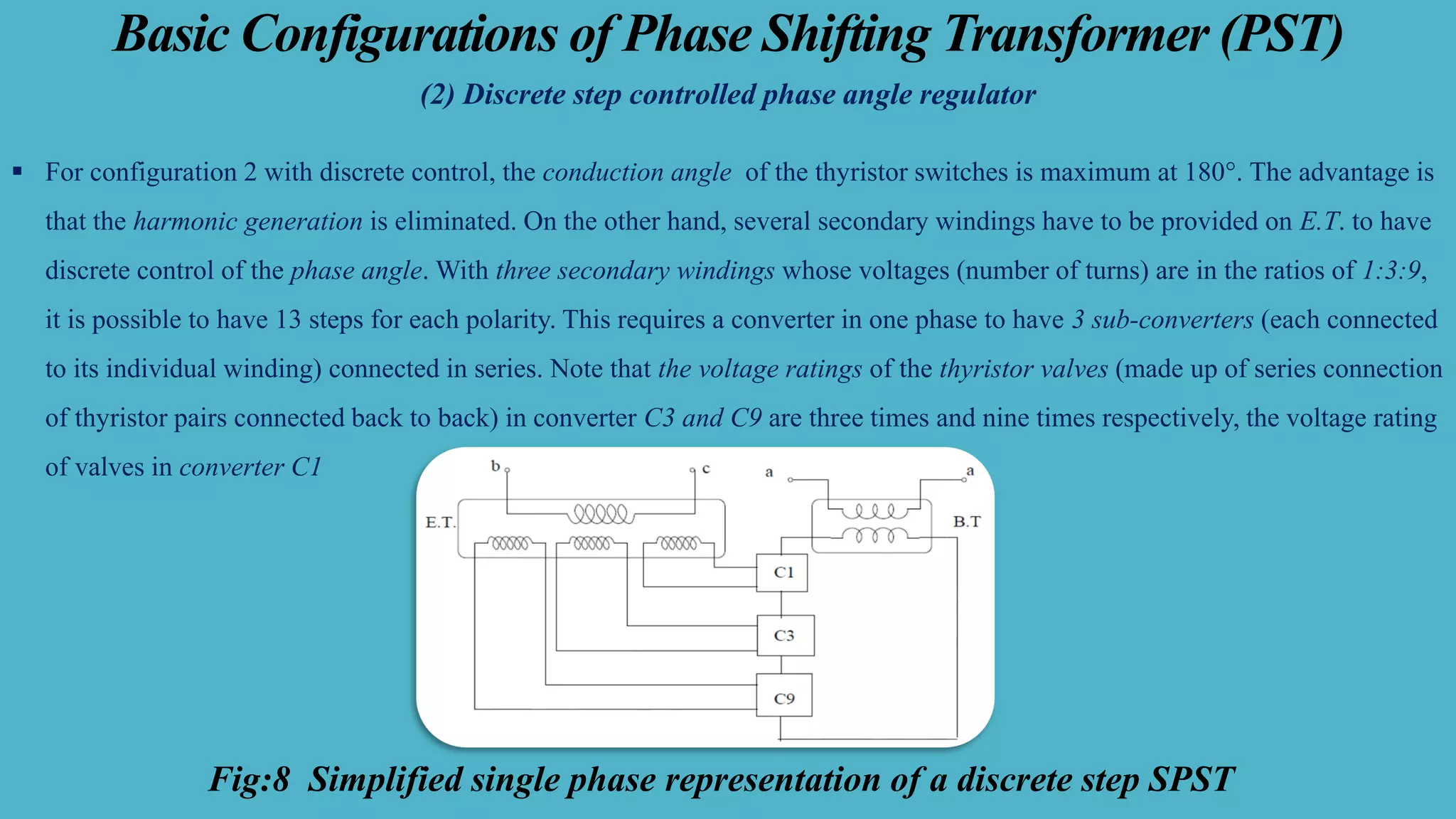
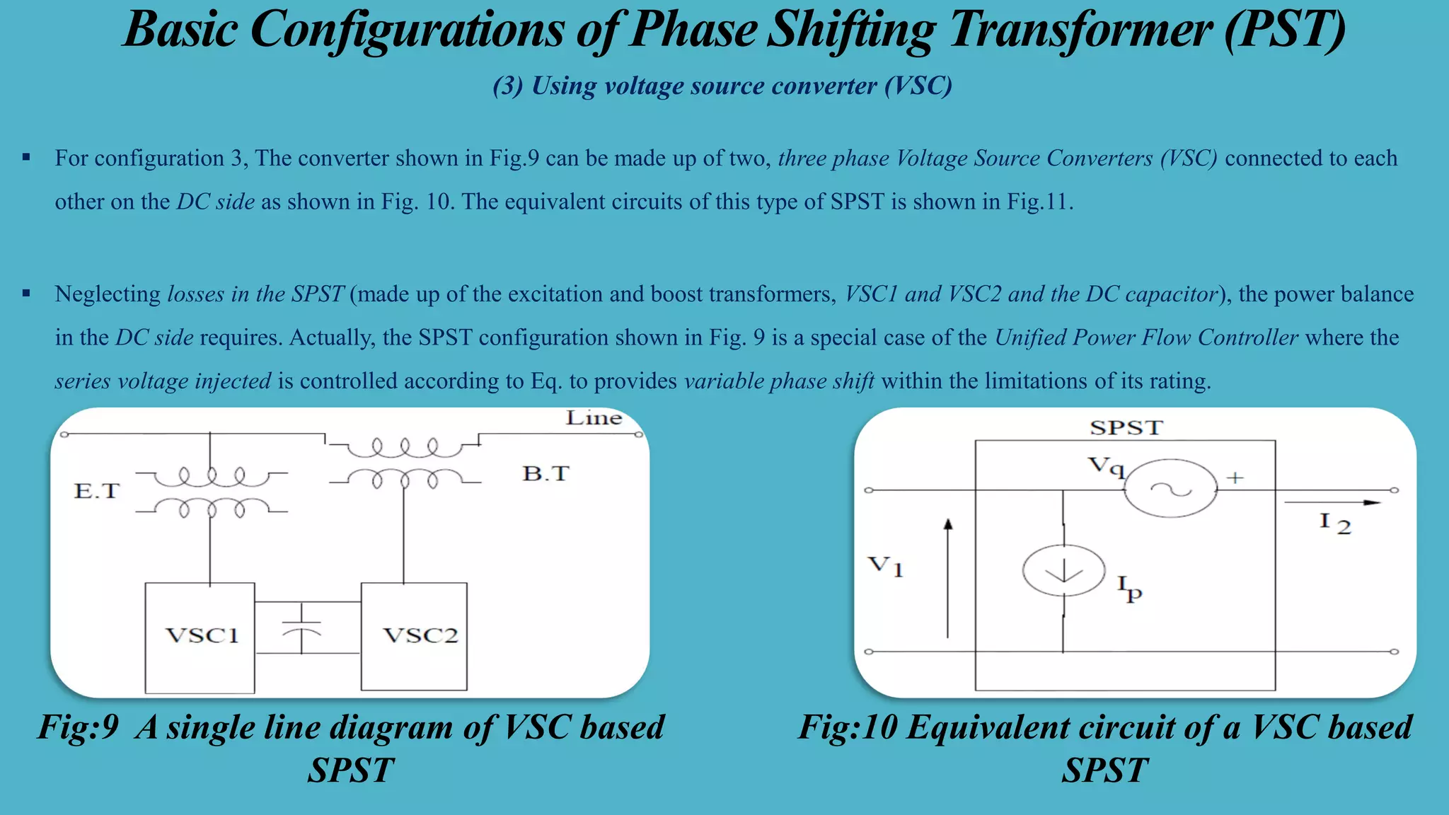
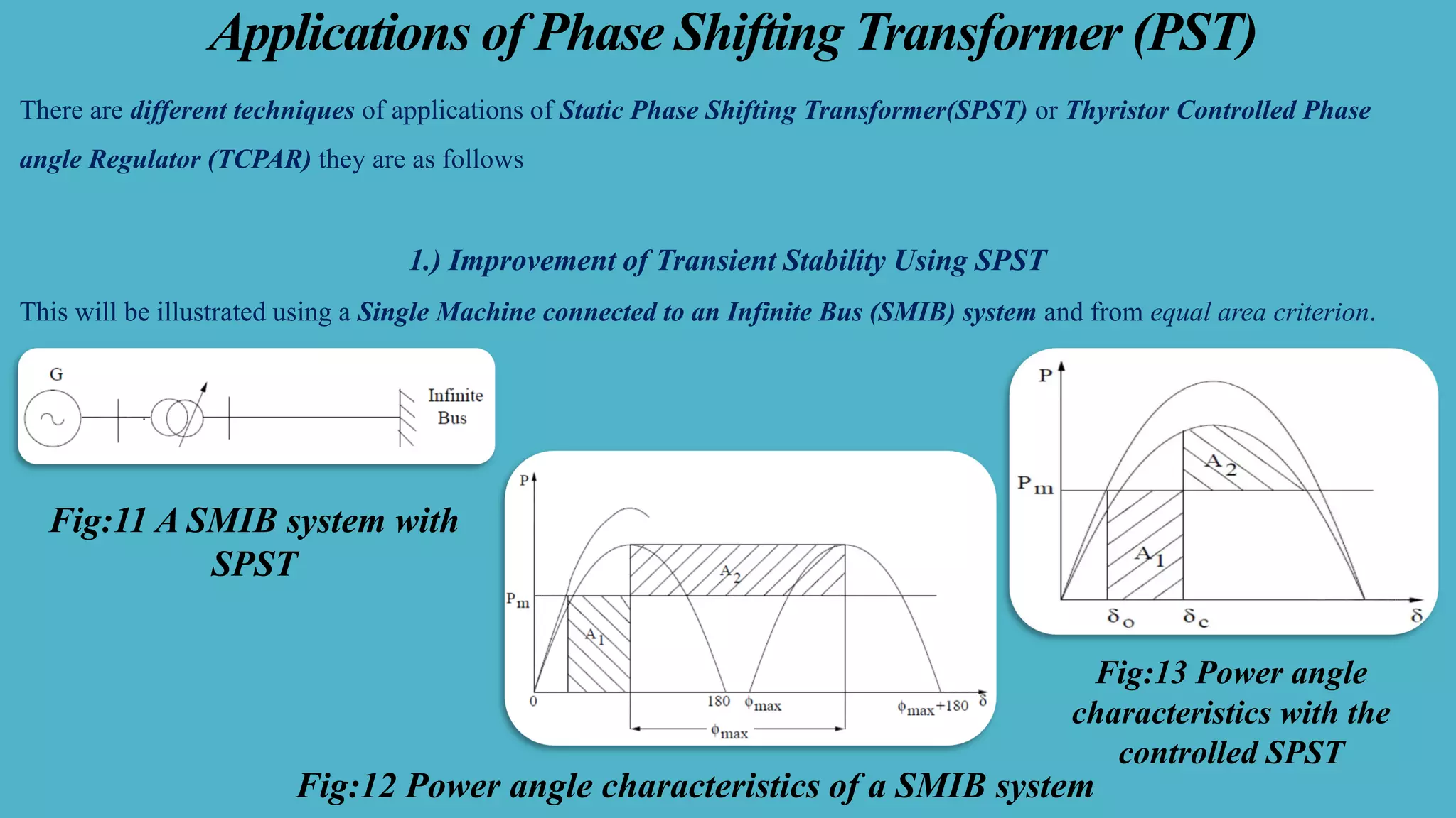
SlideShare a Scribd company logo
Flexible AC Transmission System (FACTS)
Todays Topic
Unit-2 –Description & Characteristics of Voltage Source Converter Based
FACTS Controller
Presented by
Sushovan Roy
Assistant Professor
Dream Institute of Technology, Kolkata-700104
Department of Electrical Engineering (EE)
Table of Contents
▪ Introduction to Phase Shifting Transformer (PST)
▪ Basic Operating Principle of Phase Shifting Transformer (PST) or Thyristor Controlled Phase angle Regulator (TCPAR)
▪ Basic Configurations of Phase Shifting Transformer (PST)
▪ Applications of Phase Shifting Transformer (PST)
▪ Advantages & Drawbacks of Phase Shifting Transformer (PST)
▪ Conclusions
Phase Shifting Transformer (PST)
▪ A phase shifting Transformer (PST) is another name is Thyristor Controlled Phase angle Regulator (TCPAR) or Thyristor Controlled
Phase shifting Transformer (TCPST)
▪ It is defined as the “A phase-shifting transformer adjusted by thyristor switches to provide a rapidly variable phase angle”. In general,
phase shifting is obtained by adding a perpendicular voltage vector in series with a phase. This vector is derived from the other two
phases via shunt connected transformers”
▪ The basic concept of phase angle regulation is the addition of an appropriate in-phase or a quadrature component to the prevailing terminal
(bus) voltage in order to change (increase or decrease) its magnitude or angle to the value specified (or desired).
Fig:1 Concept and basic implementation of a Phase Angle Regulator(PAR)
Phase Shifting Transformer (PST) Continued
▪ voltage regulation could, theoretically, be achieved by a synchronous, in-phase voltage source with controllable amplitude, in series with the
ac system and the regulated terminal In a similar manner, the arrangement of Figure can be used for phase angle control simply by
stipulating the injected voltage, to have a phase of ±90° relative to the system voltage, u, as illustrated in Figure 1
▪ A possible arrangement for phase angle regulator (PAR) is shown schematically in Figure 1 with the corresponding phasor diagram in
Figure For relatively small angular adjustments, the resultant angular change is approximately proportional to the injected voltage, while
the voltage magnitude remains almost constant.
▪ However, for large angular adjustments, the magnitude of the system voltage will appreciably increase and, for this reason, is often referred
to as a quadrature booster transformer (QBT) .
▪ The voltage magnitude could be maintained independent of the angular adjustment by a more complex winding arrangement. Nevertheless,
because of its relative simplicity, the QBT arrangement has typically been used in conventional phase shifting applications.
Main Outlines of Phase Shifting Transformer (PST)
Pictorial Representation of Phase Shifting Transformer (PST)
Fig:2 Thyristor-Controlled Phase-Shifting Transformer (TCPST) or Thyristor- Controlled
Phase Angle Regulator (TCPR)
Performance of PST in the Transmission line
▪ The optimal loading of transmission lines in practical power systems cannot always be achieved at the prevailing transmission angle. Such
cases would occur for example, when power between two buses is transmitted over parallel lines of different electrical length or when two
buses are inserted whose prevailing angle difference is insufficient to establish the desired power flow.
▪ The basic concept of power flow control by angle regulation, illustrated in Fig.3, is represented in terms of the usual two-machine model in
which a Phase Angle Regulator is inserted between the sending-end generator (bus) and the transmission line. Theoretically, the Phase
Angle Regulator can be considered a sinusoidal (fundamental frequency) ac voltage source with controllable amplitude and phase angle.
▪ With the phase-angle control arrangement is the effective phase angle between the sending and receiving-end voltages becomes and with
this the transmitted power P and the reactive power demands at the ends of the line.
Fig:3 Two-machine power system with a Phase Angle Regulator, corresponding phasor diagram and
transmitted power vs. angle characteristics
Classification of Phase Shifting Transformer (PST)
The classification of the phase-shifting transformer can be done based on the characteristics like the following,
▪ Direct Phase Shifting Transformer (PSTs)
The direct PSTs or direct phase-shifting transformers mainly depend on the three-phase core and its phase shift can be obtained by connecting the
windings within a suitable way
▪ Indirect Phase Shifting Transformer (PSTs)
The indirect PSTs or indirect phase-shifting transformers mainly depend on a design using two separate transformers like variable tap exciter and
another one is the series transformer. So, variable tap exciter is used to change the quadrature voltage’s amplitude whereas the series transformer
is used to insert quadrature voltage within the correct phase.
▪ Asymmetrical Phase Shifting Transformer (PSTs)
Asymmetrical phase-shifting transformers are used to generate an output voltage through changed amplitude as well as phase angle as compared
to the input voltage.
▪ Symmetrical Phase Shifting Transformer (PSTs)
Symmetrical phase-shifting transformers generate an output voltage through a changed phase angle as compared to the input voltage, however
with a similar amplitude.
Phase Shifting Transformer (PST) Used in Industry Purposes
Basic Operating Principle of Phase Shifting Transformer (PST)
▪ By applying power electronic controllers the operation of PSTs can be made fast which enables dynamic regulation of power flow and
improvement of system stability and dynamic security. These are called Static Phase Shifting Transformers (SPST) or Thyristor Controlled
Phase Angle Regulator (TCPAR) as thyristor devices have been primarily suggested to achieve the objective. However, with the advent of
Voltage Source Converter (VSC) based FACTS controllers it is also possible to apply a UPFC type device for SPST.
Fig:4 Phase Shifting Transformer(PST)
connected in a network Fig:5 The equivalent circuit referred to
primary of PST
Basic Operating Principle of Phase Shifting Transformer (PST)
Fig:6 representation for Phase Shifting
Transformer (PST)
Fig:7 Schematic diagram of a Static Phase Shifting
Transformer (SPST)or TCPAR
Basic Configurations of Phase Shifting Transformer (PST)
▪ we will consider here only 3 configurations given below for forming Thyristor Controlled Phase Angle Regulator
(1) Point-on-wave controlled phase angle regulator
(2) Discrete step controlled phase angle regulator
(3) Using voltage source converter (VSC)
(1) Point-on-wave controlled phase angle regulator (PAR)
▪ For configuration-1, a single secondary winding (per phase) of the excitation transformer (ET) is adequate as the control of the phase angle is
provided by controlling the firing (delay) angle of the thyristor switch in relation to the applied voltage.
▪ The switches T1 and T2 are used for injecting the series voltage with positives polarity (boost), whereas T3 and T4 are used to inject the
series voltage with negative or reverse polarity (buck).
▪ Thus, the phase shift of positive or negative angle can be achieved. If switches T1 and T4 (or T2 and T3) conduct, the output voltage remains
zero
Basic Configurations of Phase Shifting Transformer (PST)
(2) Discrete step controlled phase angle regulator
▪ For configuration 2 with discrete control, the conduction angle of the thyristor switches is maximum at 180°. The advantage is
that the harmonic generation is eliminated. On the other hand, several secondary windings have to be provided on E.T. to have
discrete control of the phase angle. With three secondary windings whose voltages (number of turns) are in the ratios of 1:3:9,
it is possible to have 13 steps for each polarity. This requires a converter in one phase to have 3 sub-converters (each connected
to its individual winding) connected in series. Note that the voltage ratings of the thyristor valves (made up of series connection
of thyristor pairs connected back to back) in converter C3 and C9 are three times and nine times respectively, the voltage rating
of valves in converter C1
Fig:8 Simplified single phase representation of a discrete step SPST
Basic Configurations of Phase Shifting Transformer (PST)
(3) Using voltage source converter (VSC)
▪ For configuration 3, The converter shown in Fig.9 can be made up of two, three phase Voltage Source Converters (VSC) connected to each
other on the DC side as shown in Fig. 10. The equivalent circuits of this type of SPST is shown in Fig.11.
▪ Neglecting losses in the SPST (made up of the excitation and boost transformers, VSC1 and VSC2 and the DC capacitor), the power balance
in the DC side requires. Actually, the SPST configuration shown in Fig. 9 is a special case of the Unified Power Flow Controller where the
series voltage injected is controlled according to Eq. to provides variable phase shift within the limitations of its rating.
Fig:10 Equivalent circuit of a VSC based
SPST
Fig:9 A single line diagram of VSC based
SPST
Applications of Phase Shifting Transformer (PST)
There are different techniques of applications of Static Phase Shifting Transformer(SPST) or Thyristor Controlled Phase
angle Regulator (TCPAR) they are as follows
1.) Improvement of Transient Stability Using SPST
This will be illustrated using a Single Machine connected to an Infinite Bus (SMIB) system and from equal area criterion.
Fig:11 A SMIB system with
SPST
Fig:12 Power angle characteristics of a SMIB system
Fig:13 Power angle
characteristics with the
controlled SPST
Applications of Phase Shifting Transformer (PST)
2.) Damping of Low Frequency Power Oscillations
▪ The problem of low frequency oscillations involving rotor swings is an old one, observed for the first time in the 1960s after
the introduction of the fast acting exciters and electronic AVRs (Automatic Voltage Regulator).
▪ With the advent of the power electronic controllers such as HVDC converters and SVC, an auxiliary damping controller
could be easily implemented as a Supplementary Modulation Controller (SMC) to the power or voltage scheduling controller.
▪ Generally, damping controllers for low frequency (0.2 to 2.0 Hz) oscillations can destabilize sub synchronous frequency (10-
50 Hz) oscillations due to the torsional modes. Generally, an AVR enhances synchronizing torque, but can reduce damping
torque in stressed conditions (involving maximum power transfer and weak transmission network). By designing a SMC for
the SPST based on the rotor speed signal, it is possible to enhance the damping torque and stabilize the swing mode The
SMC is expected to act only during dynamic conditions involving oscillations.
Applications of Phase Shifting Transformer (PST)
▪ some applications of SPST were considered for enhancing the transfer capability of AC ties (interconnecting two systems) they have not been
implemented, An interesting new technology introduced recently is the Variable Frequency Transformer (VFT) developed by General
Electric (U.S.A) to transfer power between two asynchronous networks. The first installation of this new technology is located at Langlois
substation, interconnecting the New York (USA) and the Hydro-Quebec (Canada) system. The technology is based on a rotary transformer
(continuously variable phase-shifting transformer) with three phase windings on both rotor and stator.
▪ A drive system adjusts the VFT rotor in order to control the phase shift between the networks through the action of a fast power
controller. The first installation at Langlois controls power transfer up to 100 MW in both directions. The development of VFT shows that a
360° PST is feasible with a rotary device which is essentially based on old technology. However, the control and drive system for VFT are
based on modern technology. It is to be noted that by regulating torque applied to the rotor, through a motor drive system, the power transfer
through the VFT is controlled. The rotor will rotate continuously if the two grids operate at different frequencies. Incidentally, the principle
of phase shifting transformer can also be applied to in-phase regulators for controlling the voltage magnitude. For example, the boost
transformer is used to inject a voltage in phase with the line voltage (which can be in positive or negative direction). Alternately, thyristor
switched tap changers are used to vary the turns ratio and control the magnitude of the secondary voltage.
Advantages Drawbacks &Applications of TCPST or TCPAR
The advantages of phase-shifting transformers include the following.
1.) The phase shift transformer allows the operator of the grid to manage loop flows that occur suddenly, so these transformers are utilized for
congestion relief.
2.) These transformers manage power flow among two grids and they cannot enhance the capability of the lines, however, if some lines are
overloaded when capacity is still obtainable on others which are parallel to them, then optimizing the flow of power these transformers can
enhance the overall capacity of the power grid.
3.) These transformers are frequently the most economic as well as consistent approach for power supply management & system design
allowing the operators of the transmission systems to acquire more out of their accessible assets.
4.) The transmission lines which exist can be loaded up toward the thermal edge without being overloaded. So, the investment within new lines
can be postponed.
The main drawbacks of phase-shifting transformers include the following
1.) the phase shifting transformer is experienced to all overvoltage and through faults,
2.) It has Higher cost & Increased size & height
Thank You all

More Related Content

What's hot

Power qualty conditioners
Power qualty conditionersPower qualty conditioners
Power qualty conditioners
Sudhanshu Goel
 
Statcom
StatcomStatcom
Statcom
jawaharramaya
 
TCSC
TCSCTCSC
Flexible AC Transmission (FACTS)
Flexible AC Transmission (FACTS)Flexible AC Transmission (FACTS)
Flexible AC Transmission (FACTS)
SHIMI S L
 
3 reactive power and voltage control
3 reactive power and voltage control3 reactive power and voltage control
3 reactive power and voltage control
8141245710
 
Power Quality Issues
Power Quality IssuesPower Quality Issues
Power Quality Issues
maneesh001
 
Distributed Generation
Distributed Generation Distributed Generation
Distributed Generation
Anshul Shrivastava
 
Voltage source Converters as a building block of HVDC and FACTS
Voltage source Converters as a building block of HVDC and FACTSVoltage source Converters as a building block of HVDC and FACTS
Voltage source Converters as a building block of HVDC and FACTS
Karthik Bharadwaj
 
Facts devices
Facts devicesFacts devices
Facts devices
Vinod Srivastava
 
INTERLINE FLOW CONTROLLER
INTERLINE FLOW CONTROLLERINTERLINE FLOW CONTROLLER
INTERLINE FLOW CONTROLLER
Nitish NIT
 
Restructuring of power grid
Restructuring of power gridRestructuring of power grid
Restructuring of power grid
Saravanan Sivamani
 
Classification Of Power System Stability
Classification Of Power System StabilityClassification Of Power System Stability
Classification Of Power System Stability
Aravind Shaji
 
Introduction to reactive power control in electrical power
Introduction to reactive power control in electrical powerIntroduction to reactive power control in electrical power
Introduction to reactive power control in electrical power
Dr.Raja R
 
An overview of FACTS devices
An overview of FACTS devicesAn overview of FACTS devices
An overview of FACTS devices
Indian Institute of Technology Guwahati
 
Power System Control And Line Compensation
Power System Control And Line CompensationPower System Control And Line Compensation
Power System Control And Line Compensation
Anakin Akshat Assal
 
voltage and power stability of hvdc system
voltage and power stability of hvdc systemvoltage and power stability of hvdc system
voltage and power stability of hvdc system
chandan kumar
 
Two area system
Two area systemTwo area system
Two area system
Balaram Das
 
Power system security and smart grid
Power system security  and  smart gridPower system security  and  smart grid
Power system security and smart grid
इन्दुभूषण कुमार
 

What's hot (20)

Power qualty conditioners
Power qualty conditionersPower qualty conditioners
Power qualty conditioners
 
Statcom
StatcomStatcom
Statcom
 
TCSC
TCSCTCSC
TCSC
 
Flexible AC Transmission (FACTS)
Flexible AC Transmission (FACTS)Flexible AC Transmission (FACTS)
Flexible AC Transmission (FACTS)
 
3 reactive power and voltage control
3 reactive power and voltage control3 reactive power and voltage control
3 reactive power and voltage control
 
Power Quality Issues
Power Quality IssuesPower Quality Issues
Power Quality Issues
 
Distributed Generation
Distributed Generation Distributed Generation
Distributed Generation
 
Voltage source Converters as a building block of HVDC and FACTS
Voltage source Converters as a building block of HVDC and FACTSVoltage source Converters as a building block of HVDC and FACTS
Voltage source Converters as a building block of HVDC and FACTS
 
Facts devices
Facts devicesFacts devices
Facts devices
 
INTERLINE FLOW CONTROLLER
INTERLINE FLOW CONTROLLERINTERLINE FLOW CONTROLLER
INTERLINE FLOW CONTROLLER
 
Restructuring of power grid
Restructuring of power gridRestructuring of power grid
Restructuring of power grid
 
Classification Of Power System Stability
Classification Of Power System StabilityClassification Of Power System Stability
Classification Of Power System Stability
 
Introduction to reactive power control in electrical power
Introduction to reactive power control in electrical powerIntroduction to reactive power control in electrical power
Introduction to reactive power control in electrical power
 
An overview of FACTS devices
An overview of FACTS devicesAn overview of FACTS devices
An overview of FACTS devices
 
DFIG_report
DFIG_reportDFIG_report
DFIG_report
 
Fc tcr.newpptx
Fc tcr.newpptxFc tcr.newpptx
Fc tcr.newpptx
 
Power System Control And Line Compensation
Power System Control And Line CompensationPower System Control And Line Compensation
Power System Control And Line Compensation
 
voltage and power stability of hvdc system
voltage and power stability of hvdc systemvoltage and power stability of hvdc system
voltage and power stability of hvdc system
 
Two area system
Two area systemTwo area system
Two area system
 
Power system security and smart grid
Power system security  and  smart gridPower system security  and  smart grid
Power system security and smart grid
 

Similar to Basic Configurations of Thyristor Controlled Phase Shifting Transformer or Phase angle Regulators

Ab34169175
Ab34169175Ab34169175
Ab34169175
IJERA Editor
 
Commutation torque ripple in bldc by sepic and npc
Commutation torque ripple in bldc by sepic and npcCommutation torque ripple in bldc by sepic and npc
Commutation torque ripple in bldc by sepic and npc
Kollimarla Pavankumar
 
An Adaptive Zero Voltage Mechanism for Boost Converter
An Adaptive Zero Voltage Mechanism for Boost ConverterAn Adaptive Zero Voltage Mechanism for Boost Converter
An Adaptive Zero Voltage Mechanism for Boost Converter
IOSR Journals
 
Implementation of FC-TCR for Reactive Power Control
Implementation of FC-TCR for Reactive Power ControlImplementation of FC-TCR for Reactive Power Control
Implementation of FC-TCR for Reactive Power Control
IOSR Journals
 
Simulation of 3-phase matrix converter using space vector modulation
Simulation of 3-phase matrix converter using space vector modulationSimulation of 3-phase matrix converter using space vector modulation
Simulation of 3-phase matrix converter using space vector modulation
IJECEIAES
 
Evolve the Controller for Static Synchronous Series Compensator Based on Cont...
Evolve the Controller for Static Synchronous Series Compensator Based on Cont...Evolve the Controller for Static Synchronous Series Compensator Based on Cont...
Evolve the Controller for Static Synchronous Series Compensator Based on Cont...
IJPEDS-IAES
 
Unit-2..pdf
Unit-2..pdfUnit-2..pdf
Unit-2..pdf
LucasMogaka
 
Combined use of tap-changing transformer and static VAR compensator for enhan...
Combined use of tap-changing transformer and static VAR compensator for enhan...Combined use of tap-changing transformer and static VAR compensator for enhan...
Combined use of tap-changing transformer and static VAR compensator for enhan...
ijsrd.com
 
A Novel Control Strategy of Indirect Matrix Converter Using Space Vector Modu...
A Novel Control Strategy of Indirect Matrix Converter Using Space Vector Modu...A Novel Control Strategy of Indirect Matrix Converter Using Space Vector Modu...
A Novel Control Strategy of Indirect Matrix Converter Using Space Vector Modu...
IJPEDS-IAES
 
Or3425552561
Or3425552561Or3425552561
Or3425552561
IJERA Editor
 
SOLID STATE TRANSFORMER - USING FLYBACK CONVERTER
SOLID STATE TRANSFORMER - USING FLYBACK CONVERTERSOLID STATE TRANSFORMER - USING FLYBACK CONVERTER
SOLID STATE TRANSFORMER - USING FLYBACK CONVERTER
Abhin Mohan
 
A320108
A320108A320108
overvoltage in distribution network
overvoltage in distribution networkovervoltage in distribution network
overvoltage in distribution network
megala venkatesan
 
A survey on Single Phase to Three Phase Cyclo-Converter fed Induction Motor
A survey on Single Phase to Three Phase Cyclo-Converter fed Induction MotorA survey on Single Phase to Three Phase Cyclo-Converter fed Induction Motor
A survey on Single Phase to Three Phase Cyclo-Converter fed Induction Motor
IJSRD
 
[IJET V2I2P30] Authors: AnkurGheewala, Jay Chanawala,Nikhil Jadav,Modi Rishit...
[IJET V2I2P30] Authors: AnkurGheewala, Jay Chanawala,Nikhil Jadav,Modi Rishit...[IJET V2I2P30] Authors: AnkurGheewala, Jay Chanawala,Nikhil Jadav,Modi Rishit...
[IJET V2I2P30] Authors: AnkurGheewala, Jay Chanawala,Nikhil Jadav,Modi Rishit...
IJET - International Journal of Engineering and Techniques
 
Performance of PWM Rectifier with Different Types of Load
Performance of PWM Rectifier with Different Types of LoadPerformance of PWM Rectifier with Different Types of Load
Performance of PWM Rectifier with Different Types of Load
ijsrd.com
 
Fuzzy logic Control & Minimizing Commutation Torque Ripple for Brushless DC M...
Fuzzy logic Control & Minimizing Commutation Torque Ripple for Brushless DC M...Fuzzy logic Control & Minimizing Commutation Torque Ripple for Brushless DC M...
Fuzzy logic Control & Minimizing Commutation Torque Ripple for Brushless DC M...
Editor IJMTER
 
Application of SVM Technique for Three Phase Three Leg Ac/Ac Converter Topology
Application of SVM Technique for Three Phase Three Leg Ac/Ac Converter TopologyApplication of SVM Technique for Three Phase Three Leg Ac/Ac Converter Topology
Application of SVM Technique for Three Phase Three Leg Ac/Ac Converter Topology
IOSR Journals
 
2 twofold mode series echoing dc dc converter for ample load
2 twofold mode series echoing dc dc converter for ample load2 twofold mode series echoing dc dc converter for ample load
2 twofold mode series echoing dc dc converter for ample loadchelliah paramasivan
 

Similar to Basic Configurations of Thyristor Controlled Phase Shifting Transformer or Phase angle Regulators (20)

Ab34169175
Ab34169175Ab34169175
Ab34169175
 
Commutation torque ripple in bldc by sepic and npc
Commutation torque ripple in bldc by sepic and npcCommutation torque ripple in bldc by sepic and npc
Commutation torque ripple in bldc by sepic and npc
 
An Adaptive Zero Voltage Mechanism for Boost Converter
An Adaptive Zero Voltage Mechanism for Boost ConverterAn Adaptive Zero Voltage Mechanism for Boost Converter
An Adaptive Zero Voltage Mechanism for Boost Converter
 
Implementation of FC-TCR for Reactive Power Control
Implementation of FC-TCR for Reactive Power ControlImplementation of FC-TCR for Reactive Power Control
Implementation of FC-TCR for Reactive Power Control
 
Simulation of 3-phase matrix converter using space vector modulation
Simulation of 3-phase matrix converter using space vector modulationSimulation of 3-phase matrix converter using space vector modulation
Simulation of 3-phase matrix converter using space vector modulation
 
Evolve the Controller for Static Synchronous Series Compensator Based on Cont...
Evolve the Controller for Static Synchronous Series Compensator Based on Cont...Evolve the Controller for Static Synchronous Series Compensator Based on Cont...
Evolve the Controller for Static Synchronous Series Compensator Based on Cont...
 
Unit-2..pdf
Unit-2..pdfUnit-2..pdf
Unit-2..pdf
 
Combined use of tap-changing transformer and static VAR compensator for enhan...
Combined use of tap-changing transformer and static VAR compensator for enhan...Combined use of tap-changing transformer and static VAR compensator for enhan...
Combined use of tap-changing transformer and static VAR compensator for enhan...
 
A Novel Control Strategy of Indirect Matrix Converter Using Space Vector Modu...
A Novel Control Strategy of Indirect Matrix Converter Using Space Vector Modu...A Novel Control Strategy of Indirect Matrix Converter Using Space Vector Modu...
A Novel Control Strategy of Indirect Matrix Converter Using Space Vector Modu...
 
Or3425552561
Or3425552561Or3425552561
Or3425552561
 
SOLID STATE TRANSFORMER - USING FLYBACK CONVERTER
SOLID STATE TRANSFORMER - USING FLYBACK CONVERTERSOLID STATE TRANSFORMER - USING FLYBACK CONVERTER
SOLID STATE TRANSFORMER - USING FLYBACK CONVERTER
 
A320108
A320108A320108
A320108
 
overvoltage in distribution network
overvoltage in distribution networkovervoltage in distribution network
overvoltage in distribution network
 
K046065864
K046065864K046065864
K046065864
 
A survey on Single Phase to Three Phase Cyclo-Converter fed Induction Motor
A survey on Single Phase to Three Phase Cyclo-Converter fed Induction MotorA survey on Single Phase to Three Phase Cyclo-Converter fed Induction Motor
A survey on Single Phase to Three Phase Cyclo-Converter fed Induction Motor
 
[IJET V2I2P30] Authors: AnkurGheewala, Jay Chanawala,Nikhil Jadav,Modi Rishit...
[IJET V2I2P30] Authors: AnkurGheewala, Jay Chanawala,Nikhil Jadav,Modi Rishit...[IJET V2I2P30] Authors: AnkurGheewala, Jay Chanawala,Nikhil Jadav,Modi Rishit...
[IJET V2I2P30] Authors: AnkurGheewala, Jay Chanawala,Nikhil Jadav,Modi Rishit...
 
Performance of PWM Rectifier with Different Types of Load
Performance of PWM Rectifier with Different Types of LoadPerformance of PWM Rectifier with Different Types of Load
Performance of PWM Rectifier with Different Types of Load
 
Fuzzy logic Control & Minimizing Commutation Torque Ripple for Brushless DC M...
Fuzzy logic Control & Minimizing Commutation Torque Ripple for Brushless DC M...Fuzzy logic Control & Minimizing Commutation Torque Ripple for Brushless DC M...
Fuzzy logic Control & Minimizing Commutation Torque Ripple for Brushless DC M...
 
Application of SVM Technique for Three Phase Three Leg Ac/Ac Converter Topology
Application of SVM Technique for Three Phase Three Leg Ac/Ac Converter TopologyApplication of SVM Technique for Three Phase Three Leg Ac/Ac Converter Topology
Application of SVM Technique for Three Phase Three Leg Ac/Ac Converter Topology
 
2 twofold mode series echoing dc dc converter for ample load
2 twofold mode series echoing dc dc converter for ample load2 twofold mode series echoing dc dc converter for ample load
2 twofold mode series echoing dc dc converter for ample load
 

Recently uploaded

Gen AI Study Jams _ For the GDSC Leads in India.pdf
Gen AI Study Jams _ For the GDSC Leads in India.pdfGen AI Study Jams _ For the GDSC Leads in India.pdf
Gen AI Study Jams _ For the GDSC Leads in India.pdf
gdsczhcet
 
Nuclear Power Economics and Structuring 2024
Nuclear Power Economics and Structuring 2024Nuclear Power Economics and Structuring 2024
Nuclear Power Economics and Structuring 2024
Massimo Talia
 
一比一原版(IIT毕业证)伊利诺伊理工大学毕业证成绩单专业办理
一比一原版(IIT毕业证)伊利诺伊理工大学毕业证成绩单专业办理一比一原版(IIT毕业证)伊利诺伊理工大学毕业证成绩单专业办理
一比一原版(IIT毕业证)伊利诺伊理工大学毕业证成绩单专业办理
zwunae
 
power quality voltage fluctuation UNIT - I.pptx
power quality voltage fluctuation UNIT - I.pptxpower quality voltage fluctuation UNIT - I.pptx
power quality voltage fluctuation UNIT - I.pptx
ViniHema
 
Runway Orientation Based on the Wind Rose Diagram.pptx
Runway Orientation Based on the Wind Rose Diagram.pptxRunway Orientation Based on the Wind Rose Diagram.pptx
Runway Orientation Based on the Wind Rose Diagram.pptx
SupreethSP4
 
space technology lecture notes on satellite
space technology lecture notes on satellitespace technology lecture notes on satellite
space technology lecture notes on satellite
ongomchris
 
Final project report on grocery store management system..pdf
Final project report on grocery store management system..pdfFinal project report on grocery store management system..pdf
Final project report on grocery store management system..pdf
Kamal Acharya
 
Water Industry Process Automation and Control Monthly - May 2024.pdf
Water Industry Process Automation and Control Monthly - May 2024.pdfWater Industry Process Automation and Control Monthly - May 2024.pdf
Water Industry Process Automation and Control Monthly - May 2024.pdf
Water Industry Process Automation & Control
 
Hybrid optimization of pumped hydro system and solar- Engr. Abdul-Azeez.pdf
Hybrid optimization of pumped hydro system and solar- Engr. Abdul-Azeez.pdfHybrid optimization of pumped hydro system and solar- Engr. Abdul-Azeez.pdf
Hybrid optimization of pumped hydro system and solar- Engr. Abdul-Azeez.pdf
fxintegritypublishin
 
Railway Signalling Principles Edition 3.pdf
Railway Signalling Principles Edition 3.pdfRailway Signalling Principles Edition 3.pdf
Railway Signalling Principles Edition 3.pdf
TeeVichai
 
CFD Simulation of By-pass Flow in a HRSG module by R&R Consult.pptx
CFD Simulation of By-pass Flow in a HRSG module by R&R Consult.pptxCFD Simulation of By-pass Flow in a HRSG module by R&R Consult.pptx
CFD Simulation of By-pass Flow in a HRSG module by R&R Consult.pptx
R&R Consult
 
Top 10 Oil and Gas Projects in Saudi Arabia 2024.pdf
Top 10 Oil and Gas Projects in Saudi Arabia 2024.pdfTop 10 Oil and Gas Projects in Saudi Arabia 2024.pdf
Top 10 Oil and Gas Projects in Saudi Arabia 2024.pdf
Teleport Manpower Consultant
 
一比一原版(SFU毕业证)西蒙菲莎大学毕业证成绩单如何办理
一比一原版(SFU毕业证)西蒙菲莎大学毕业证成绩单如何办理一比一原版(SFU毕业证)西蒙菲莎大学毕业证成绩单如何办理
一比一原版(SFU毕业证)西蒙菲莎大学毕业证成绩单如何办理
bakpo1
 
The role of big data in decision making.
The role of big data in decision making.The role of big data in decision making.
The role of big data in decision making.
ankuprajapati0525
 
Student information management system project report ii.pdf
Student information management system project report ii.pdfStudent information management system project report ii.pdf
Student information management system project report ii.pdf
Kamal Acharya
 
Standard Reomte Control Interface - Neometrix
Standard Reomte Control Interface - NeometrixStandard Reomte Control Interface - Neometrix
Standard Reomte Control Interface - Neometrix
Neometrix_Engineering_Pvt_Ltd
 
CME397 Surface Engineering- Professional Elective
CME397 Surface Engineering- Professional ElectiveCME397 Surface Engineering- Professional Elective
CME397 Surface Engineering- Professional Elective
karthi keyan
 
ML for identifying fraud using open blockchain data.pptx
ML for identifying fraud using open blockchain data.pptxML for identifying fraud using open blockchain data.pptx
ML for identifying fraud using open blockchain data.pptx
Vijay Dialani, PhD
 
The Benefits and Techniques of Trenchless Pipe Repair.pdf
The Benefits and Techniques of Trenchless Pipe Repair.pdfThe Benefits and Techniques of Trenchless Pipe Repair.pdf
The Benefits and Techniques of Trenchless Pipe Repair.pdf
Pipe Restoration Solutions
 
Investor-Presentation-Q1FY2024 investor presentation document.pptx
Investor-Presentation-Q1FY2024 investor presentation document.pptxInvestor-Presentation-Q1FY2024 investor presentation document.pptx
Investor-Presentation-Q1FY2024 investor presentation document.pptx
AmarGB2
 

Recently uploaded (20)

Gen AI Study Jams _ For the GDSC Leads in India.pdf
Gen AI Study Jams _ For the GDSC Leads in India.pdfGen AI Study Jams _ For the GDSC Leads in India.pdf
Gen AI Study Jams _ For the GDSC Leads in India.pdf
 
Nuclear Power Economics and Structuring 2024
Nuclear Power Economics and Structuring 2024Nuclear Power Economics and Structuring 2024
Nuclear Power Economics and Structuring 2024
 
一比一原版(IIT毕业证)伊利诺伊理工大学毕业证成绩单专业办理
一比一原版(IIT毕业证)伊利诺伊理工大学毕业证成绩单专业办理一比一原版(IIT毕业证)伊利诺伊理工大学毕业证成绩单专业办理
一比一原版(IIT毕业证)伊利诺伊理工大学毕业证成绩单专业办理
 
power quality voltage fluctuation UNIT - I.pptx
power quality voltage fluctuation UNIT - I.pptxpower quality voltage fluctuation UNIT - I.pptx
power quality voltage fluctuation UNIT - I.pptx
 
Runway Orientation Based on the Wind Rose Diagram.pptx
Runway Orientation Based on the Wind Rose Diagram.pptxRunway Orientation Based on the Wind Rose Diagram.pptx
Runway Orientation Based on the Wind Rose Diagram.pptx
 
space technology lecture notes on satellite
space technology lecture notes on satellitespace technology lecture notes on satellite
space technology lecture notes on satellite
 
Final project report on grocery store management system..pdf
Final project report on grocery store management system..pdfFinal project report on grocery store management system..pdf
Final project report on grocery store management system..pdf
 
Water Industry Process Automation and Control Monthly - May 2024.pdf
Water Industry Process Automation and Control Monthly - May 2024.pdfWater Industry Process Automation and Control Monthly - May 2024.pdf
Water Industry Process Automation and Control Monthly - May 2024.pdf
 
Hybrid optimization of pumped hydro system and solar- Engr. Abdul-Azeez.pdf
Hybrid optimization of pumped hydro system and solar- Engr. Abdul-Azeez.pdfHybrid optimization of pumped hydro system and solar- Engr. Abdul-Azeez.pdf
Hybrid optimization of pumped hydro system and solar- Engr. Abdul-Azeez.pdf
 
Railway Signalling Principles Edition 3.pdf
Railway Signalling Principles Edition 3.pdfRailway Signalling Principles Edition 3.pdf
Railway Signalling Principles Edition 3.pdf
 
CFD Simulation of By-pass Flow in a HRSG module by R&R Consult.pptx
CFD Simulation of By-pass Flow in a HRSG module by R&R Consult.pptxCFD Simulation of By-pass Flow in a HRSG module by R&R Consult.pptx
CFD Simulation of By-pass Flow in a HRSG module by R&R Consult.pptx
 
Top 10 Oil and Gas Projects in Saudi Arabia 2024.pdf
Top 10 Oil and Gas Projects in Saudi Arabia 2024.pdfTop 10 Oil and Gas Projects in Saudi Arabia 2024.pdf
Top 10 Oil and Gas Projects in Saudi Arabia 2024.pdf
 
一比一原版(SFU毕业证)西蒙菲莎大学毕业证成绩单如何办理
一比一原版(SFU毕业证)西蒙菲莎大学毕业证成绩单如何办理一比一原版(SFU毕业证)西蒙菲莎大学毕业证成绩单如何办理
一比一原版(SFU毕业证)西蒙菲莎大学毕业证成绩单如何办理
 
The role of big data in decision making.
The role of big data in decision making.The role of big data in decision making.
The role of big data in decision making.
 
Student information management system project report ii.pdf
Student information management system project report ii.pdfStudent information management system project report ii.pdf
Student information management system project report ii.pdf
 
Standard Reomte Control Interface - Neometrix
Standard Reomte Control Interface - NeometrixStandard Reomte Control Interface - Neometrix
Standard Reomte Control Interface - Neometrix
 
CME397 Surface Engineering- Professional Elective
CME397 Surface Engineering- Professional ElectiveCME397 Surface Engineering- Professional Elective
CME397 Surface Engineering- Professional Elective
 
ML for identifying fraud using open blockchain data.pptx
ML for identifying fraud using open blockchain data.pptxML for identifying fraud using open blockchain data.pptx
ML for identifying fraud using open blockchain data.pptx
 
The Benefits and Techniques of Trenchless Pipe Repair.pdf
The Benefits and Techniques of Trenchless Pipe Repair.pdfThe Benefits and Techniques of Trenchless Pipe Repair.pdf
The Benefits and Techniques of Trenchless Pipe Repair.pdf
 
Investor-Presentation-Q1FY2024 investor presentation document.pptx
Investor-Presentation-Q1FY2024 investor presentation document.pptxInvestor-Presentation-Q1FY2024 investor presentation document.pptx
Investor-Presentation-Q1FY2024 investor presentation document.pptx
 

Basic Configurations of Thyristor Controlled Phase Shifting Transformer or Phase angle Regulators

  • 1. Flexible AC Transmission System (FACTS) Todays Topic Unit-2 –Description & Characteristics of Voltage Source Converter Based FACTS Controller Presented by Sushovan Roy Assistant Professor Dream Institute of Technology, Kolkata-700104 Department of Electrical Engineering (EE)
  • 2. Table of Contents ▪ Introduction to Phase Shifting Transformer (PST) ▪ Basic Operating Principle of Phase Shifting Transformer (PST) or Thyristor Controlled Phase angle Regulator (TCPAR) ▪ Basic Configurations of Phase Shifting Transformer (PST) ▪ Applications of Phase Shifting Transformer (PST) ▪ Advantages & Drawbacks of Phase Shifting Transformer (PST) ▪ Conclusions
  • 3. Phase Shifting Transformer (PST) ▪ A phase shifting Transformer (PST) is another name is Thyristor Controlled Phase angle Regulator (TCPAR) or Thyristor Controlled Phase shifting Transformer (TCPST) ▪ It is defined as the “A phase-shifting transformer adjusted by thyristor switches to provide a rapidly variable phase angle”. In general, phase shifting is obtained by adding a perpendicular voltage vector in series with a phase. This vector is derived from the other two phases via shunt connected transformers” ▪ The basic concept of phase angle regulation is the addition of an appropriate in-phase or a quadrature component to the prevailing terminal (bus) voltage in order to change (increase or decrease) its magnitude or angle to the value specified (or desired). Fig:1 Concept and basic implementation of a Phase Angle Regulator(PAR)
  • 4. Phase Shifting Transformer (PST) Continued ▪ voltage regulation could, theoretically, be achieved by a synchronous, in-phase voltage source with controllable amplitude, in series with the ac system and the regulated terminal In a similar manner, the arrangement of Figure can be used for phase angle control simply by stipulating the injected voltage, to have a phase of ±90° relative to the system voltage, u, as illustrated in Figure 1 ▪ A possible arrangement for phase angle regulator (PAR) is shown schematically in Figure 1 with the corresponding phasor diagram in Figure For relatively small angular adjustments, the resultant angular change is approximately proportional to the injected voltage, while the voltage magnitude remains almost constant. ▪ However, for large angular adjustments, the magnitude of the system voltage will appreciably increase and, for this reason, is often referred to as a quadrature booster transformer (QBT) . ▪ The voltage magnitude could be maintained independent of the angular adjustment by a more complex winding arrangement. Nevertheless, because of its relative simplicity, the QBT arrangement has typically been used in conventional phase shifting applications.
  • 5. Main Outlines of Phase Shifting Transformer (PST)
  • 6. Pictorial Representation of Phase Shifting Transformer (PST) Fig:2 Thyristor-Controlled Phase-Shifting Transformer (TCPST) or Thyristor- Controlled Phase Angle Regulator (TCPR)
  • 7. Performance of PST in the Transmission line ▪ The optimal loading of transmission lines in practical power systems cannot always be achieved at the prevailing transmission angle. Such cases would occur for example, when power between two buses is transmitted over parallel lines of different electrical length or when two buses are inserted whose prevailing angle difference is insufficient to establish the desired power flow. ▪ The basic concept of power flow control by angle regulation, illustrated in Fig.3, is represented in terms of the usual two-machine model in which a Phase Angle Regulator is inserted between the sending-end generator (bus) and the transmission line. Theoretically, the Phase Angle Regulator can be considered a sinusoidal (fundamental frequency) ac voltage source with controllable amplitude and phase angle. ▪ With the phase-angle control arrangement is the effective phase angle between the sending and receiving-end voltages becomes and with this the transmitted power P and the reactive power demands at the ends of the line. Fig:3 Two-machine power system with a Phase Angle Regulator, corresponding phasor diagram and transmitted power vs. angle characteristics
  • 8. Classification of Phase Shifting Transformer (PST) The classification of the phase-shifting transformer can be done based on the characteristics like the following, ▪ Direct Phase Shifting Transformer (PSTs) The direct PSTs or direct phase-shifting transformers mainly depend on the three-phase core and its phase shift can be obtained by connecting the windings within a suitable way ▪ Indirect Phase Shifting Transformer (PSTs) The indirect PSTs or indirect phase-shifting transformers mainly depend on a design using two separate transformers like variable tap exciter and another one is the series transformer. So, variable tap exciter is used to change the quadrature voltage’s amplitude whereas the series transformer is used to insert quadrature voltage within the correct phase. ▪ Asymmetrical Phase Shifting Transformer (PSTs) Asymmetrical phase-shifting transformers are used to generate an output voltage through changed amplitude as well as phase angle as compared to the input voltage. ▪ Symmetrical Phase Shifting Transformer (PSTs) Symmetrical phase-shifting transformers generate an output voltage through a changed phase angle as compared to the input voltage, however with a similar amplitude.
  • 9. Phase Shifting Transformer (PST) Used in Industry Purposes
  • 10. Basic Operating Principle of Phase Shifting Transformer (PST) ▪ By applying power electronic controllers the operation of PSTs can be made fast which enables dynamic regulation of power flow and improvement of system stability and dynamic security. These are called Static Phase Shifting Transformers (SPST) or Thyristor Controlled Phase Angle Regulator (TCPAR) as thyristor devices have been primarily suggested to achieve the objective. However, with the advent of Voltage Source Converter (VSC) based FACTS controllers it is also possible to apply a UPFC type device for SPST. Fig:4 Phase Shifting Transformer(PST) connected in a network Fig:5 The equivalent circuit referred to primary of PST
  • 11. Basic Operating Principle of Phase Shifting Transformer (PST) Fig:6 representation for Phase Shifting Transformer (PST) Fig:7 Schematic diagram of a Static Phase Shifting Transformer (SPST)or TCPAR
  • 12. Basic Configurations of Phase Shifting Transformer (PST) ▪ we will consider here only 3 configurations given below for forming Thyristor Controlled Phase Angle Regulator (1) Point-on-wave controlled phase angle regulator (2) Discrete step controlled phase angle regulator (3) Using voltage source converter (VSC) (1) Point-on-wave controlled phase angle regulator (PAR) ▪ For configuration-1, a single secondary winding (per phase) of the excitation transformer (ET) is adequate as the control of the phase angle is provided by controlling the firing (delay) angle of the thyristor switch in relation to the applied voltage. ▪ The switches T1 and T2 are used for injecting the series voltage with positives polarity (boost), whereas T3 and T4 are used to inject the series voltage with negative or reverse polarity (buck). ▪ Thus, the phase shift of positive or negative angle can be achieved. If switches T1 and T4 (or T2 and T3) conduct, the output voltage remains zero
  • 13. Basic Configurations of Phase Shifting Transformer (PST) (2) Discrete step controlled phase angle regulator ▪ For configuration 2 with discrete control, the conduction angle of the thyristor switches is maximum at 180°. The advantage is that the harmonic generation is eliminated. On the other hand, several secondary windings have to be provided on E.T. to have discrete control of the phase angle. With three secondary windings whose voltages (number of turns) are in the ratios of 1:3:9, it is possible to have 13 steps for each polarity. This requires a converter in one phase to have 3 sub-converters (each connected to its individual winding) connected in series. Note that the voltage ratings of the thyristor valves (made up of series connection of thyristor pairs connected back to back) in converter C3 and C9 are three times and nine times respectively, the voltage rating of valves in converter C1 Fig:8 Simplified single phase representation of a discrete step SPST
  • 14. Basic Configurations of Phase Shifting Transformer (PST) (3) Using voltage source converter (VSC) ▪ For configuration 3, The converter shown in Fig.9 can be made up of two, three phase Voltage Source Converters (VSC) connected to each other on the DC side as shown in Fig. 10. The equivalent circuits of this type of SPST is shown in Fig.11. ▪ Neglecting losses in the SPST (made up of the excitation and boost transformers, VSC1 and VSC2 and the DC capacitor), the power balance in the DC side requires. Actually, the SPST configuration shown in Fig. 9 is a special case of the Unified Power Flow Controller where the series voltage injected is controlled according to Eq. to provides variable phase shift within the limitations of its rating. Fig:10 Equivalent circuit of a VSC based SPST Fig:9 A single line diagram of VSC based SPST
  • 15. Applications of Phase Shifting Transformer (PST) There are different techniques of applications of Static Phase Shifting Transformer(SPST) or Thyristor Controlled Phase angle Regulator (TCPAR) they are as follows 1.) Improvement of Transient Stability Using SPST This will be illustrated using a Single Machine connected to an Infinite Bus (SMIB) system and from equal area criterion. Fig:11 A SMIB system with SPST Fig:12 Power angle characteristics of a SMIB system Fig:13 Power angle characteristics with the controlled SPST
  • 16. Applications of Phase Shifting Transformer (PST) 2.) Damping of Low Frequency Power Oscillations ▪ The problem of low frequency oscillations involving rotor swings is an old one, observed for the first time in the 1960s after the introduction of the fast acting exciters and electronic AVRs (Automatic Voltage Regulator). ▪ With the advent of the power electronic controllers such as HVDC converters and SVC, an auxiliary damping controller could be easily implemented as a Supplementary Modulation Controller (SMC) to the power or voltage scheduling controller. ▪ Generally, damping controllers for low frequency (0.2 to 2.0 Hz) oscillations can destabilize sub synchronous frequency (10- 50 Hz) oscillations due to the torsional modes. Generally, an AVR enhances synchronizing torque, but can reduce damping torque in stressed conditions (involving maximum power transfer and weak transmission network). By designing a SMC for the SPST based on the rotor speed signal, it is possible to enhance the damping torque and stabilize the swing mode The SMC is expected to act only during dynamic conditions involving oscillations.
  • 17. Applications of Phase Shifting Transformer (PST) ▪ some applications of SPST were considered for enhancing the transfer capability of AC ties (interconnecting two systems) they have not been implemented, An interesting new technology introduced recently is the Variable Frequency Transformer (VFT) developed by General Electric (U.S.A) to transfer power between two asynchronous networks. The first installation of this new technology is located at Langlois substation, interconnecting the New York (USA) and the Hydro-Quebec (Canada) system. The technology is based on a rotary transformer (continuously variable phase-shifting transformer) with three phase windings on both rotor and stator. ▪ A drive system adjusts the VFT rotor in order to control the phase shift between the networks through the action of a fast power controller. The first installation at Langlois controls power transfer up to 100 MW in both directions. The development of VFT shows that a 360° PST is feasible with a rotary device which is essentially based on old technology. However, the control and drive system for VFT are based on modern technology. It is to be noted that by regulating torque applied to the rotor, through a motor drive system, the power transfer through the VFT is controlled. The rotor will rotate continuously if the two grids operate at different frequencies. Incidentally, the principle of phase shifting transformer can also be applied to in-phase regulators for controlling the voltage magnitude. For example, the boost transformer is used to inject a voltage in phase with the line voltage (which can be in positive or negative direction). Alternately, thyristor switched tap changers are used to vary the turns ratio and control the magnitude of the secondary voltage.
  • 18. Advantages Drawbacks &Applications of TCPST or TCPAR The advantages of phase-shifting transformers include the following. 1.) The phase shift transformer allows the operator of the grid to manage loop flows that occur suddenly, so these transformers are utilized for congestion relief. 2.) These transformers manage power flow among two grids and they cannot enhance the capability of the lines, however, if some lines are overloaded when capacity is still obtainable on others which are parallel to them, then optimizing the flow of power these transformers can enhance the overall capacity of the power grid. 3.) These transformers are frequently the most economic as well as consistent approach for power supply management & system design allowing the operators of the transmission systems to acquire more out of their accessible assets. 4.) The transmission lines which exist can be loaded up toward the thermal edge without being overloaded. So, the investment within new lines can be postponed. The main drawbacks of phase-shifting transformers include the following 1.) the phase shifting transformer is experienced to all overvoltage and through faults, 2.) It has Higher cost & Increased size & height