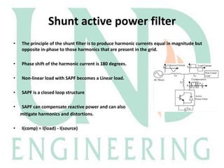
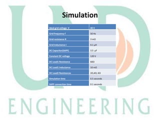
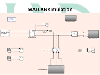
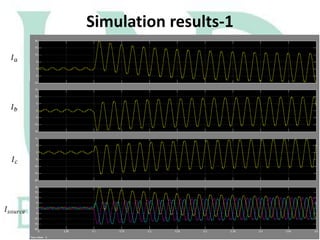
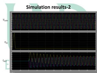
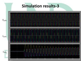
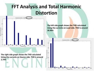
The document describes a Simulink model that was created to improve total harmonic distortion (THD) using a shunt active power filter. The model simulates a power system with a non-linear load connected to an ideal grid voltage. The shunt active power filter is connected 0.1 seconds after simulation start and works to compensate for harmonics by producing currents equal in magnitude but opposite in phase to the load harmonics. Simulation results show the THD is reduced from around 30.9% on the load side to 2.79% on the source side once the active filter is connected, below the maximum allowable limit.
![Shunt Active Power Filter
Reference [1]](https://image.slidesharecdn.com/shuntactivepowerfilterslides-140120164617-phpapp02/85/Shunt-active-power-filter-5-320.jpg)

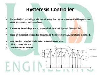
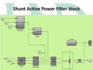
![Actual
Implementation of
p-q Theory in SAPF
These currents
and voltages are
taken as inputs to
the filter from
the line or load.
The powers to be
compensated are given
input. The compensator
should draw exactly the
given amount of current
that produces the inverse
of powers that are drawn
by the load.
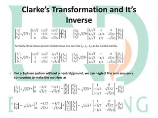
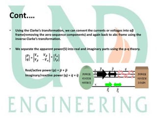
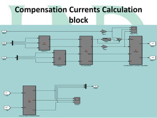
Through
transformation,
we get the real
and imaginary
power values
By applying Inverse
Clarke's
transformation, we get
the actual abc
coordinates which can
be applied to the line
again.
Reference [1]](https://image.slidesharecdn.com/shuntactivepowerfilterslides-140120164617-phpapp02/85/Shunt-active-power-filter-13-320.jpg)

![References
*1+. “Instantaneous Power Theory and Applications to Power Conditioning” by Hirofumi
Akagi, Edson Hirokazu Watanabe and Mauricio Aredes.
[2]. MATLAB and Simulink R2013b (www.mathworks.com)
[3]. H. Akagi, Y. Kanazawa and A. Nabae, “Generalized Theory of Instantaneous Reactive Power
and It’s Applications,” Transactions of the IEE-Japan, Part B, vol. 103, no.7, 1983
[4]. E. Clarke, Circuit Analysis of A-C Power Systems, Vol.1—Symmetrical and Related
Components, Wiler, 1943.
[5]. SimiPowerSystem, for use with Simulink, by MATLAB](https://image.slidesharecdn.com/shuntactivepowerfilterslides-140120164617-phpapp02/85/Shunt-active-power-filter-25-320.jpg)