The document compares different aspects of various microprocessors and computer components. It discusses the differences between 8085 and 8086 microprocessors, microcontrollers and microprocessors, memory mapped I/O vs I/O mapped I/O, RISC vs CISC processors, SIM and RIM instructions, software and hardware interrupts, 8253 and 8254 programmable interval timers, PROM vs EPROM, and the pin diagram of the 8085 microprocessor.
this is a complete summer training report on embedded sys_AVR. It aslo includes a project and its coding and other topics which are learnt in training.
SYBSC IT SEM IV EMBEDDED SYSTEMS UNIT III The 8051 MicrocontrollersArti Parab Academics
The 8051 Microcontrollers: Microcontrollers and Embedded processors, Overview of 8051 family. 8051 Microcontroller hardware, Input/output pins, Ports, and Circuits, External Memory. 8051 Programming in C: Data Types and time delay in 8051 C, I/O Programming, Logic operations, Data conversion Programs
Introduction to AI for Nonprofits with Tapp NetworkTechSoup
Dive into the world of AI! Experts Jon Hill and Tareq Monaur will guide you through AI's role in enhancing nonprofit websites and basic marketing strategies, making it easy to understand and apply.
A Strategic Approach: GenAI in EducationPeter Windle
Artificial Intelligence (AI) technologies such as Generative AI, Image Generators and Large Language Models have had a dramatic impact on teaching, learning and assessment over the past 18 months. The most immediate threat AI posed was to Academic Integrity with Higher Education Institutes (HEIs) focusing their efforts on combating the use of GenAI in assessment. Guidelines were developed for staff and students, policies put in place too. Innovative educators have forged paths in the use of Generative AI for teaching, learning and assessments leading to pockets of transformation springing up across HEIs, often with little or no top-down guidance, support or direction.
This Gasta posits a strategic approach to integrating AI into HEIs to prepare staff, students and the curriculum for an evolving world and workplace. We will highlight the advantages of working with these technologies beyond the realm of teaching, learning and assessment by considering prompt engineering skills, industry impact, curriculum changes, and the need for staff upskilling. In contrast, not engaging strategically with Generative AI poses risks, including falling behind peers, missed opportunities and failing to ensure our graduates remain employable. The rapid evolution of AI technologies necessitates a proactive and strategic approach if we are to remain relevant.
The French Revolution, which began in 1789, was a period of radical social and political upheaval in France. It marked the decline of absolute monarchies, the rise of secular and democratic republics, and the eventual rise of Napoleon Bonaparte. This revolutionary period is crucial in understanding the transition from feudalism to modernity in Europe.
For more information, visit-www.vavaclasses.com
Acetabularia Information For Class 9 .docxvaibhavrinwa19
Acetabularia acetabulum is a single-celled green alga that in its vegetative state is morphologically differentiated into a basal rhizoid and an axially elongated stalk, which bears whorls of branching hairs. The single diploid nucleus resides in the rhizoid.
2024.06.01 Introducing a competency framework for languag learning materials ...Sandy Millin
http://sandymillin.wordpress.com/iateflwebinar2024
Published classroom materials form the basis of syllabuses, drive teacher professional development, and have a potentially huge influence on learners, teachers and education systems. All teachers also create their own materials, whether a few sentences on a blackboard, a highly-structured fully-realised online course, or anything in between. Despite this, the knowledge and skills needed to create effective language learning materials are rarely part of teacher training, and are mostly learnt by trial and error.
Knowledge and skills frameworks, generally called competency frameworks, for ELT teachers, trainers and managers have existed for a few years now. However, until I created one for my MA dissertation, there wasn’t one drawing together what we need to know and do to be able to effectively produce language learning materials.
This webinar will introduce you to my framework, highlighting the key competencies I identified from my research. It will also show how anybody involved in language teaching (any language, not just English!), teacher training, managing schools or developing language learning materials can benefit from using the framework.
The Roman Empire A Historical Colossus.pdfkaushalkr1407
The Roman Empire, a vast and enduring power, stands as one of history's most remarkable civilizations, leaving an indelible imprint on the world. It emerged from the Roman Republic, transitioning into an imperial powerhouse under the leadership of Augustus Caesar in 27 BCE. This transformation marked the beginning of an era defined by unprecedented territorial expansion, architectural marvels, and profound cultural influence.
The empire's roots lie in the city of Rome, founded, according to legend, by Romulus in 753 BCE. Over centuries, Rome evolved from a small settlement to a formidable republic, characterized by a complex political system with elected officials and checks on power. However, internal strife, class conflicts, and military ambitions paved the way for the end of the Republic. Julius Caesar’s dictatorship and subsequent assassination in 44 BCE created a power vacuum, leading to a civil war. Octavian, later Augustus, emerged victorious, heralding the Roman Empire’s birth.
Under Augustus, the empire experienced the Pax Romana, a 200-year period of relative peace and stability. Augustus reformed the military, established efficient administrative systems, and initiated grand construction projects. The empire's borders expanded, encompassing territories from Britain to Egypt and from Spain to the Euphrates. Roman legions, renowned for their discipline and engineering prowess, secured and maintained these vast territories, building roads, fortifications, and cities that facilitated control and integration.
The Roman Empire’s society was hierarchical, with a rigid class system. At the top were the patricians, wealthy elites who held significant political power. Below them were the plebeians, free citizens with limited political influence, and the vast numbers of slaves who formed the backbone of the economy. The family unit was central, governed by the paterfamilias, the male head who held absolute authority.
Culturally, the Romans were eclectic, absorbing and adapting elements from the civilizations they encountered, particularly the Greeks. Roman art, literature, and philosophy reflected this synthesis, creating a rich cultural tapestry. Latin, the Roman language, became the lingua franca of the Western world, influencing numerous modern languages.
Roman architecture and engineering achievements were monumental. They perfected the arch, vault, and dome, constructing enduring structures like the Colosseum, Pantheon, and aqueducts. These engineering marvels not only showcased Roman ingenuity but also served practical purposes, from public entertainment to water supply.
1. ALL DIFFERENCES IN MICROPROCESSOR
1. 8085 vs 8086 Microprocessor
Base 8085 8086
Size It is a 8-bit Microprocessor It is a 16-bit Microprocessor
Address Bus It has 16-bit address bus It has 20-bit address bus
Memory 8085 can access up to 64kb of memory 8086 can access up to 1mb of memory
Instruction 8085 doesn’t have an instruction queue 8086 has an instruction queue
Pipeline It doesn’t supports pipeline architecture It supports pipeline architecture
I/O access 8085 can access 2^8= 256 I/O’s 8086 can access 2^16=65,536 I/O’s
Cost 8085 cost is low Cost of 8086 is high
Transistors It consists of approx. 6500 transistors It consists of 29000 transistors
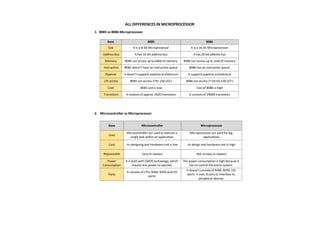
2. Microcontroller vs Microprocessor
Base Microcontroller Microprocessor
Uses
Microcontroller are used to execute a
single task within an application
Microprocessor are used for big
applications
Cost Its designing and hardware cost is low Its design and hardware cost is high
Replaceable Easy to replace Not so easy to replace
Power
Consumption
It is built with CMOS technology, which
require less power to operate.
The power consumption is high because it
has to control the entire system.
Parts
It consists of CPU, RAM, ROM and I/O
ports.
It doesn’t consists of RAM, ROM, I/O
ports. It uses its pins to interface to
peripheral devices.
2. 3. Memory Mapped I/O vs I/O Mapped I/O
Base Memory Mapped I/O I/O Mapped I/O
Basic I/O devices are treated as memory I/O devices are treated as I/O devices.
Allotted
Address Size
16-bit (A0-A15) 8-bit (A0-A7)
Data Transfer
Instruction
Same for memory and I/O devices Different for memory and I/O devices
Cycles Involved Memory read and Memory Write I/O read and I/O write
Interfacing I/O
ports
Large (around 64k) Comparatively small (around 256)
Efficiency Less Comparatively more
Data
Movement
Between registers and ports Between accumulator and ports.
Example
instruction
LDA ****H
MOV A,M
IN ****H
OUT ****H
4. CSIC vs RISC Processor
Base RISC CISC
Basic RISC is a reduced instruction set. CISC is a complex instruction set.
Instruction
The number of instructions is less as
compared to CISC.
The number of instructions is more as
compared to RISC.
Addressing
mode
The addressing modes are less. The addressing modes are more.
Instruction
format
It works in a fixed instruction format. It works in a variable instruction format.
Power
consumption
The RISC consumes low power. The CISC consumes high power.
pipeline
The RISC processors are highly
pipelined.
The CISC processors are less pipelined.
Optimization
process
It optimizes the performance by
focusing on software.
It optimizes the performance by focusing
on hardware.
RAM Requires more RAM. Requires less RAM.
3. 5. SIM instruction vs RIM instruction
Base Sim Instruction Rim Instruction
Basic SIM stands for Set Interrupt Mask. RIM stands for Read Interrupt Mask.
Job
It is responsible for
masking/unmasking of RST 7.5, RST
6.5 and RST 5.5.
It checks whether RST 7.5, RST 6.5, RST 5.5
are masked or not.
Working
Process
It resets to 0 RST 7.5 flip flop.
It checks whether interrupts are enabled or
not and whether RST 7.5, RST 6.5 or RST 5.5
interrupts are pending or not.
Accumulator
Value
The content of the Accumulator
decides the action to be taken. So
before executing the SIM instruction,
it is mandatory to initialize
Accumulator with the required value.
The contents of the Accumulator after the
execution of the RIM instruction provide this
information. Thus, it is essential to look into
the Accumulator contents after the RIM
instruction is executed.
Uses
SIM instruction can be used for serial
output of data.
RIM instruction can be used for serial input
of data.
Opcode Its opcode (in Hex) is 30. Its opcode (in Hex) is 20.
6. Software Interrupt vs Hardware Interrupt
Base Hardware Interrupt Software Interrupt
Definition
Hardware interrupt is an interrupt
generated from an external device or
hardware.
Software interrupt is the interrupt that is
generated by any internal system of the
computer.
Program
Counter
It do not increment the program
counter.
It increment the program counter.
Priority
It has lowest priority than software
interrupts
It has highest priority among all interrupts.
Event Type It is an asynchronous event. It is synchronous event.
Classification
Hardware interrupts can be classified
into two types they are: 1. Maskable
Interrupt. 2. Non-Maskable Interrupt.
Software interrupts can be classified into two
types they are: 1. Normal Interrupts. 2.
Exception
Example
Keystroke depressions and mouse
movements are examples of
hardware interrupt.
All system calls are examples of software
interrupts
4. 7. 8253 vs 8254 - Programmable Interval Timer
Base 8253 8254
Frequency Its operating frequency is 0 - 2.6 MHz Its operating frequency is 0 - 10 MHz
Technology It uses N-MOS technology It uses H-MOS technology
Read-Back
command
Read-Back command is not available Read-Back command is available
interleaved
Reads and writes of the same counter
cannot be interleaved.
Reads and writes of the same counter can be
interleaved.
8. PROM vs EPROM
Parameters PROM EPROM
Full Form Programmable Read-Only Memory. Erasable Programmable Read-Only Memory.
Reuse
It is not reusable in any way. We can
only write/feed content ONCE on a
PROM.
It is reusable. We can rewrite/erase the
content present on an EPROM easily.
Cost
Efficiency
It is more cost-efficient and
comparatively inexpensive as
compared to EPROM.
It is less cost-efficient and comparatively
costlier as compared to PROM.
Reversibility
PROM has a permanent memory
thus the process is irreversible.
We can reverse the storage process of EPROM
since the memory isn’t permanent at all.
Storage
Endurance
It has a very high storage endurance.
It has a comparatively lower storage
endurance. It is easily affected by radiation
and electrical noise.
Type
It is a read-only type of memory
storage system.
It can be both written and read optically.
Version
It is the older and outdated version
of EPROM.
It is the newer and updated version of PROM.
Scalability
and
Flexibility
It is MORE scalable and flexible. It is LESS scalable and flexible.
Constructing
Material
We use bipolar transistors in the
construction of PROM.
We use MOS transistors in the construction of
PROM.
6. [1]
TRAP & HOLD which interrupt has the highest priority and why?
TRAP has the highest priority in all interrupts.
Because, TRAP cannot be masked but it can be delayed using HOLD signal. This interrupt
transfers the microprocessor’s control to location 0024H.
Explain the need to de-multiplex the bus AD7-AD0. [1]
As AD7-AD0 lines serve a dual purpose they have to be demultiplexed to get all the information.
The address’s high order bits remain on the bus for 3 clock period.
The low order bits remain for only 1 clock period and may be lost if they are not save externally.
What is multiplexing in 8085? [2]
The data and the lower order address bus on the 8085 microprocessor are multiplexed with
each other.
Multiplexing is used to reduce the number of pins of 8085, which otherwise would have been a
48 pin chip. But because of multiplexing, external hardware is required to demultiplex the lower
byte address cum data bus.
What is Instruction register in 8085 MP? [2]
o The Instruction Register (IR) is another internal component of the 8085 microprocessor.
o It is a special register that holds the instruction currently being executed. The instruction is
fetched from memory and loaded into the IR, where it is decoded and executed.
o The IR acts as a buffer between the memory and the control unit, which interprets the
instruction and generates the necessary control signals to execute it.
o This way the IR holds the instruction and makes sure that the instruction is executed
correctly and in the correct order.
How Ready signal is used in microprocessor. [2]
o This signal is sent by an input or output device to the microprocessor.
o Ready signal indicates that the input or output device is ready to send or receive data.
o A slow input or output device is connected to the microprocessor through ready line.
When Ready is HIGH, it indicates the input/output device is ready to send/receive data When
Ready is LOW, microprocessor will wait until ‘Ready’ becomes high.
Explain how a microprocessor differentiates positive and negative number. [2]
Microprocessor normally cannot isolate positive and negative number.
It can only represent the bit pattern of given numbers. Here, the left most or most significant
bit is the sign bit. It tells the microprocessor about the sign of that number.
If the MSB is 0 then, the given number is positive and if 1 then it’s a negative number.
Discuss instruction cycle, machine cycle, and T-state. [2]
o Instruction Cycle: The time required to execute an instruction is called an instruction
cycle.
o Machine Cycle: The time required to access the memory or I/O devices is called machine
cycle.
o T-States: Instruction and Machine cycle takes multiple clock period. The portion of an
operation is carried out in one system clock period, is called as T-states.
7. Mention all the ports present in 8255 [2]
8255A has three ports, i.e. PORT A, PORT B AND PORT C.
o PORT A: Contains one 8-bit output latch/buffer and one 8-bit input buffer.
o PORT B: Similar as PORT-A.
o PORT C: Can be split in 2 parts, i.e. PORT-C lower (PC0-PC3) & PORT-C Upper (PC4-PC7)
by the control word.
What is cache controller? [2]
o Define: The cache controller is a hardware the copies code or data from main memory to
cache memory automatically.
o Uses: It performs this task automatically to concate cache operation from the software it
supports.
What Happens when RET instruction is executed? [2]
o RET Stands for ‘Return from Subroutine’.
o It is a one byte instruction.
o After the execution of this program, it transfer the control back to the main program
where it has stopped.
o It transfer program control to a return address located on the top of the stack. The
address is manually placed on the stack by a CALL instruction.
o The return address is popped from the top of the stack into the program counter.
What are HOLD and HLDA? [2]
o When another device of the computer system requires address and data buses for fata
transfer. It sends HOLD signal to the microprocessor.
o After receiving the HOLD request, the microprocessor sends out a HLDA (HOLD
Acknowledgment) signal to the device.
How are they used? [2]
o When microprocessor receive ‘HOLD’ signal it leaves the control over the buses as soon
as the current machine cycle is completed, internal processing may continue.
o After the removal of HOLD signal, the HLDA goes low and thereafter the microprocessor
takes the control back over the buses.
How address bus and data bus are separated in 8085 MP. [4]
In the 8085 microprocessor, the address bus and data bus are physically separated and serve
different functions.
The address bus is used to transmit the memory address of the location where the data
is to be stored or retrieved. It is a 16-bit bus, allowing the 8085 to address up to 64KB of
memory.
The data bus, on the other hand, is used to transmit the actual data between the
microprocessor and memory or input/output devices. It is an 8-bit bus, allowing the
8085 to process 8-bit data at a time.
The internal components of the 8085 microprocessor such as ALU, IR and registers are
connected to both address and data bus. The separation of the address bus and data bus
allows for efficient communication between the microprocessor and memory or
input/output devices, and enables the microprocessor to process both memory addresses
and data simultaneously.
8. Instructions and their required Machine Cycles in 8085
Give the bit configuration of 8085 flag register. [4]
1. A flag is a single bit status register (Flip-Flop).
2. Flags are either set or reset by ALU according to the result by ALU.
3. Flags are important because they are the conditions for conditional branching instructions.
4. 8085 has five flags. Sign flag, Zero flag, Auxiliary Carry flag, Parity flag and Carry flag. An 8-bit
register is used to represent five flags as shown in the following figure
Explain the working procedure of DCR and DAD with examples. [4]
The working procedure of DCR (Decrement Register) and DAD (Double Add) instruction in the 8085
Microprocessor is as follows:
o DCR (Decrement Register):
It is a 1-byte instruction that decrements the contents of a specified register or memory
location by 1.
The instruction format is "DCR R" where R can be any register from B, C, D, E, H, or L.
For example, "DCR B" will decrement the contents of register B by 1.
The operation performed by DCR is similar to the following expression: R = R - 1
o DAD (Double Add):
It is a 2-byte instruction that adds the contents of two specified register pairs (B and D, or
H and L) and stores the result in the H register.
The instruction format is "DAD H" or "DAD B".
For example, "DAD H" will add the contents of register pair H-L and store the result in H.
The operation performed by DAD is similar to the following expression: H = H + L + carry.
The carry flag is updated based on the result of the addition.
S.No Instruction No. of MC’S MC-1 MC-2 MC-3 MC-4
1 MOV A,B 1 OF - - -
2 MVI A,06H 2 OF MR - -
3 LXI H,4050H 3 OF MR MR -
4 INR M 3 OF MR MW -
5 LDA 5000H 4 OF MR MR MR
6 STA 3050H 4 OF MR MR MW
7 IN 80H 3 OF MR IOR -
8 OUT 80h 3 OF MR IOW -
9. NOP instruction and its utility. [4]
o NOP (No Operation) Instruction:
NOP is a 1-byte instruction in the 8085 Microprocessor that does not perform any
operation.
The instruction format is simply "NOP".
When the 8085 fetches and executes a NOP instruction, it simply increments the program
counter and fetches the next instruction.
NOP does not affect the contents of any register or memory location.
o Utility of NOP Instruction:
NOP is often used as a placeholder or dummy instruction in the program.
It can be used to fill the unused space in the program, where the programmer may want to
insert some instructions later.
NOP can be used to insert a delay in the program. For example, when waiting for a slower
device to complete an operation, NOP instructions can be used to fill the time.
NOP can also be used to align the code in certain systems where instructions must start at
specific addresses.
In conclusion, NOP is a dummy instruction that does not perform any operation. It is used in various
ways, such as a placeholder, to insert delays, align code, or measure system performance.
Interrupts in 8085 [4/5]
Interrupts are the signals generated by the external devices to request the microprocessor to
perform a task. There are 5 interrupt signals, i.e. TRAP, RST 7.5, RST 6.5, RST 5.5, and INTR.Interrupt
are classified into following groups based on their parameter −
o Vector interrupt − In this type of interrupt, the interrupt address is known to the processor.
For example: RST7.5, RST6.5, RST5.5, TRAP.
o Non-Vector interrupt − In this type of interrupt, the interrupt address is not known to the
processor so, the interrupt address needs to be sent externally by the device to perform
interrupts. For example: INTR.
o Maskable interrupt − In this type of interrupt, we can disable the interrupt by writing some
instructions into the program. For example: RST7.5, RST6.5, RST5.5.
o Non-Maskable interrupt − In this type of interrupt, we cannot disable the interrupt by
writing some instructions into the program. For example: TRAP.
o Software interrupt − In this type of interrupt, the programmer has to add the instructions
into the program to execute the interrupt. There are 8 software interrupts in 8085, i.e. RST0,
RST1, RST2, RST3, RST4, RST5, RST6, and RST7.
o Hardware interrupt − There are 5 interrupt pins in 8085 used as hardware interrupts, i.e.
TRAP, RST7.5, RST6.5, RST5.5, INTA.