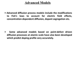
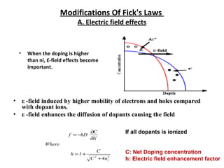
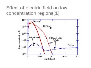
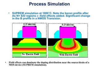
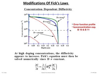
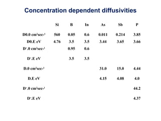
Microelectronics Technology
Dopant Diffusion III
Advanced Models
• Advanced diffusion process models include the modifications
to Fick’s laws to account for electric field effects,
concentration-dependent diffusion, dopant segregation etc.
• Some advanced models based on point-defect driven
diffusion processes at atomic scale have also been developed
which predict doping profile very accurately.
Modifications Of Fick's Laws
A. Electric field effects
• When the doping is higher
than ni, £-field effects become
important.
• ε -field induced by higher mobility of electrons and holes compared
with dopant ions.
• ε -field enhances the diffusion of dopants causing the field
2
4 i
2
nC
C
1h
Where
X
C
hDf
+
+=
∂
∂
−=
If all dopants is ionized
C: Net Doping concentration
h: Electric field enhancement factor
Process Simulation
• SUPREM simulation at 1000˚C. Note the boron profile after
As N+ S/D regions e -field effects added. Significant change
in the B profile in a NMOS Transistor.
• Field effects can dominate the doping distribution near the source/drain of a
MOS device (SUPREM simulation).
Dr. G. Eranna Integrated Circuit Fabrication Technology © CEERI Pilani
Modifications Of Fick's Laws
• Error function profile
• Isoconcentration exp.
B 10 & B 11
Si B In As Sb P
D0.0 cm2
sec-1
560 0.05 0.6 0.011 0.214 3.85
D0.E eV 4.76 3.5 3.5 3.44 3.65 3.66
D+
.0 cm2
sec-1
0.95 0.6
D+
.E eV 3.5 3.5
D.0 cm2
sec-1
31.0 15.0 4.44
D.E eV 4.15 4.08 4.0
D=
.0 cm2
sec-1
44.2
D=
.E eV 4.37
Concentration dependent diffusivities
Segregation
TSUPREM IV Plot of B contours after oxidation of uniformly B-doped substrate
• Dopants have different solubilities in different material: Redistribute
until chemical potential is same on both sides of the interface.
• Segregation Coefficient: Ratio of equilibrium doping conc.on
each side of interface
K0=Csi/CSiO2
K0= 0.3 (B)
K0=10
(As,Sb,P)
Dr. G. Eranna Integrated Circuit Fabrication Technology © CEERI Pilani
Segregation
Interfacial Dopant Pile-up
• Dopants may also pile up at the interface layer, perhaps only a
monolayer thick. Interfacial dopant dose loss or pile-up may
consume up to 50% of the dose in a shallow layer.
• In the experiment (right) 40% of the dose was lost in a 30
sec anneal.
Summary of Macroscopic Approach to
Diffusion
• Fick's first law correctly describes dopant diffusion
in the limit of low concentrations.
• "Fixes" to this law to account for experimental
observations (concentration dependent diffusion
and e -field effects), are useful, but at this point the
complexity of the "fixes" begins to outweigh their
usefulness.
We turn to an atomistic view of diffusion for a
deeper understanding.
Kick-out and Interstitial(cy) Assisted
Mechanisms.
Mathematically it is identical to the kick out process
and both are referred to as interstitial assisted
diffusion
Inferences About Mechanisms
• Oxidation provides an I injection source.
• Nitridation provides a V injection source.
• Stacking faults serve as "detectors" as do dopant which
diffuse.
• Roles of both I &V in assisting dopant diffusion in Si
Atomic Scale Interactions
• Consider the simple Dopant-Defect Interactions
A + I <----> AI
• For example OED is explained because oxidation injects I driving the
equation to the right, creating more AI pairs and enhancing the dopant D.
• Even under inert conditions, atomic-level description says that dopant
diffusion from the surface contains lot of AI,driving above Eq. to left thus
pumping interstitials (Chemical Pumping)
• In the more complex example below, phosphorus diffuses with I, and
releases them in the bulk. This enhances the tail region D.
Dr. G. Eranna Integrated Circuit Fabrication Technology © CEERI Pilani
Emitter Push Effect
Pumping of interstitials by diffusion of P which builds up a high
supersaturation of these point defects in the interior of sample
Summary of Key Ideas
• Selective doping is a key process in fabricating semiconductor
devices.
• Doping atoms generally must sit on substitutional sites to be
electrically active.
• Both doping concentration and profile shape are critical in
device electrical characteristics.
• Ion implantation is the dominant process used to introduce
dopant atoms. This creates damage and thermal annealing is
required to repair this damage.
• Powerful simulation tools exist today which model diffusion
processes and can predict complex doping profiles.
7.2. dopant diffusion 3,2013 microtech

7.2. dopant diffusion 3,2013 microtech

  • 1.
  • 2.
    Advanced Models • Advanceddiffusion process models include the modifications to Fick’s laws to account for electric field effects, concentration-dependent diffusion, dopant segregation etc. • Some advanced models based on point-defect driven diffusion processes at atomic scale have also been developed which predict doping profile very accurately.
  • 3.
    Modifications Of Fick'sLaws A. Electric field effects • When the doping is higher than ni, £-field effects become important. • ε -field induced by higher mobility of electrons and holes compared with dopant ions. • ε -field enhances the diffusion of dopants causing the field 2 4 i 2 nC C 1h Where X C hDf + += ∂ ∂ −= If all dopants is ionized C: Net Doping concentration h: Electric field enhancement factor
  • 5.
    Process Simulation • SUPREMsimulation at 1000˚C. Note the boron profile after As N+ S/D regions e -field effects added. Significant change in the B profile in a NMOS Transistor. • Field effects can dominate the doping distribution near the source/drain of a MOS device (SUPREM simulation).
  • 6.
    Dr. G. ErannaIntegrated Circuit Fabrication Technology © CEERI Pilani Modifications Of Fick's Laws • Error function profile • Isoconcentration exp. B 10 & B 11
  • 7.
    Si B InAs Sb P D0.0 cm2 sec-1 560 0.05 0.6 0.011 0.214 3.85 D0.E eV 4.76 3.5 3.5 3.44 3.65 3.66 D+ .0 cm2 sec-1 0.95 0.6 D+ .E eV 3.5 3.5 D.0 cm2 sec-1 31.0 15.0 4.44 D.E eV 4.15 4.08 4.0 D= .0 cm2 sec-1 44.2 D= .E eV 4.37 Concentration dependent diffusivities
  • 8.
    Segregation TSUPREM IV Plotof B contours after oxidation of uniformly B-doped substrate • Dopants have different solubilities in different material: Redistribute until chemical potential is same on both sides of the interface. • Segregation Coefficient: Ratio of equilibrium doping conc.on each side of interface K0=Csi/CSiO2 K0= 0.3 (B) K0=10 (As,Sb,P)
  • 9.
    Dr. G. ErannaIntegrated Circuit Fabrication Technology © CEERI Pilani Segregation
  • 10.
    Interfacial Dopant Pile-up •Dopants may also pile up at the interface layer, perhaps only a monolayer thick. Interfacial dopant dose loss or pile-up may consume up to 50% of the dose in a shallow layer. • In the experiment (right) 40% of the dose was lost in a 30 sec anneal.
  • 11.
    Summary of MacroscopicApproach to Diffusion • Fick's first law correctly describes dopant diffusion in the limit of low concentrations. • "Fixes" to this law to account for experimental observations (concentration dependent diffusion and e -field effects), are useful, but at this point the complexity of the "fixes" begins to outweigh their usefulness. We turn to an atomistic view of diffusion for a deeper understanding.
  • 13.
    Kick-out and Interstitial(cy)Assisted Mechanisms. Mathematically it is identical to the kick out process and both are referred to as interstitial assisted diffusion
  • 15.
    Inferences About Mechanisms •Oxidation provides an I injection source. • Nitridation provides a V injection source. • Stacking faults serve as "detectors" as do dopant which diffuse. • Roles of both I &V in assisting dopant diffusion in Si
  • 17.
    Atomic Scale Interactions •Consider the simple Dopant-Defect Interactions A + I <----> AI • For example OED is explained because oxidation injects I driving the equation to the right, creating more AI pairs and enhancing the dopant D. • Even under inert conditions, atomic-level description says that dopant diffusion from the surface contains lot of AI,driving above Eq. to left thus pumping interstitials (Chemical Pumping) • In the more complex example below, phosphorus diffuses with I, and releases them in the bulk. This enhances the tail region D.
  • 18.
    Dr. G. ErannaIntegrated Circuit Fabrication Technology © CEERI Pilani Emitter Push Effect Pumping of interstitials by diffusion of P which builds up a high supersaturation of these point defects in the interior of sample
  • 19.
    Summary of KeyIdeas • Selective doping is a key process in fabricating semiconductor devices. • Doping atoms generally must sit on substitutional sites to be electrically active. • Both doping concentration and profile shape are critical in device electrical characteristics. • Ion implantation is the dominant process used to introduce dopant atoms. This creates damage and thermal annealing is required to repair this damage. • Powerful simulation tools exist today which model diffusion processes and can predict complex doping profiles.