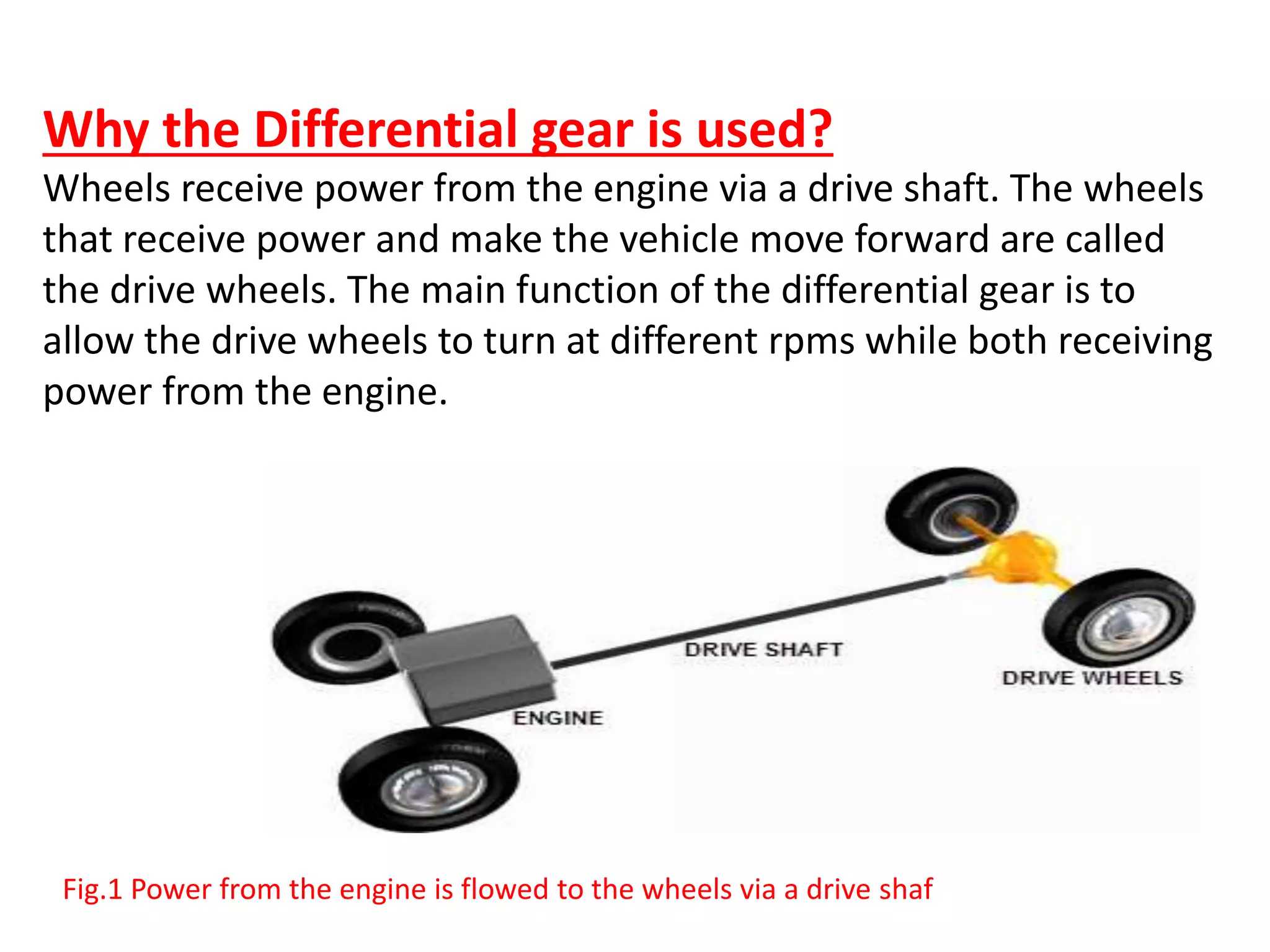
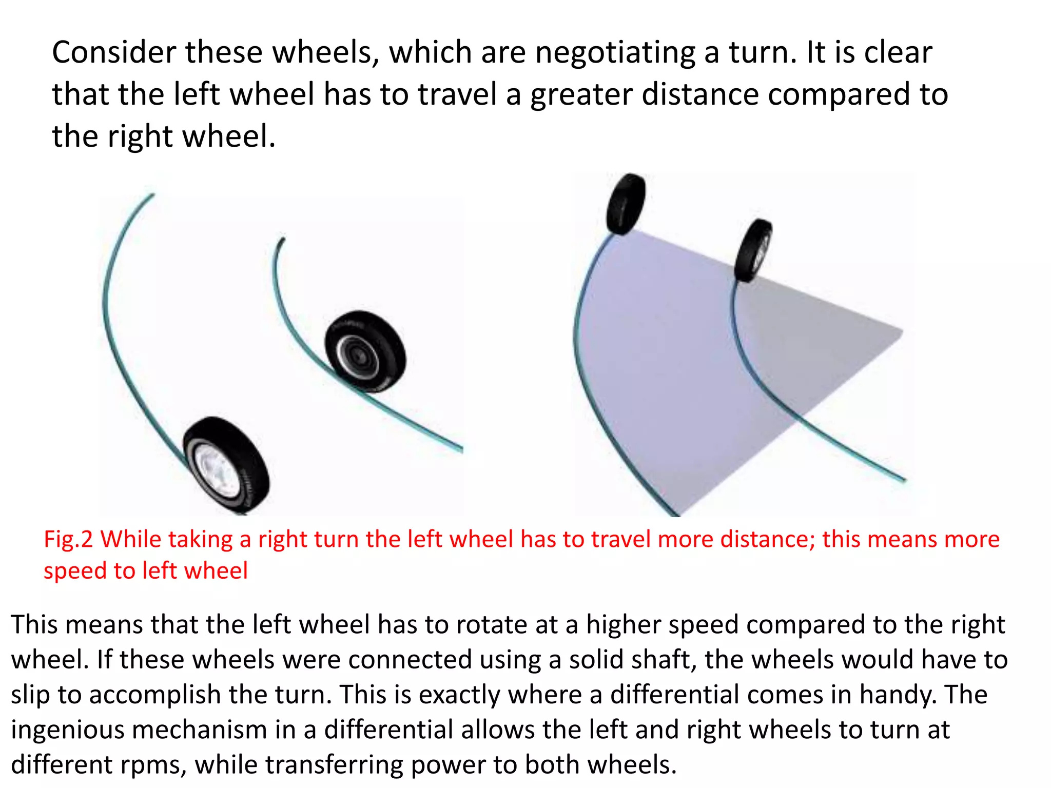
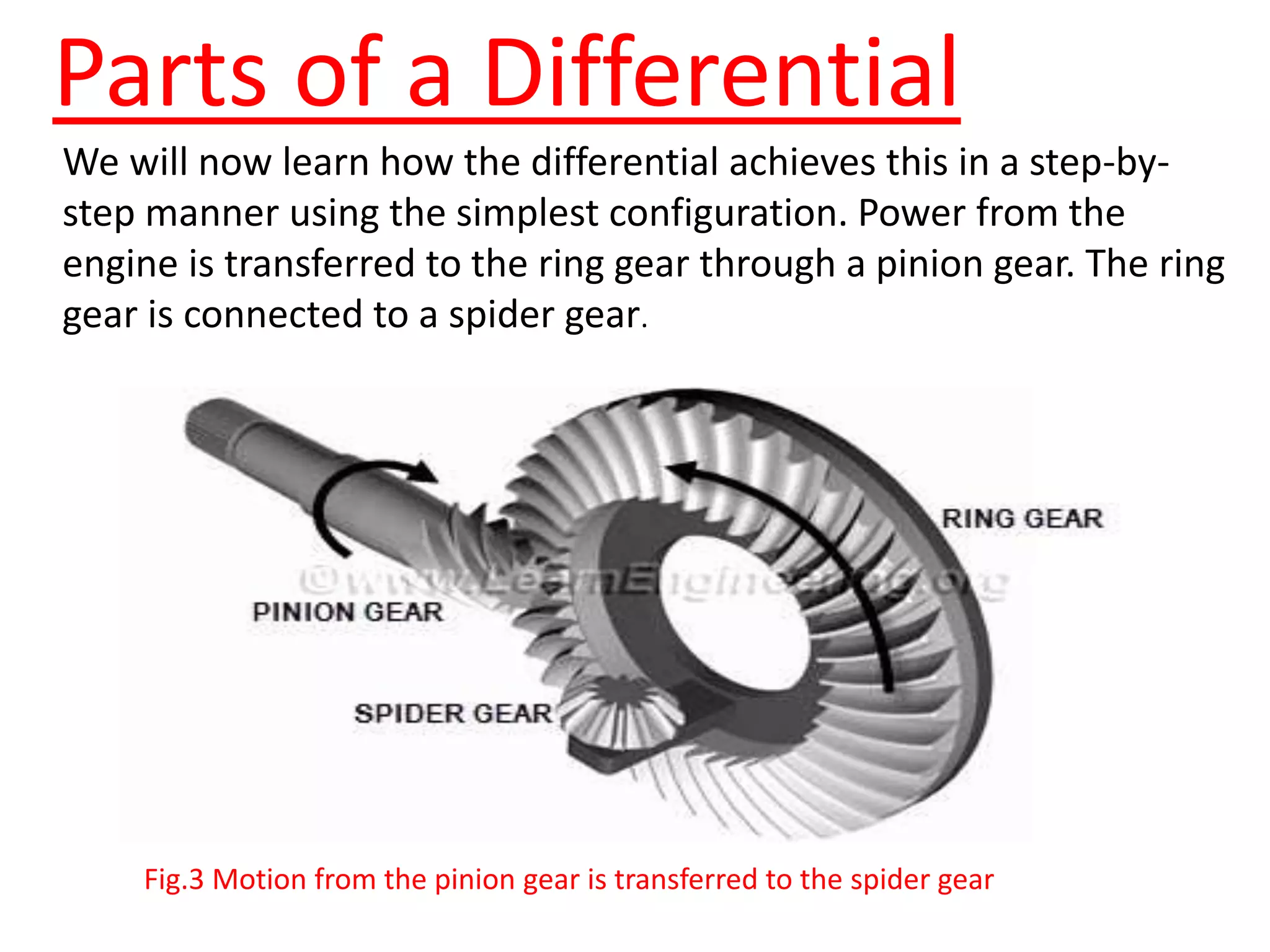
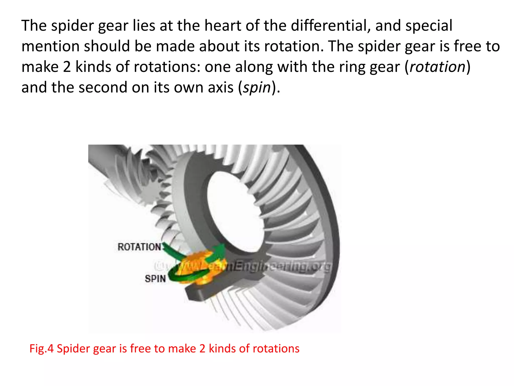
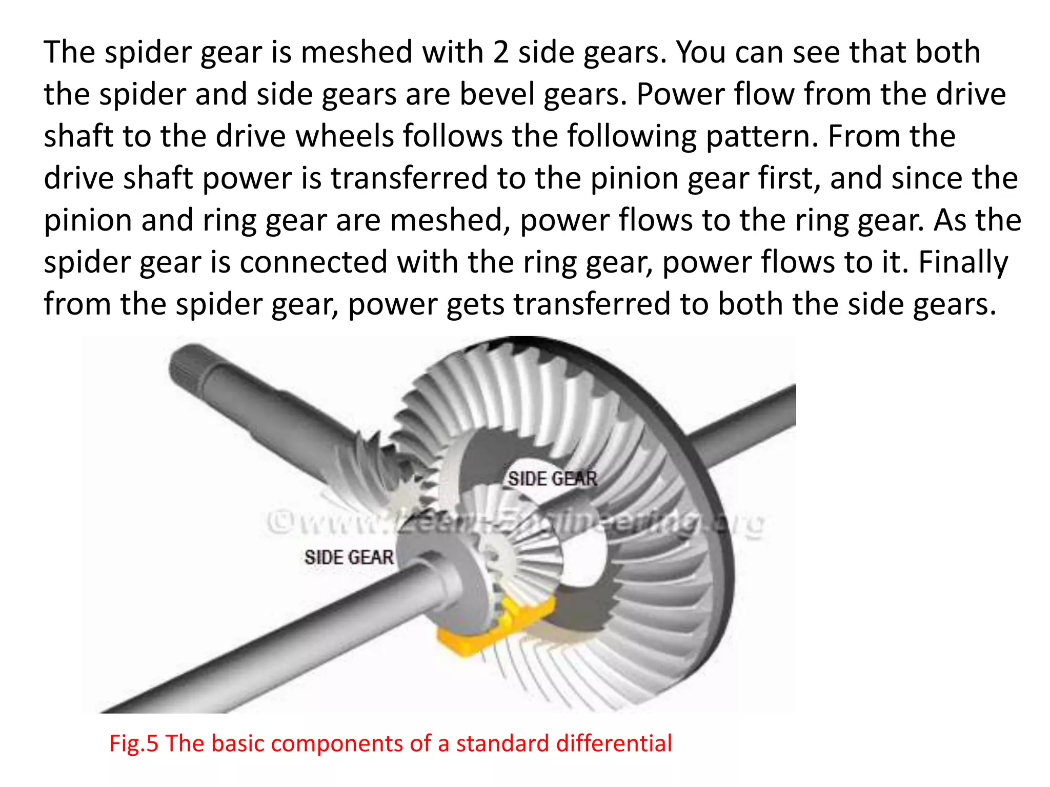
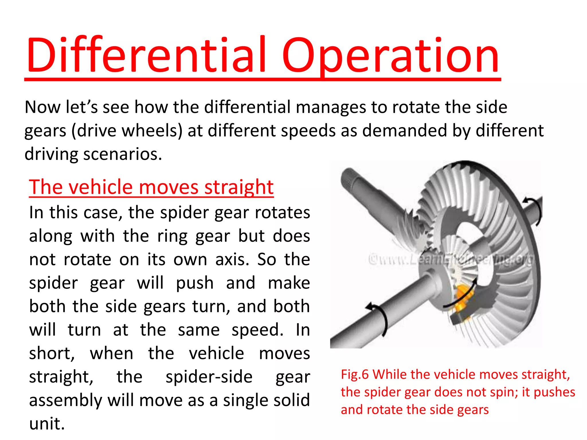
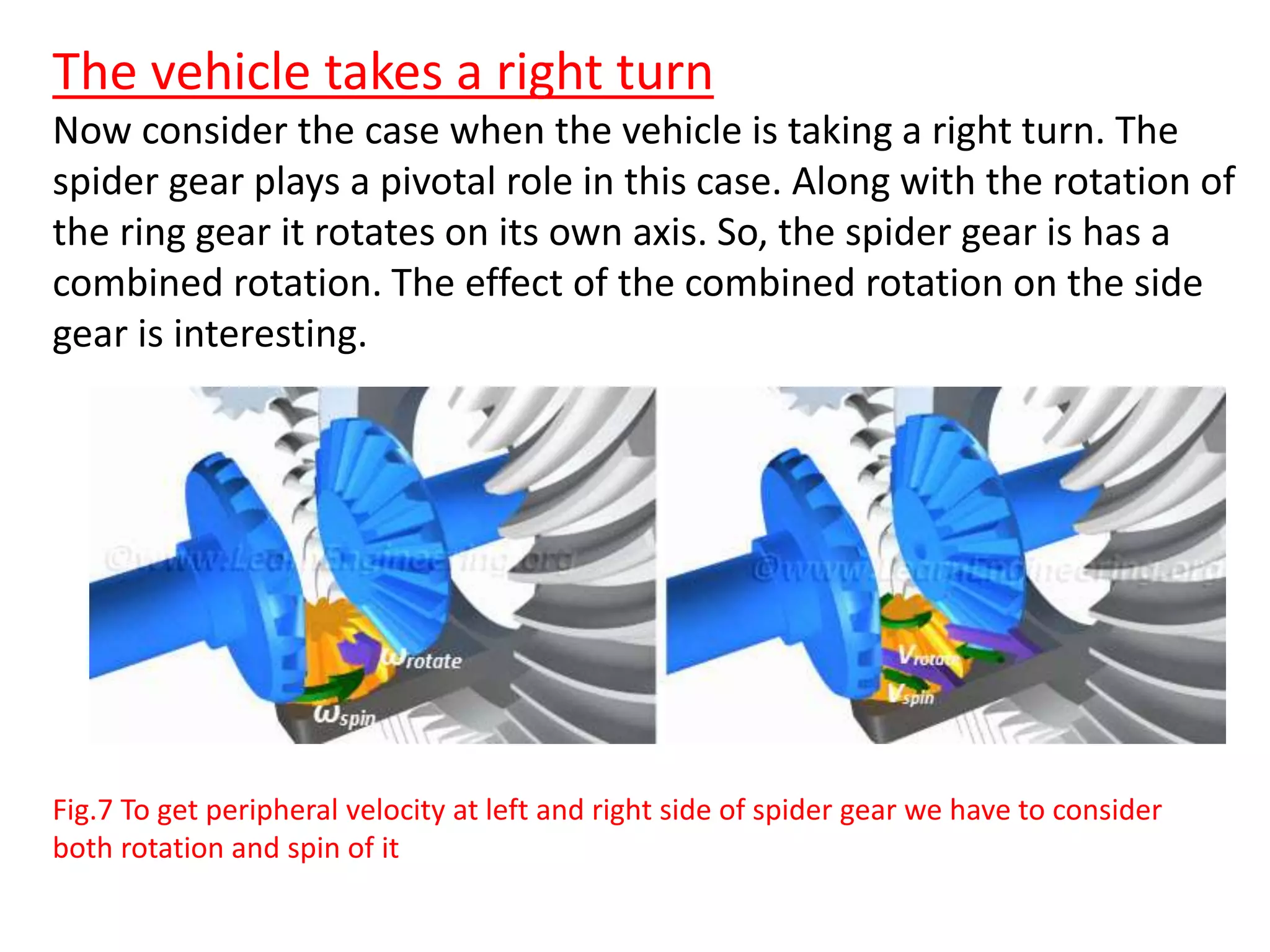
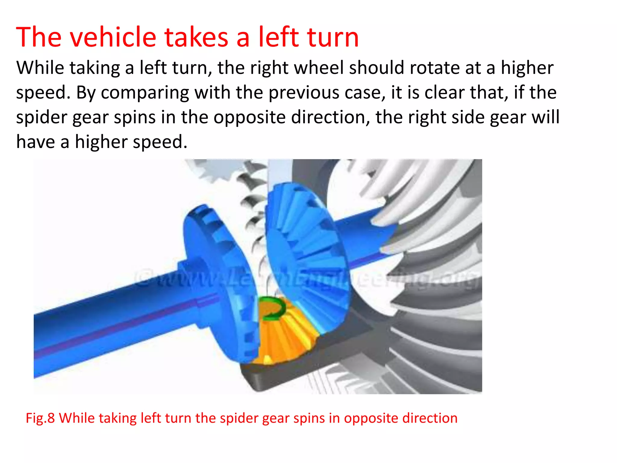
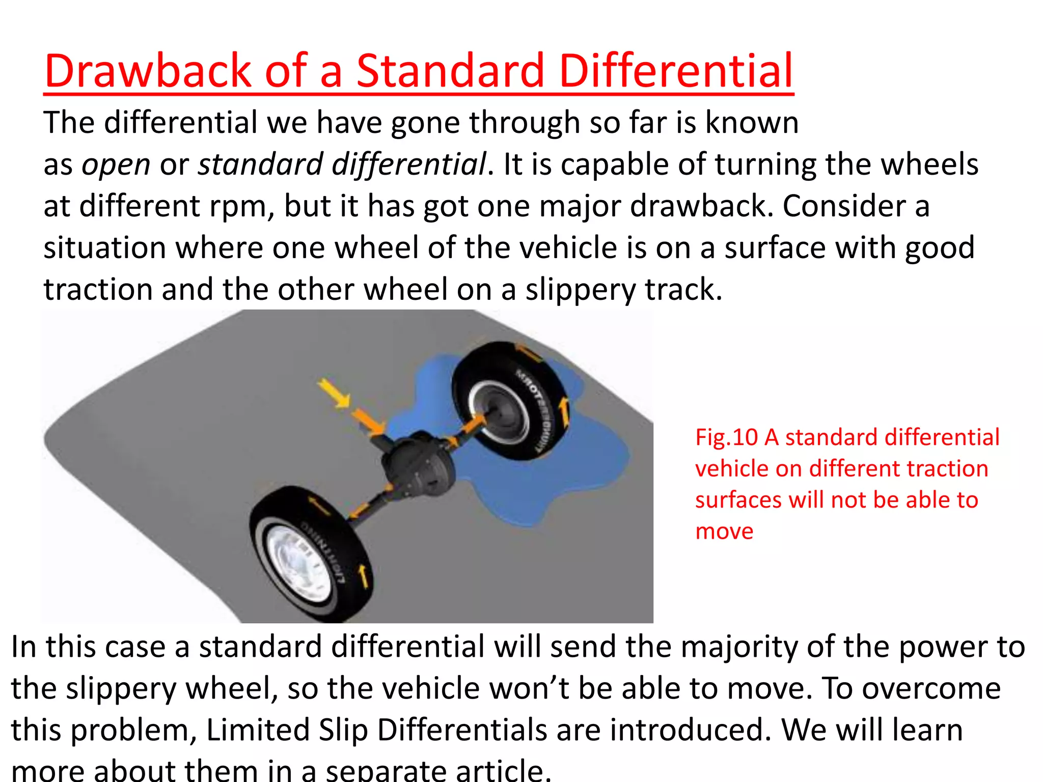
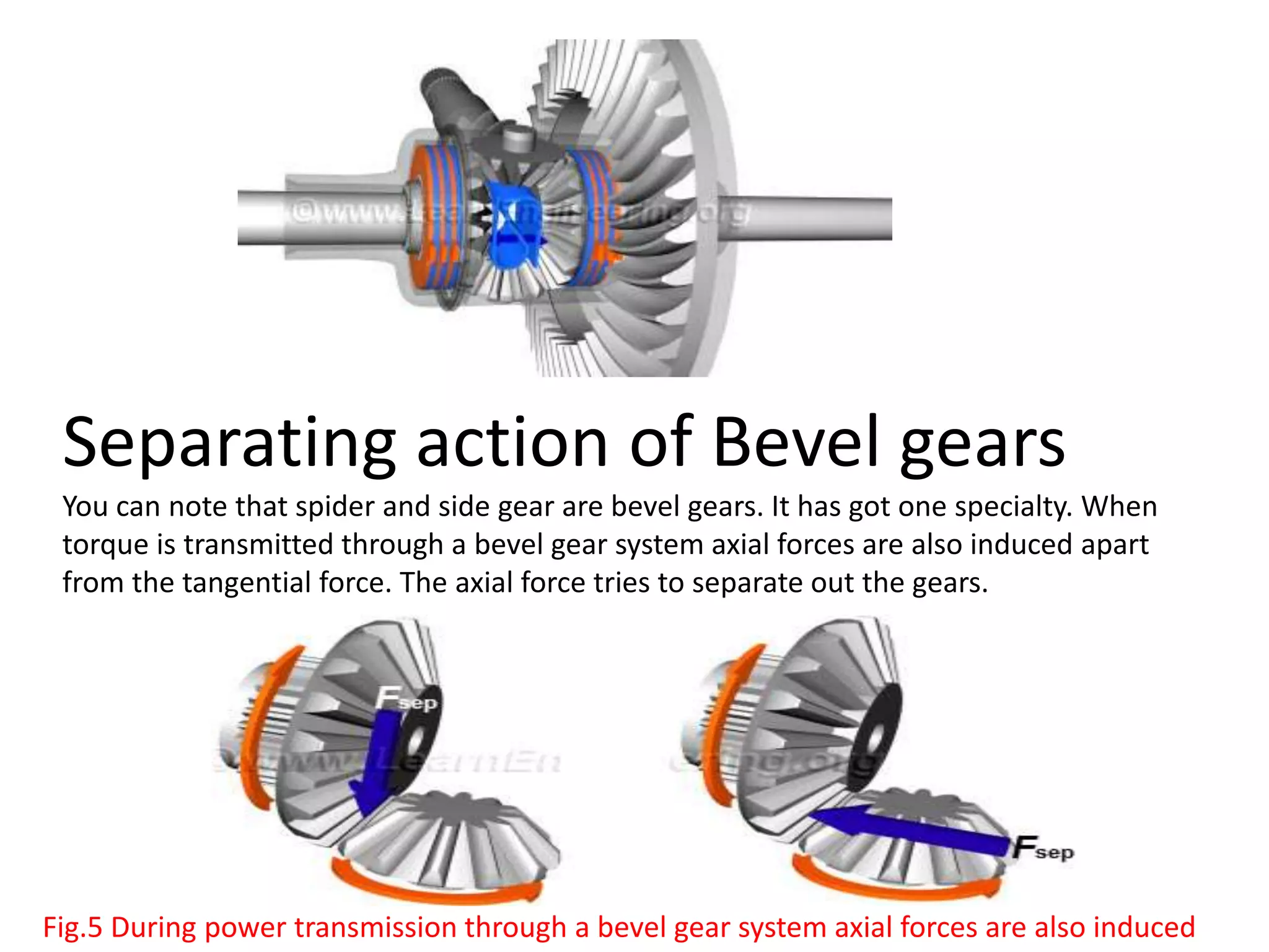
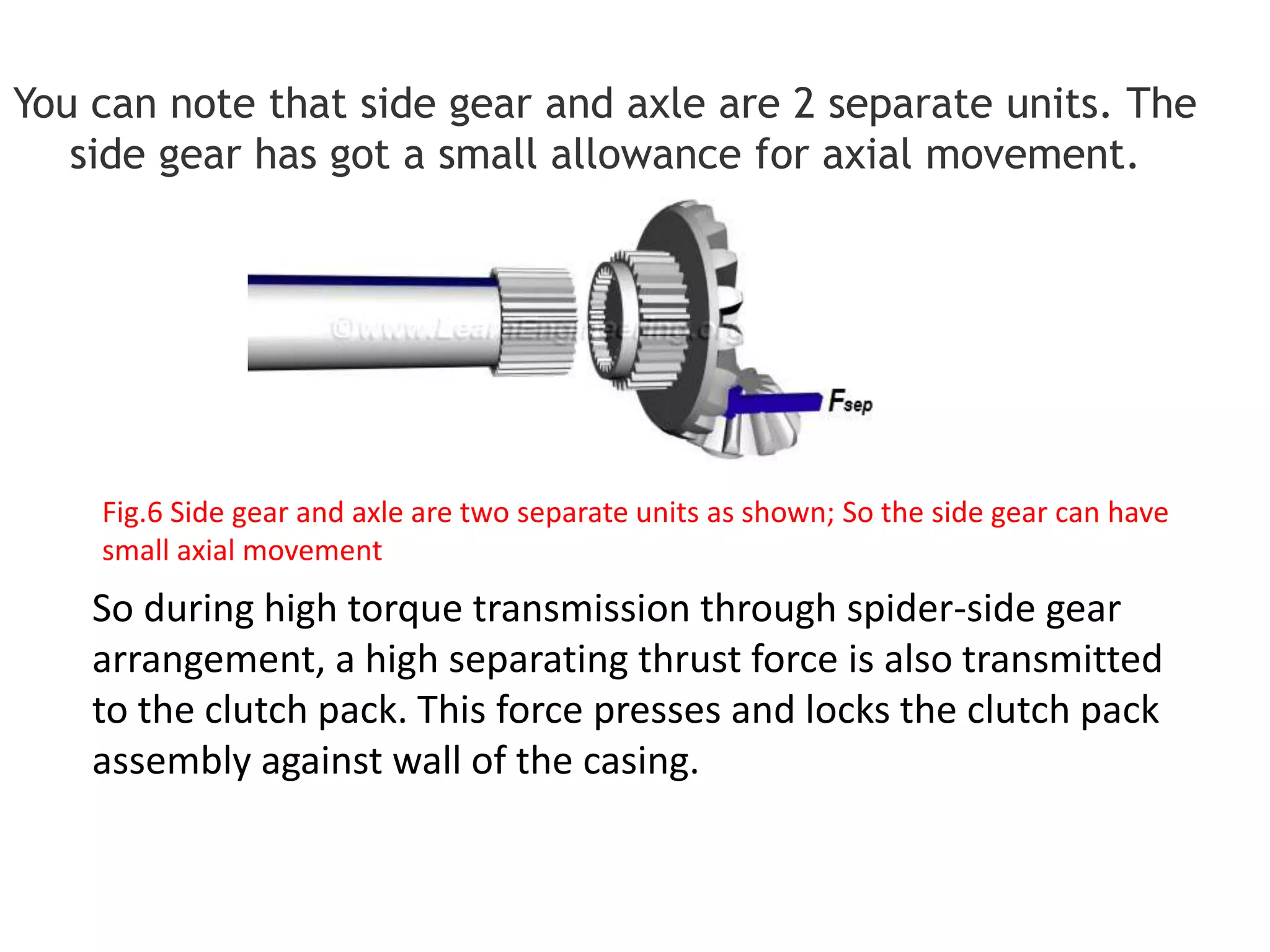
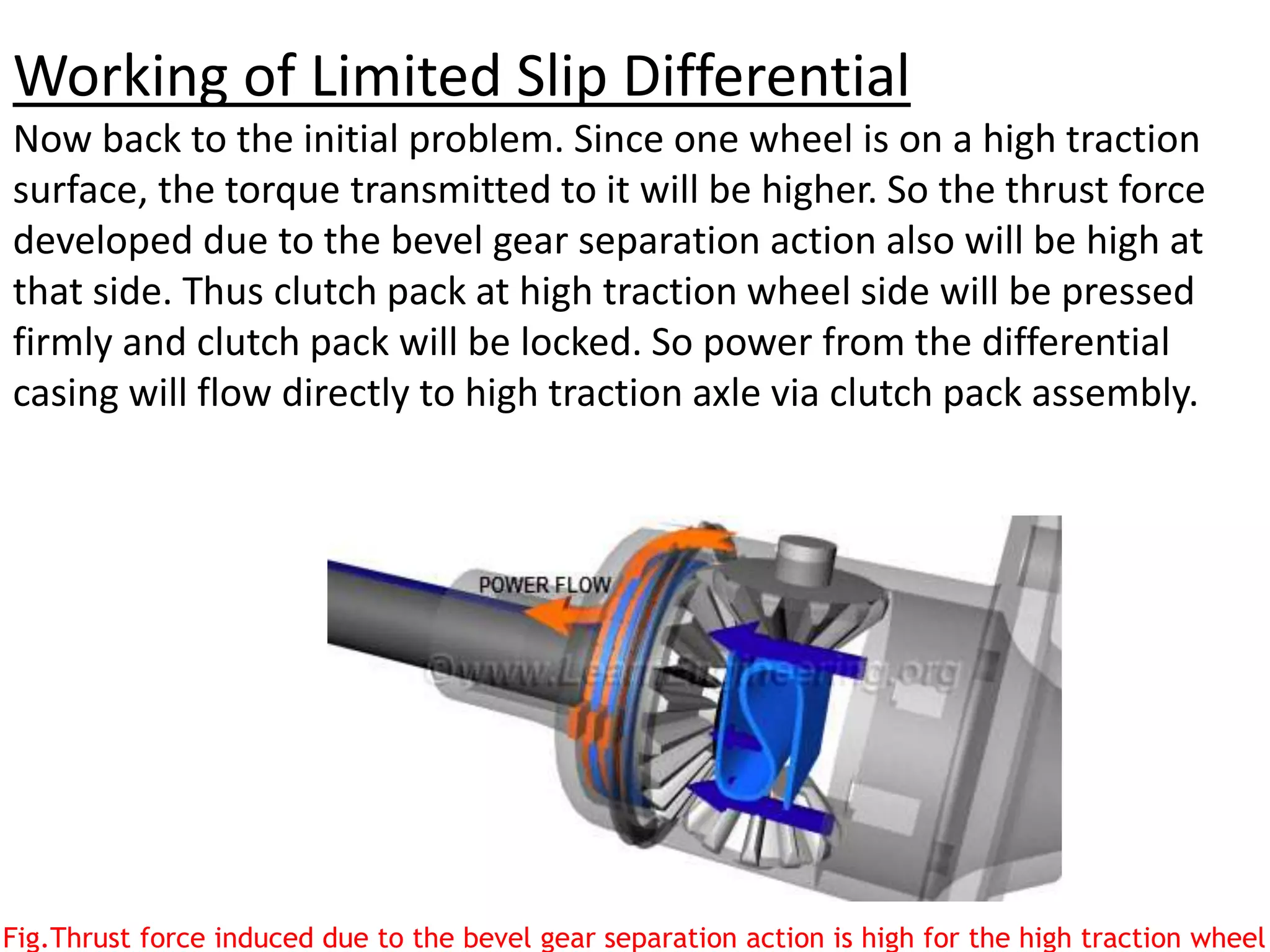
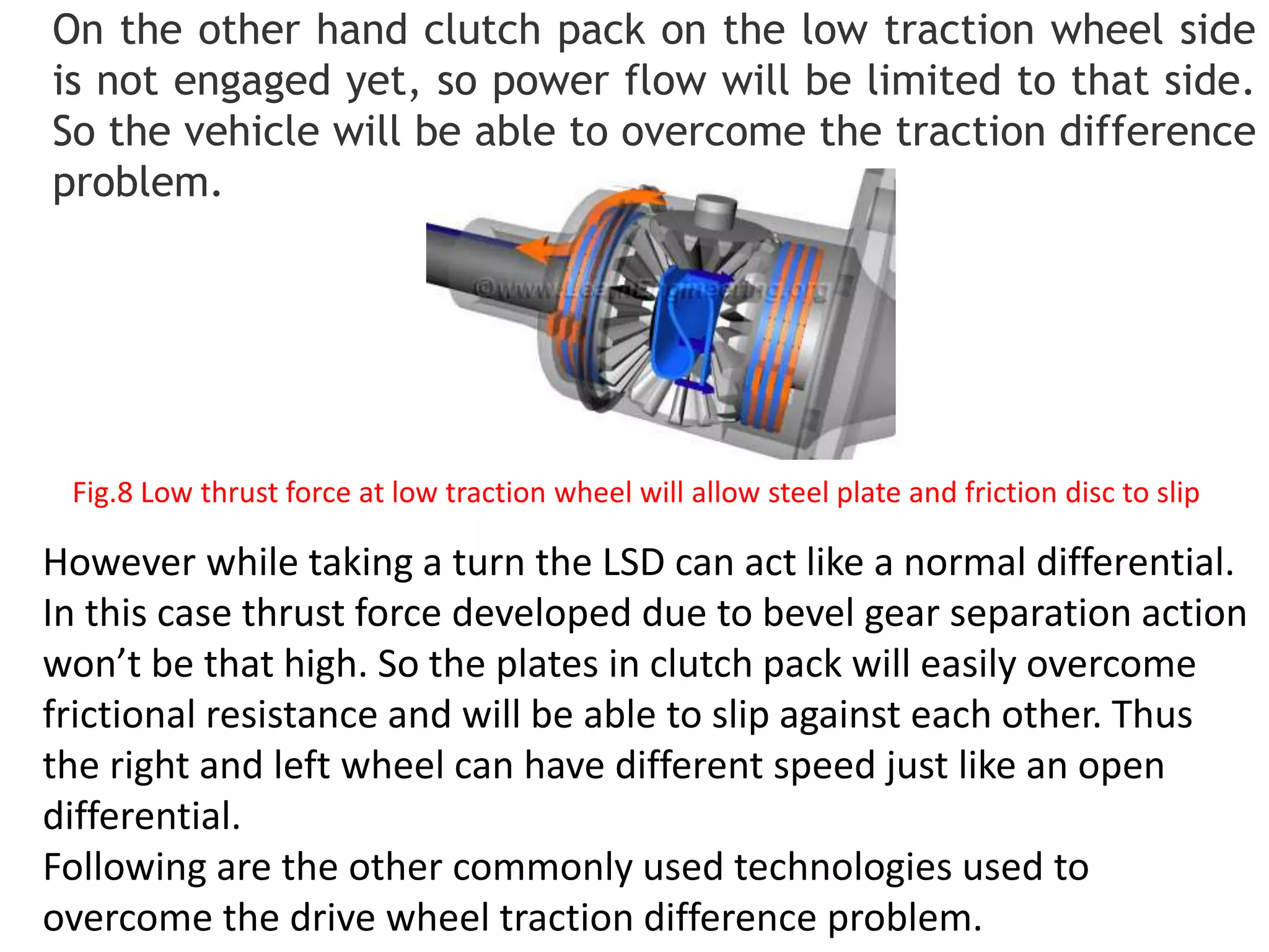
DIFFERENTIAL SYSTEM
ABHISHEK KUMAR GUPTA
HCST
Why the Differential gear is used?
Wheels receive power from the engine via a drive shaft. The wheels
that receive power and make the vehicle move forward are called
the drive wheels. The main function of the differential gear is to
allow the drive wheels to turn at different rpms while both receiving
power from the engine.
Fig.1 Power from the engine is flowed to the wheels via a drive shaf
Consider these wheels, which are negotiating a turn. It is clear
that the left wheel has to travel a greater distance compared to
the right wheel.
Fig.2 While taking a right turn the left wheel has to travel more distance; this means more
speed to left wheel
This means that the left wheel has to rotate at a higher speed compared to the right
wheel. If these wheels were connected using a solid shaft, the wheels would have to
slip to accomplish the turn. This is exactly where a differential comes in handy. The
ingenious mechanism in a differential allows the left and right wheels to turn at
different rpms, while transferring power to both wheels.
Parts of a Differential
We will now learn how the differential achieves this in a step-by-
step manner using the simplest configuration. Power from the
engine is transferred to the ring gear through a pinion gear. The ring
gear is connected to a spider gear.
Fig.3 Motion from the pinion gear is transferred to the spider gear
The spider gear lies at the heart of the differential, and special
mention should be made about its rotation. The spider gear is free to
make 2 kinds of rotations: one along with the ring gear (rotation)
and the second on its own axis (spin).
Fig.4 Spider gear is free to make 2 kinds of rotations
The spider gear is meshed with 2 side gears. You can see that both
the spider and side gears are bevel gears. Power flow from the drive
shaft to the drive wheels follows the following pattern. From the
drive shaft power is transferred to the pinion gear first, and since the
pinion and ring gear are meshed, power flows to the ring gear. As the
spider gear is connected with the ring gear, power flows to it. Finally
from the spider gear, power gets transferred to both the side gears.
Fig.5 The basic components of a standard differential
Differential Operation
Now let’s see how the differential manages to rotate the side
gears (drive wheels) at different speeds as demanded by different
driving scenarios.
The vehicle moves straight
In this case, the spider gear rotates
along with the ring gear but does
not rotate on its own axis. So the
spider gear will push and make
both the side gears turn, and both
will turn at the same speed. In
short, when the vehicle moves
straight, the spider-side gear
assembly will move as a single solid
unit.
Fig.6 While the vehicle moves straight,
the spider gear does not spin; it pushes
and rotate the side gears
The vehicle takes a right turn
Now consider the case when the vehicle is taking a right turn. The
spider gear plays a pivotal role in this case. Along with the rotation of
the ring gear it rotates on its own axis. So, the spider gear is has a
combined rotation. The effect of the combined rotation on the side
gear is interesting.
Fig.7 To get peripheral velocity at left and right side of spider gear we have to consider
both rotation and spin of it
When properly meshed, the side gear has to have the same peripheral
velocity as the spider gear. Technically speaking, both gears should
have the same pitch line velocity. When the spider gear is spinning as
well as rotating, peripheral velocity on the left side of spider gear is
the sum of the spinning and rotational velocities. But on the right side,
it is the difference of the two, since the spin velocity is in the opposite
direction on this side. This fact is clearly depicted in Fig.7. This means
the left side gear will have higher speed compared to the right side
gear. This is the way the differential manages to turn left and right
wheels at different speeds.
The vehicle takes a left turn
While taking a left turn, the right wheel should rotate at a higher
speed. By comparing with the previous case, it is clear that, if the
spider gear spins in the opposite direction, the right side gear will
have a higher speed.
Fig.8 While taking left turn the spider gear spins in opposite direction
Other functions of the Differential
Apart from allowing the wheels to rotate at different rpm differential
has 2 more functions. First is speed reduction at the pinion-ring gear
assembly. This is achieved by using a ring gear which is having almost
4 to 5 times number of teeth as that of the pinion gear. Such huge
gear ratio will bring down the speed of the ring gear in the same
ratio. Since the power flow at the pinion and ring gear are the same,
such a speed reduction will result in a high torque multiplication.
You can also note one specialty of the ring gear, they are hypoid
gears. The hypoid gears have more contact area compared to the
other gear pairs and will make sure that the gear operation is
smooth.
The other function of the differential is to turn the power flow
direction by 90 degree.
Drawback of a Standard Differential
The differential we have gone through so far is known
as open or standard differential. It is capable of turning the wheels
at different rpm, but it has got one major drawback. Consider a
situation where one wheel of the vehicle is on a surface with good
traction and the other wheel on a slippery track.
In this case a standard differential will send the majority of the power to
the slippery wheel, so the vehicle won’t be able to move. To overcome
this problem, Limited Slip Differentials are introduced. We will learn
Fig.10 A standard differential
vehicle on different traction
surfaces will not be able to
move
Working of a Limited Slip Differential(LSD)
Problem with the Standard Differential
Consider a situation where a vehicle fitted with a standard
differential moves straight, and one drive wheel is on a surface
with good traction and the other wheel is on a slippery track. In
a standard differential the left and right axle rotations are
completely independent. Since one wheel is on a slippery track,
the standard differential will make that wheel spin in excessive
speed, while the good traction wheel will remain almost dead.
This means high power supply to the slippery wheel and low
power flow to the good traction wheel. So the vehicle won’t be
able to move.
Limited slip differentials (LSD) are used in automobile to overcome
the traction difference problem of drive wheels. In this article
working of LSD is explained in a logical manner.
One way to overcome this problem is to limit the independency
or relative motion between the left and right axles.Limited slip
differentials are introduced for this purpose. One of the most
commonly used LSD technology is clutch-pack based.
Fig.1 In a standard differential power from the engine is transferred to the wheel with low
traction
Constructional Features of LSD
First we will go through constructional features of LSD.
The basic components of a standard differential are shown below. It
has got pinion gear, ring gear, case, spider gears and side gears.
Apart from its basic components a Limited slip differential has got a series of
friction and steel plates packed between the side gear and the casing. Friction
discs are having internal teeth and they are locked with the splines of the side
gear. So the friction discs and the side gear will always move together.
Steels plates are having external tabs and are made to fit in the case groove. So they
can rotate with the case.
If any of the clutch pack assembly is well pressed, the frictional force within them
will make it move as a single solid unit. Since steel plates are locked with the case
and friction discs with the side gear, in a well pressed clutch pack casing and the
clutch pack will move together. Or motion from the casing is directly passed to the
corresponding axle.
Space between the side gears is fitted with a pre-load spring. Pre load spring will
always give a thrust force and will press clutch pack together.
Separating action of Bevel gears
You can note that spider and side gear are bevel gears. It has got one specialty. When
torque is transmitted through a bevel gear system axial forces are also induced apart
from the tangential force. The axial force tries to separate out the gears.
Fig.5 During power transmission through a bevel gear system axial forces are also induced
You can note that side gear and axle are 2 separate units. The
side gear has got a small allowance for axial movement.
So during high torque transmission through spider-side gear
arrangement, a high separating thrust force is also transmitted
to the clutch pack. This force presses and locks the clutch pack
assembly against wall of the casing.
Fig.6 Side gear and axle are two separate units as shown; So the side gear can have
small axial movement
Working of Limited Slip Differential
Now back to the initial problem. Since one wheel is on a high traction
surface, the torque transmitted to it will be higher. So the thrust force
developed due to the bevel gear separation action also will be high at
that side. Thus clutch pack at high traction wheel side will be pressed
firmly and clutch pack will be locked. So power from the differential
casing will flow directly to high traction axle via clutch pack assembly.
Fig.Thrust force induced due to the bevel gear separation action is high for the high traction wheel
On the other hand clutch pack on the low traction wheel side
is not engaged yet, so power flow will be limited to that side.
So the vehicle will be able to overcome the traction difference
problem.
However while taking a turn the LSD can act like a normal differential.
In this case thrust force developed due to bevel gear separation action
won’t be that high. So the plates in clutch pack will easily overcome
frictional resistance and will be able to slip against each other. Thus
the right and left wheel can have different speed just like an open
differential.
Following are the other commonly used technologies used to
overcome the drive wheel traction difference problem.
Fig.8 Low thrust force at low traction wheel will allow steel plate and friction disc to slip

Differential system

  • 1.
  • 2.
    Why the Differentialgear is used? Wheels receive power from the engine via a drive shaft. The wheels that receive power and make the vehicle move forward are called the drive wheels. The main function of the differential gear is to allow the drive wheels to turn at different rpms while both receiving power from the engine. Fig.1 Power from the engine is flowed to the wheels via a drive shaf
  • 3.
    Consider these wheels,which are negotiating a turn. It is clear that the left wheel has to travel a greater distance compared to the right wheel. Fig.2 While taking a right turn the left wheel has to travel more distance; this means more speed to left wheel This means that the left wheel has to rotate at a higher speed compared to the right wheel. If these wheels were connected using a solid shaft, the wheels would have to slip to accomplish the turn. This is exactly where a differential comes in handy. The ingenious mechanism in a differential allows the left and right wheels to turn at different rpms, while transferring power to both wheels.
  • 4.
    Parts of aDifferential We will now learn how the differential achieves this in a step-by- step manner using the simplest configuration. Power from the engine is transferred to the ring gear through a pinion gear. The ring gear is connected to a spider gear. Fig.3 Motion from the pinion gear is transferred to the spider gear
  • 5.
    The spider gearlies at the heart of the differential, and special mention should be made about its rotation. The spider gear is free to make 2 kinds of rotations: one along with the ring gear (rotation) and the second on its own axis (spin). Fig.4 Spider gear is free to make 2 kinds of rotations
  • 6.
    The spider gearis meshed with 2 side gears. You can see that both the spider and side gears are bevel gears. Power flow from the drive shaft to the drive wheels follows the following pattern. From the drive shaft power is transferred to the pinion gear first, and since the pinion and ring gear are meshed, power flows to the ring gear. As the spider gear is connected with the ring gear, power flows to it. Finally from the spider gear, power gets transferred to both the side gears. Fig.5 The basic components of a standard differential
  • 7.
    Differential Operation Now let’ssee how the differential manages to rotate the side gears (drive wheels) at different speeds as demanded by different driving scenarios. The vehicle moves straight In this case, the spider gear rotates along with the ring gear but does not rotate on its own axis. So the spider gear will push and make both the side gears turn, and both will turn at the same speed. In short, when the vehicle moves straight, the spider-side gear assembly will move as a single solid unit. Fig.6 While the vehicle moves straight, the spider gear does not spin; it pushes and rotate the side gears
  • 8.
    The vehicle takesa right turn Now consider the case when the vehicle is taking a right turn. The spider gear plays a pivotal role in this case. Along with the rotation of the ring gear it rotates on its own axis. So, the spider gear is has a combined rotation. The effect of the combined rotation on the side gear is interesting. Fig.7 To get peripheral velocity at left and right side of spider gear we have to consider both rotation and spin of it
  • 9.
    When properly meshed,the side gear has to have the same peripheral velocity as the spider gear. Technically speaking, both gears should have the same pitch line velocity. When the spider gear is spinning as well as rotating, peripheral velocity on the left side of spider gear is the sum of the spinning and rotational velocities. But on the right side, it is the difference of the two, since the spin velocity is in the opposite direction on this side. This fact is clearly depicted in Fig.7. This means the left side gear will have higher speed compared to the right side gear. This is the way the differential manages to turn left and right wheels at different speeds.
  • 10.
    The vehicle takesa left turn While taking a left turn, the right wheel should rotate at a higher speed. By comparing with the previous case, it is clear that, if the spider gear spins in the opposite direction, the right side gear will have a higher speed. Fig.8 While taking left turn the spider gear spins in opposite direction
  • 11.
    Other functions ofthe Differential Apart from allowing the wheels to rotate at different rpm differential has 2 more functions. First is speed reduction at the pinion-ring gear assembly. This is achieved by using a ring gear which is having almost 4 to 5 times number of teeth as that of the pinion gear. Such huge gear ratio will bring down the speed of the ring gear in the same ratio. Since the power flow at the pinion and ring gear are the same, such a speed reduction will result in a high torque multiplication. You can also note one specialty of the ring gear, they are hypoid gears. The hypoid gears have more contact area compared to the other gear pairs and will make sure that the gear operation is smooth. The other function of the differential is to turn the power flow direction by 90 degree.
  • 12.
    Drawback of aStandard Differential The differential we have gone through so far is known as open or standard differential. It is capable of turning the wheels at different rpm, but it has got one major drawback. Consider a situation where one wheel of the vehicle is on a surface with good traction and the other wheel on a slippery track. In this case a standard differential will send the majority of the power to the slippery wheel, so the vehicle won’t be able to move. To overcome this problem, Limited Slip Differentials are introduced. We will learn Fig.10 A standard differential vehicle on different traction surfaces will not be able to move
  • 13.
    Working of aLimited Slip Differential(LSD) Problem with the Standard Differential Consider a situation where a vehicle fitted with a standard differential moves straight, and one drive wheel is on a surface with good traction and the other wheel is on a slippery track. In a standard differential the left and right axle rotations are completely independent. Since one wheel is on a slippery track, the standard differential will make that wheel spin in excessive speed, while the good traction wheel will remain almost dead. This means high power supply to the slippery wheel and low power flow to the good traction wheel. So the vehicle won’t be able to move. Limited slip differentials (LSD) are used in automobile to overcome the traction difference problem of drive wheels. In this article working of LSD is explained in a logical manner.
  • 14.
    One way toovercome this problem is to limit the independency or relative motion between the left and right axles.Limited slip differentials are introduced for this purpose. One of the most commonly used LSD technology is clutch-pack based. Fig.1 In a standard differential power from the engine is transferred to the wheel with low traction
  • 15.
    Constructional Features ofLSD First we will go through constructional features of LSD. The basic components of a standard differential are shown below. It has got pinion gear, ring gear, case, spider gears and side gears. Apart from its basic components a Limited slip differential has got a series of friction and steel plates packed between the side gear and the casing. Friction discs are having internal teeth and they are locked with the splines of the side gear. So the friction discs and the side gear will always move together.
  • 16.
    Steels plates arehaving external tabs and are made to fit in the case groove. So they can rotate with the case. If any of the clutch pack assembly is well pressed, the frictional force within them will make it move as a single solid unit. Since steel plates are locked with the case and friction discs with the side gear, in a well pressed clutch pack casing and the clutch pack will move together. Or motion from the casing is directly passed to the corresponding axle. Space between the side gears is fitted with a pre-load spring. Pre load spring will always give a thrust force and will press clutch pack together.
  • 17.
    Separating action ofBevel gears You can note that spider and side gear are bevel gears. It has got one specialty. When torque is transmitted through a bevel gear system axial forces are also induced apart from the tangential force. The axial force tries to separate out the gears. Fig.5 During power transmission through a bevel gear system axial forces are also induced
  • 18.
    You can notethat side gear and axle are 2 separate units. The side gear has got a small allowance for axial movement. So during high torque transmission through spider-side gear arrangement, a high separating thrust force is also transmitted to the clutch pack. This force presses and locks the clutch pack assembly against wall of the casing. Fig.6 Side gear and axle are two separate units as shown; So the side gear can have small axial movement
  • 19.
    Working of LimitedSlip Differential Now back to the initial problem. Since one wheel is on a high traction surface, the torque transmitted to it will be higher. So the thrust force developed due to the bevel gear separation action also will be high at that side. Thus clutch pack at high traction wheel side will be pressed firmly and clutch pack will be locked. So power from the differential casing will flow directly to high traction axle via clutch pack assembly. Fig.Thrust force induced due to the bevel gear separation action is high for the high traction wheel
  • 20.
    On the otherhand clutch pack on the low traction wheel side is not engaged yet, so power flow will be limited to that side. So the vehicle will be able to overcome the traction difference problem. However while taking a turn the LSD can act like a normal differential. In this case thrust force developed due to bevel gear separation action won’t be that high. So the plates in clutch pack will easily overcome frictional resistance and will be able to slip against each other. Thus the right and left wheel can have different speed just like an open differential. Following are the other commonly used technologies used to overcome the drive wheel traction difference problem. Fig.8 Low thrust force at low traction wheel will allow steel plate and friction disc to slip