Downloaded 489 times
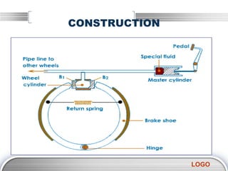

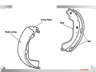
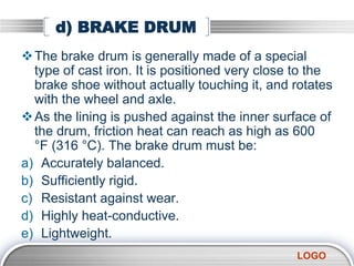
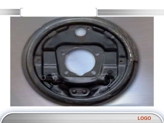
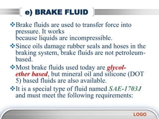
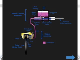


The document provides an overview of hydraulic brake systems, including their construction, operation, advantages, and disadvantages. Key components such as the master cylinder, wheel cylinder, brake shoes, and brake fluid are detailed, emphasizing their roles in the braking process. The principles of operation based on Pascal's law and the classifications of brakes are also discussed.


