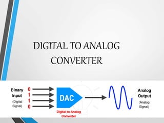
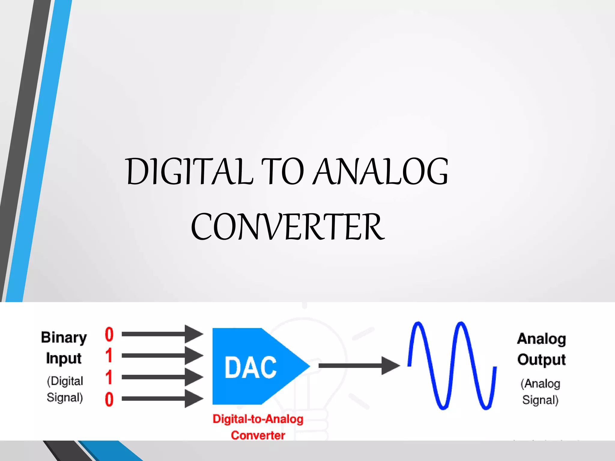
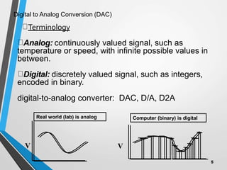
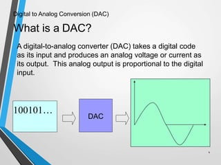
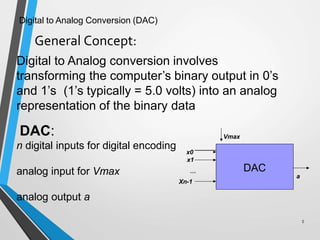
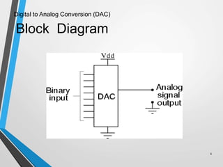
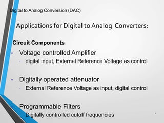
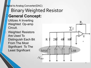
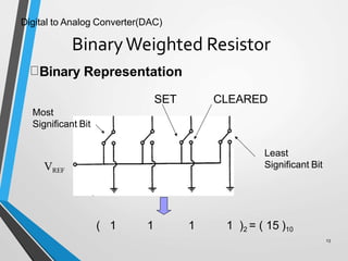
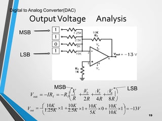
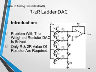
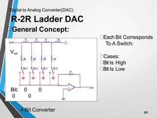
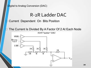
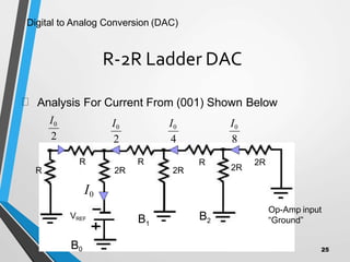
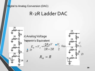
DIGITAL TO ANALOG
CONVERTER
Outline’s
 Basic concept about DAC
 Application
 Operation of Weighted Resistor DAC
 Operation of R-2R Ladder DAC
Digital to Analog Conversion (DAC)
4
Digital to Analog Conversion (DAC)
Terminology
Analog: continuously valued signal, such as
temperature or speed, with infinite possible values in
between.
Digital: discretely valued signal, such as integers,
encoded in binary.
digital-to-analog converter: DAC, D/A, D2A
Real world (lab) is analog
V
t
Computer (binary) is digital
V
5
What is a DAC?
4
DAC
100101…
Digital to Analog Conversion (DAC)
A digital-to-analog converter (DAC) takes a digital code
as its input and produces an analog voltage or current as
its output. This analog output is proportional to the digital
input.
Digital to Analog Conversion (DAC)
Digital to Analog conversion involves
transforming the computer’s binary output in 0’s
and 1’s (1’s typically = 5.0 volts) into an analog
representation of the binary data
DAC:
n digital inputs for digital encoding
analog input for Vmax
analog output a
DAC
Vmax
x0
x1
Xn-1
…
a
General Concept:
5
Digital to Analog Conversion (DAC)
Block Diagram
6
Digital to Analog Conversion (DAC)
Applications for Digital toAnalog Converters:
7
Circuit Components
• Voltage controlled Amplifier
• digital input, External Reference Voltage as control
• Digitally operated attenuator
• External Reference Voltage as input, digital control
• Programmable Filters
• Digitally controlled cutoff frequencies
Digital to Analog Conversion (DAC)
Applications for Digital to Analog
Converters:
8
Digital Audio
CD Players MP3 Players Telephone
Digital to Analog Conversion (DAC)
Function Generators
Digital Oscilloscopes
Digital Input
Analog Output
Signal Generators
Sine wave generation
Square wave generation
Triangle wave generation
Random noise generation
Applications for Digital to Analog
Converters:
9
Digital to Analog Conversion (DAC)
Applications for Digital to Analog
Converters:
10
Motor Controllers
Cruise
Control
Valve Control Motor Control
Digital to Analog Conversion (DAC)
Many types of DACs available
11
– Binary Weighted Resistor
– R-2R Ladder
– Multiplier DAC
– Non-Multiplier DAC
• Among them Weighted & R-2R are
commonly used.
Digital to Analog Converter(DAC)
BinaryWeighted Resistor
12
Distinguish Each Bit
From The Most
Significant To The
Least Significant
Rf
V
o
-VREF
Ii
LSB
R 2R 4R 8R
MSB
General Concept:
Utilizes A Inverting
Weighted Op-amp
Circuit.
Weighted Resistors
Are Used To
Digital to Analog Converter(DAC)
Binary Representation
SET CLEARED
Most
Significant Bit
VREF
Least
Significant Bit
( 1
BinaryWeighted Resistor
13
1 1 1 )2 = ( 15 )10
Digital to Analog Converter(DAC)

V V V V
2R 4R 8R 
2
3
4

V  IR  R  1
f
 R
f
out
MSB LSB
MSB
LSB
5K 10K
  10K
1 
10K
Vout 


1.25K 2.5K

1
10K
0 
10K
1  13V
OutputVoltage Analysis
19
Digital to Analog Converter(DAC)
15
BinaryWeighted Resistor
Advantages
Simple Analysis
Fast Conversion
Disadvantages
This setup requires a wide range of accurate values of
resistors
A 10 bit DAC needs resistors ranging from R to
R/1024.
Requires low switch resistances in transistors
Usually limited to 8-bit resolution.
R-2R Ladder DAC
Introduction:
C
Problem With The
Weighted Resistor DA
Is Solved.
Only R & 2R Value Of
Resistor Are Required.
Vout
16
Digital to Analog Converter(DAC)
R-2R Ladder DAC
0
Bit: 0
0 0
Each Bit Corresponds
To A Switch:
Cases:
Bit Is High
Bit Is Low
4-Bit Converter
Vref
General Concept:
23
R-2R Ladder DAC
Current Dependent On Bits Position
The Current Is Divided By A Factor Of 2 At Each Node
Digital to Analog Conversion (DAC)
24
R-2R Ladder DAC
I0
VREF
Analysis For Current From (001) Shown Below
R
R R R 2R
2R
2R
2R
Op-Amp input
“Ground”
B0
I0 I0 I0
2 4 8
B1
B2
2
I0
Digital to Analog Conversion (DAC)
25
R-2R Ladder DAC
• OutputAnalogVoltage
• Using Thevenin’s Equivalent
• EquivalentCircuit :
• D
• D
A
B
C
2RV V
0
 0
A
th
E V
Rth
2R2R 2
 R
B
C
Digital to Analog Conversion (DAC)
26
R-2R Ladder DAC
21
Advantages
• Only Two Resistor Values(R & 2R)
• Does Not Require High Precision
Resistors.
Disadvantages
Lower Conversion Speed Than Binary Weighted
DAC
Digital to Analog Conversion (DAC)
THANK YOU
BY:
ASWANTH VISHNU S
BALA SHANMUGI P
DHANUSHKUMAR K S
CHETHANA SREE R

dsd.pptx

  • 1.
  • 2.
    Outline’s  Basic conceptabout DAC  Application  Operation of Weighted Resistor DAC  Operation of R-2R Ladder DAC Digital to Analog Conversion (DAC) 4
  • 3.
    Digital to AnalogConversion (DAC) Terminology Analog: continuously valued signal, such as temperature or speed, with infinite possible values in between. Digital: discretely valued signal, such as integers, encoded in binary. digital-to-analog converter: DAC, D/A, D2A Real world (lab) is analog V t Computer (binary) is digital V 5
  • 4.
    What is aDAC? 4 DAC 100101… Digital to Analog Conversion (DAC) A digital-to-analog converter (DAC) takes a digital code as its input and produces an analog voltage or current as its output. This analog output is proportional to the digital input.
  • 5.
    Digital to AnalogConversion (DAC) Digital to Analog conversion involves transforming the computer’s binary output in 0’s and 1’s (1’s typically = 5.0 volts) into an analog representation of the binary data DAC: n digital inputs for digital encoding analog input for Vmax analog output a DAC Vmax x0 x1 Xn-1 … a General Concept: 5
  • 6.
    Digital to AnalogConversion (DAC) Block Diagram 6
  • 7.
    Digital to AnalogConversion (DAC) Applications for Digital toAnalog Converters: 7 Circuit Components • Voltage controlled Amplifier • digital input, External Reference Voltage as control • Digitally operated attenuator • External Reference Voltage as input, digital control • Programmable Filters • Digitally controlled cutoff frequencies
  • 8.
    Digital to AnalogConversion (DAC) Applications for Digital to Analog Converters: 8 Digital Audio CD Players MP3 Players Telephone
  • 9.
    Digital to AnalogConversion (DAC) Function Generators Digital Oscilloscopes Digital Input Analog Output Signal Generators Sine wave generation Square wave generation Triangle wave generation Random noise generation Applications for Digital to Analog Converters: 9
  • 10.
    Digital to AnalogConversion (DAC) Applications for Digital to Analog Converters: 10 Motor Controllers Cruise Control Valve Control Motor Control
  • 11.
    Digital to AnalogConversion (DAC) Many types of DACs available 11 – Binary Weighted Resistor – R-2R Ladder – Multiplier DAC – Non-Multiplier DAC • Among them Weighted & R-2R are commonly used.
  • 12.
    Digital to AnalogConverter(DAC) BinaryWeighted Resistor 12 Distinguish Each Bit From The Most Significant To The Least Significant Rf V o -VREF Ii LSB R 2R 4R 8R MSB General Concept: Utilizes A Inverting Weighted Op-amp Circuit. Weighted Resistors Are Used To
  • 13.
    Digital to AnalogConverter(DAC) Binary Representation SET CLEARED Most Significant Bit VREF Least Significant Bit ( 1 BinaryWeighted Resistor 13 1 1 1 )2 = ( 15 )10
  • 14.
    Digital to AnalogConverter(DAC)  V V V V 2R 4R 8R  2 3 4  V  IR  R  1 f  R f out MSB LSB MSB LSB 5K 10K   10K 1  10K Vout    1.25K 2.5K  1 10K 0  10K 1  13V OutputVoltage Analysis 19
  • 15.
    Digital to AnalogConverter(DAC) 15 BinaryWeighted Resistor Advantages Simple Analysis Fast Conversion Disadvantages This setup requires a wide range of accurate values of resistors A 10 bit DAC needs resistors ranging from R to R/1024. Requires low switch resistances in transistors Usually limited to 8-bit resolution.
  • 16.
    R-2R Ladder DAC Introduction: C ProblemWith The Weighted Resistor DA Is Solved. Only R & 2R Value Of Resistor Are Required. Vout 16 Digital to Analog Converter(DAC)
  • 17.
    Digital to AnalogConverter(DAC) R-2R Ladder DAC 0 Bit: 0 0 0 Each Bit Corresponds To A Switch: Cases: Bit Is High Bit Is Low 4-Bit Converter Vref General Concept: 23
  • 18.
    R-2R Ladder DAC CurrentDependent On Bits Position The Current Is Divided By A Factor Of 2 At Each Node Digital to Analog Conversion (DAC) 24
  • 19.
    R-2R Ladder DAC I0 VREF AnalysisFor Current From (001) Shown Below R R R R 2R 2R 2R 2R Op-Amp input “Ground” B0 I0 I0 I0 2 4 8 B1 B2 2 I0 Digital to Analog Conversion (DAC) 25
  • 20.
    R-2R Ladder DAC •OutputAnalogVoltage • Using Thevenin’s Equivalent • EquivalentCircuit : • D • D A B C 2RV V 0  0 A th E V Rth 2R2R 2  R B C Digital to Analog Conversion (DAC) 26
  • 21.
    R-2R Ladder DAC 21 Advantages •Only Two Resistor Values(R & 2R) • Does Not Require High Precision Resistors. Disadvantages Lower Conversion Speed Than Binary Weighted DAC Digital to Analog Conversion (DAC)
  • 22.
    THANK YOU BY: ASWANTH VISHNUS BALA SHANMUGI P DHANUSHKUMAR K S CHETHANA SREE R