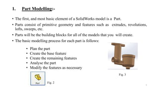
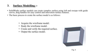
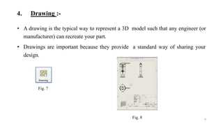
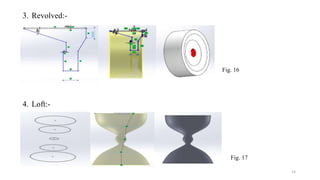
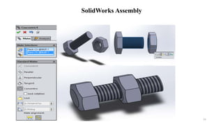
Presentation
On
SolidWorks
Presented by
Aditya Soni
B.Tech. (Mechanical Engineering)
Industrial Training at
INTERNSHALA TRAININGS
Prayagraj
Mechanical Engineering Department
Shambhunath Institute of Engineering & Technology, Jhalwa, Prayagraj, Uttar Pradesh
1
CONTENT
• Introduction
• Modules in SolidWorks
• Getting Start
• Sketcher
• Commands
• SolidWorks Assembly
2
INTRODUCTION
• SolidWorks is a 3D mechanical CAD program that runs on Microsoft Window which
was developed by SolidWorks corporation, headquartered in U.S.A., a subsidiary of
Dassault Systems.
• SolidWorks is used by students, designers, engineers, and other professionals to
produce simple and complex parts, assemblies, and drawings.
• SolidWorks is a 3D solid modeling package which allows users to develop full solid
models in a simulated environment for both design and analysis.
Fig. 1
3
MODULES IN SOLIDWORKS
1. Part Modelling
2. Assembly Modelling
3. Surface Modelling
4. Drawing
4
1. Part Modelling:-
• The first, and most basic element of a SolidWorks model is a Part.
• Parts consist of primitive geometry and features such as extrudes, revolutions,
lofts, sweeps, etc.
• Parts will be the building blocks for all of the models that you will create.
• The basic modelling process for each part is follows:
5
• Plan the part
• Create the base feature
• Create the remaining features
• Analyse the part
• Modify the features as necessary
Fig. 2
Fig. 3
2. Assembly Modelling :-
• Assembly is a combination of two or more components using parametric
relationship.
• In SolidWorks, these relationships is called mates.
• Mates enable you to control part movement with respect to each other.
6
Fig. 4
Fig. 5
3. Surface Modelling :-
• SolidWorks surface module can create complex surface using loft and sweeps with guide
curves, drag handles for easy control and innovation surface features.
• The basic process to create the surface model is as follows:
7
• Acquire the wireframe model.
• Study the wireframe model.
• Create and verify the required surface.
• Output the surface model.
Fig. 6
4. Drawing :-
• A drawing is the typical way to represent a 3D model such that any engineer (or
manufacturer) can recreate your part.
• Drawings are important because they provide a standard way of sharing your
design.
8
Fig. 7
Fig. 8
9
GETTING STARTED
Fig. 9
SKETCHER
• In the part, click the sketches tab in command manager and the sketch toolbar
appears.
• Click the sketch icon tools>sketch entities.
• Select any reference plane to sketch.
10
Fig. 11
Fig. 10
 Sketcher Commands are:
• Line
• Circle
• Arc
• Ellipsis
• Rectangle
• Polyline
• Polygon
11
Fig. 12
Commands
 3D Features Commands :-
1. Extrude
2. Extrude Cut
3. Swept
4. Swept Cut
5. Revolved
6. Revolved Cut
7. Loft
8. Loft Cut
9. Pattern
10. Shell
11. Rib
12. Draft
13. Wrap
12
Circular Pattern
Fill Pattern
Linear Pattern
Curve Driven Pattern
Fig. 13
• Uses of some 3D features commands:-
13
1. Extrude:-
Fig. 14
2. Swept:-
Fig. 15
14
3. Revolved:-
Fig. 16
4. Loft:-
Fig. 17
15
SolidWorks Assembly
16
Thank You

Solid works ppt

  • 1.
    Presentation On SolidWorks Presented by Aditya Soni B.Tech.(Mechanical Engineering) Industrial Training at INTERNSHALA TRAININGS Prayagraj Mechanical Engineering Department Shambhunath Institute of Engineering & Technology, Jhalwa, Prayagraj, Uttar Pradesh 1
  • 2.
    CONTENT • Introduction • Modulesin SolidWorks • Getting Start • Sketcher • Commands • SolidWorks Assembly 2
  • 3.
    INTRODUCTION • SolidWorks isa 3D mechanical CAD program that runs on Microsoft Window which was developed by SolidWorks corporation, headquartered in U.S.A., a subsidiary of Dassault Systems. • SolidWorks is used by students, designers, engineers, and other professionals to produce simple and complex parts, assemblies, and drawings. • SolidWorks is a 3D solid modeling package which allows users to develop full solid models in a simulated environment for both design and analysis. Fig. 1 3
  • 4.
    MODULES IN SOLIDWORKS 1.Part Modelling 2. Assembly Modelling 3. Surface Modelling 4. Drawing 4
  • 5.
    1. Part Modelling:- •The first, and most basic element of a SolidWorks model is a Part. • Parts consist of primitive geometry and features such as extrudes, revolutions, lofts, sweeps, etc. • Parts will be the building blocks for all of the models that you will create. • The basic modelling process for each part is follows: 5 • Plan the part • Create the base feature • Create the remaining features • Analyse the part • Modify the features as necessary Fig. 2 Fig. 3
  • 6.
    2. Assembly Modelling:- • Assembly is a combination of two or more components using parametric relationship. • In SolidWorks, these relationships is called mates. • Mates enable you to control part movement with respect to each other. 6 Fig. 4 Fig. 5
  • 7.
    3. Surface Modelling:- • SolidWorks surface module can create complex surface using loft and sweeps with guide curves, drag handles for easy control and innovation surface features. • The basic process to create the surface model is as follows: 7 • Acquire the wireframe model. • Study the wireframe model. • Create and verify the required surface. • Output the surface model. Fig. 6
  • 8.
    4. Drawing :- •A drawing is the typical way to represent a 3D model such that any engineer (or manufacturer) can recreate your part. • Drawings are important because they provide a standard way of sharing your design. 8 Fig. 7 Fig. 8
  • 9.
  • 10.
    SKETCHER • In thepart, click the sketches tab in command manager and the sketch toolbar appears. • Click the sketch icon tools>sketch entities. • Select any reference plane to sketch. 10 Fig. 11 Fig. 10
  • 11.
     Sketcher Commandsare: • Line • Circle • Arc • Ellipsis • Rectangle • Polyline • Polygon 11 Fig. 12 Commands
  • 12.
     3D FeaturesCommands :- 1. Extrude 2. Extrude Cut 3. Swept 4. Swept Cut 5. Revolved 6. Revolved Cut 7. Loft 8. Loft Cut 9. Pattern 10. Shell 11. Rib 12. Draft 13. Wrap 12 Circular Pattern Fill Pattern Linear Pattern Curve Driven Pattern Fig. 13
  • 13.
    • Uses ofsome 3D features commands:- 13 1. Extrude:- Fig. 14 2. Swept:- Fig. 15
  • 14.
  • 15.
  • 16.