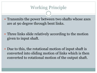
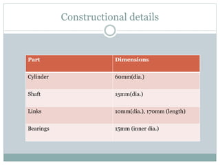
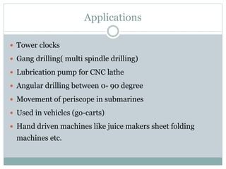
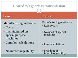
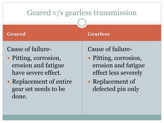
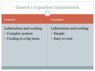
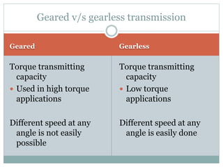
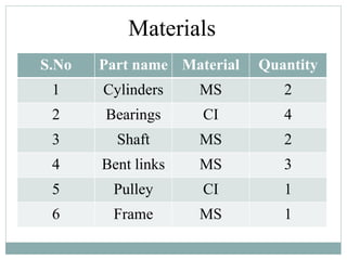
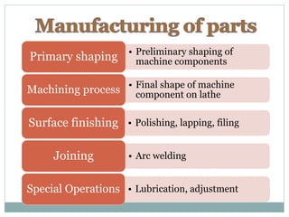
PREPARING A WORKING MODEL OF
GEARLESS TRANSMISSION
A
project on
BY
•ATUL KUMAR (1010440014)
•AKASH DEEP MAURYA(1010440002)
•AMIT KUMAR PATEL(1010440005)
•PHURBA BHUTIA (1010440055)
•PRAWAL BISTA (1010440056)
OVERVIEW
 Need of gearless transmission.
 What is gearless transmission?
 Applications
 Comparison
 Materials
 Specification and manufacturing of parts
 Advantages
 Limitations
 Possible advances
 Conclusion
Need Of Gearless Transmission
 Today’s world requires speed on each and every field.
 Engineers are constantly confronted to the
challenges of efficient transmission of power.
 Gears are costly to manufacture.
 It is needed to further increase the efficiency of
transmission which cannot be done using geared
transmission
 Gearless transmission mechanism is capable of
transmitting power at any angle without any gears
being manufactured.
What Is Gearless Transmission?
 Also called elbow mechanism
 It is an ingenious link mechanism of slider and
kinematic chain principle.
 Transmits power at any angle without utilising gears
Working Principle
 Transmits the power between two shafts whose axes
are at 90 degree through bent links.
 Three links slide relatively according to the motion
given to input shaft.
 Due to this, the rotational motion of input shaft is
converted into sliding motion of links which is then
converted to rotational motion of the output shaft.
Constructional details
Part Dimensions
Cylinder 60mm(dia.)
Shaft 15mm(dia.)
Links 10mm(dia.), 170mm (length)
Bearings 15mm (inner dia.)
Applications
 Tower clocks
 Gang drilling( multi spindle drilling)
 Lubrication pump for CNC lathe
 Angular drilling between 0- 90 degree
 Movement of periscope in submarines
 Used in vehicles (go-carts)
 Hand driven machines like juice makers sheet folding
machines etc.
Geared Gearless
Manufacturing methods-
 Costly.
 manufactured on
special purpose
machines
 Complex calculations
 No interchangeability
Manufacturing methods-
 Less costly.
 No need of special
machines
 Less calculations
 Freedom of
interchangeability
Geared v/s gearless transmission
Geared Gearless
Cause of failure-
 Pitting, corrosion,
erosion and fatigue
have severe effect.
 Replacement of entire
gear set needs to be
done.
Cause of failure-
 Pitting, corrosion,
erosion and fatigue
effect less severely
 Replacement of
defected pin only
Geared v/s gearless transmission
Geared Gearless
Lubrication and cooling-
 Complex system
 Cooling is a big issue
Lubrication and cooling
 Simple
 Easy to cool
Geared v/s gearless transmission
Geared Gearless
Torque transmitting
capacity
 Used in high torque
applications
Different speed at any
angle is not easily
possible
Torque transmitting
capacity
 Low torque
applications
Different speed at any
angle is easily done
Geared v/s gearless transmission
Materials
S.No Part name Material Quantity
1 Cylinders MS 2
2 Bearings CI 4
3 Shaft MS 2
4 Bent links MS 3
5 Pulley CI 1
6 Frame MS 1
• Preliminary shaping of
machine componentsPrimary shaping
• Final shape of machine
component on latheMachining process
• Polishing, lapping, filingSurface finishing
• Arc weldingJoining
• Lubrication, adjustmentSpecial Operations
ADVANTAGES
 Complete freedom of Interchangeability.
 More efficient than gear.
 Power could be transferred to any desired angle.
 Ease of manufacturing.
 Misalignment of shafts can be tolerated to some
extent.
 Simpler cooling system
 Low cost of manufacturing.
 Portability of parts.
LIMITATIONS
 Does not work at very low starting torque.
 Improper hole drilling could pose much problem.
 Sudden load would cause mechanism breakdown.
 Links are to be replaced after certain cycle time.
 Speed ratio is always constant 1:1.
Future Aspects
 Torque bearing capacity can be improved.
 Flexible bent links can be used.
 Has a bright future in automation and robotics.
 Can be used in automobile industry in near future.
• The model works correctly as per
the design
• With the help of this system, we
can efficiently reduce the cost in
power transmission and
• Further advancement in this
technology can be made.
Conclusion
Gearless transmission system

Gearless transmission system

  • 1.
    PREPARING A WORKINGMODEL OF GEARLESS TRANSMISSION A project on BY •ATUL KUMAR (1010440014) •AKASH DEEP MAURYA(1010440002) •AMIT KUMAR PATEL(1010440005) •PHURBA BHUTIA (1010440055) •PRAWAL BISTA (1010440056)
  • 2.
    OVERVIEW  Need ofgearless transmission.  What is gearless transmission?  Applications  Comparison  Materials  Specification and manufacturing of parts  Advantages  Limitations  Possible advances  Conclusion
  • 3.
    Need Of GearlessTransmission  Today’s world requires speed on each and every field.  Engineers are constantly confronted to the challenges of efficient transmission of power.  Gears are costly to manufacture.  It is needed to further increase the efficiency of transmission which cannot be done using geared transmission  Gearless transmission mechanism is capable of transmitting power at any angle without any gears being manufactured.
  • 4.
    What Is GearlessTransmission?  Also called elbow mechanism  It is an ingenious link mechanism of slider and kinematic chain principle.  Transmits power at any angle without utilising gears
  • 5.
    Working Principle  Transmitsthe power between two shafts whose axes are at 90 degree through bent links.  Three links slide relatively according to the motion given to input shaft.  Due to this, the rotational motion of input shaft is converted into sliding motion of links which is then converted to rotational motion of the output shaft.
  • 8.
    Constructional details Part Dimensions Cylinder60mm(dia.) Shaft 15mm(dia.) Links 10mm(dia.), 170mm (length) Bearings 15mm (inner dia.)
  • 9.
    Applications  Tower clocks Gang drilling( multi spindle drilling)  Lubrication pump for CNC lathe  Angular drilling between 0- 90 degree  Movement of periscope in submarines  Used in vehicles (go-carts)  Hand driven machines like juice makers sheet folding machines etc.
  • 10.
    Geared Gearless Manufacturing methods- Costly.  manufactured on special purpose machines  Complex calculations  No interchangeability Manufacturing methods-  Less costly.  No need of special machines  Less calculations  Freedom of interchangeability Geared v/s gearless transmission
  • 11.
    Geared Gearless Cause offailure-  Pitting, corrosion, erosion and fatigue have severe effect.  Replacement of entire gear set needs to be done. Cause of failure-  Pitting, corrosion, erosion and fatigue effect less severely  Replacement of defected pin only Geared v/s gearless transmission
  • 12.
    Geared Gearless Lubrication andcooling-  Complex system  Cooling is a big issue Lubrication and cooling  Simple  Easy to cool Geared v/s gearless transmission
  • 13.
    Geared Gearless Torque transmitting capacity Used in high torque applications Different speed at any angle is not easily possible Torque transmitting capacity  Low torque applications Different speed at any angle is easily done Geared v/s gearless transmission
  • 14.
    Materials S.No Part nameMaterial Quantity 1 Cylinders MS 2 2 Bearings CI 4 3 Shaft MS 2 4 Bent links MS 3 5 Pulley CI 1 6 Frame MS 1
  • 15.
    • Preliminary shapingof machine componentsPrimary shaping • Final shape of machine component on latheMachining process • Polishing, lapping, filingSurface finishing • Arc weldingJoining • Lubrication, adjustmentSpecial Operations
  • 16.
    ADVANTAGES  Complete freedomof Interchangeability.  More efficient than gear.  Power could be transferred to any desired angle.  Ease of manufacturing.  Misalignment of shafts can be tolerated to some extent.  Simpler cooling system  Low cost of manufacturing.  Portability of parts.
  • 17.
    LIMITATIONS  Does notwork at very low starting torque.  Improper hole drilling could pose much problem.  Sudden load would cause mechanism breakdown.  Links are to be replaced after certain cycle time.  Speed ratio is always constant 1:1.
  • 18.
    Future Aspects  Torquebearing capacity can be improved.  Flexible bent links can be used.  Has a bright future in automation and robotics.  Can be used in automobile industry in near future.
  • 19.
    • The modelworks correctly as per the design • With the help of this system, we can efficiently reduce the cost in power transmission and • Further advancement in this technology can be made. Conclusion

Editor's Notes

  • #13 . Due to slidingcontract, between pins and cylinders, heat generated   is more and thuseffective cooling is a must