This document discusses the objectives and content of a course on smart manufacturing. The course aims to teach students about computer-aided design, manufacturing, and additive manufacturing processes. It covers topics like CAD standards, including graphics standards like Graphical Kernel System (GKS) and data exchange standards like IGES and STEP. The syllabus outlines units on CAD standards that will discuss topics such as graphics languages, data exchange formats, and communication standards.


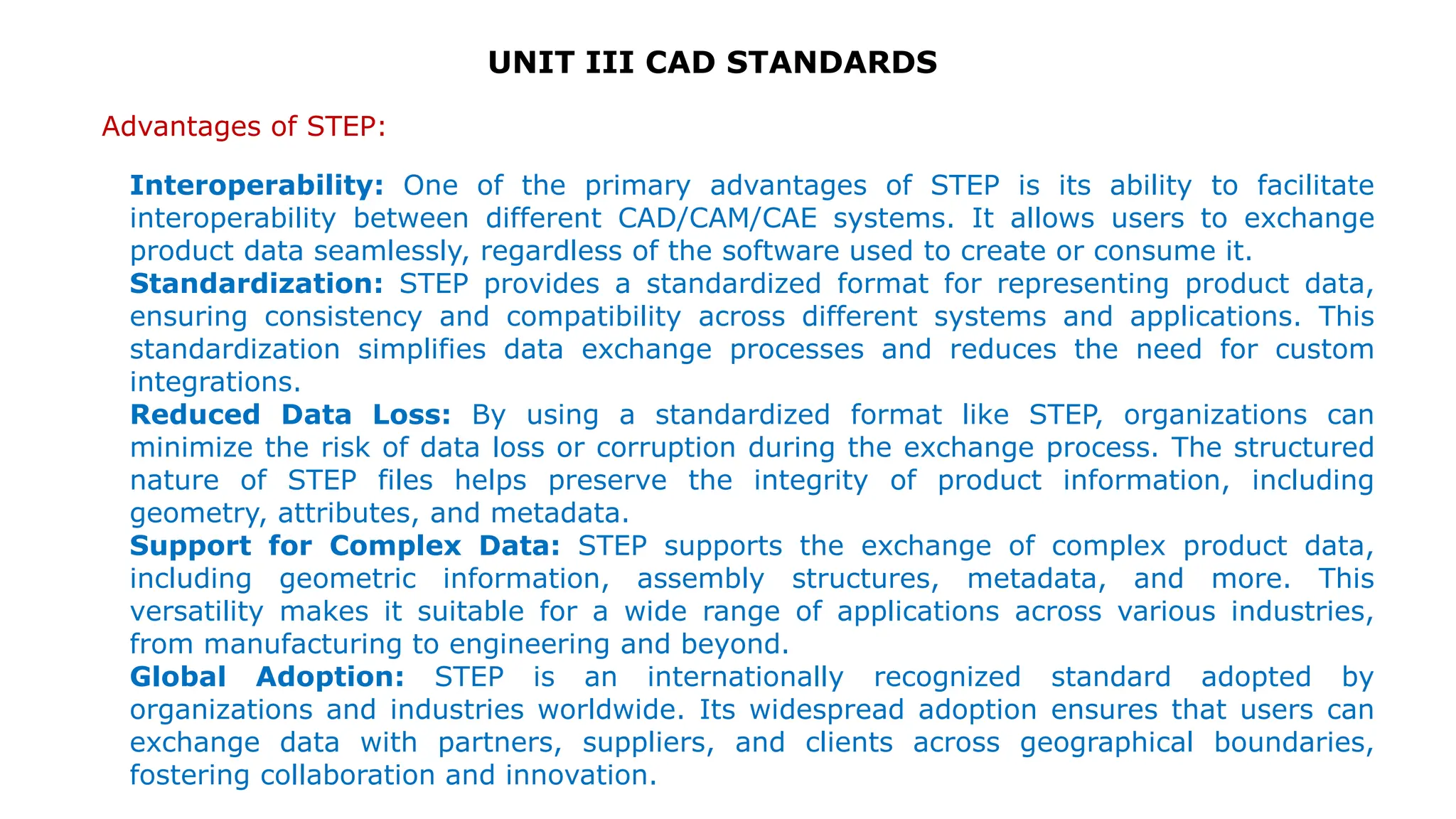
![UNIT III CAD STANDARDS
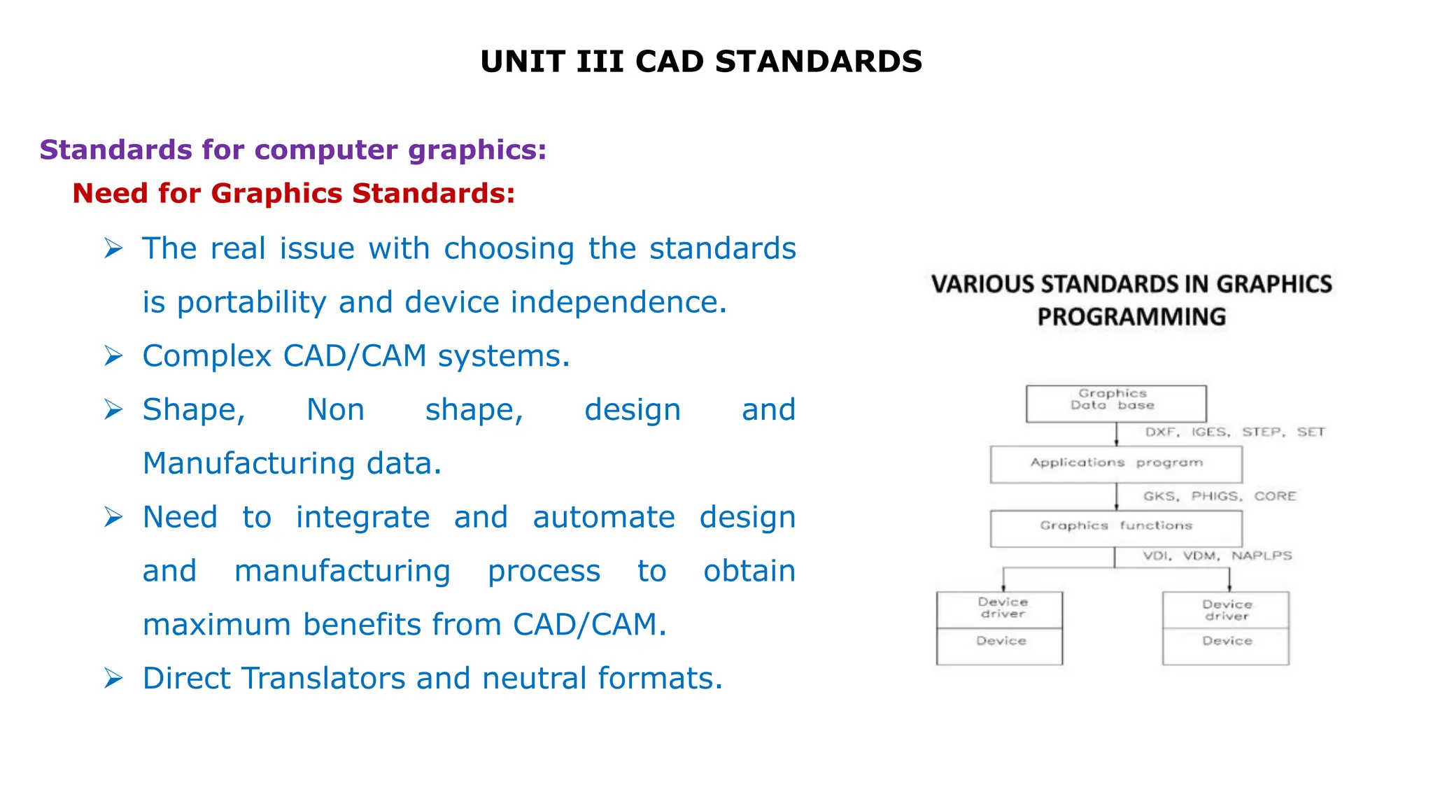
Various Interface Standards Exchange Format
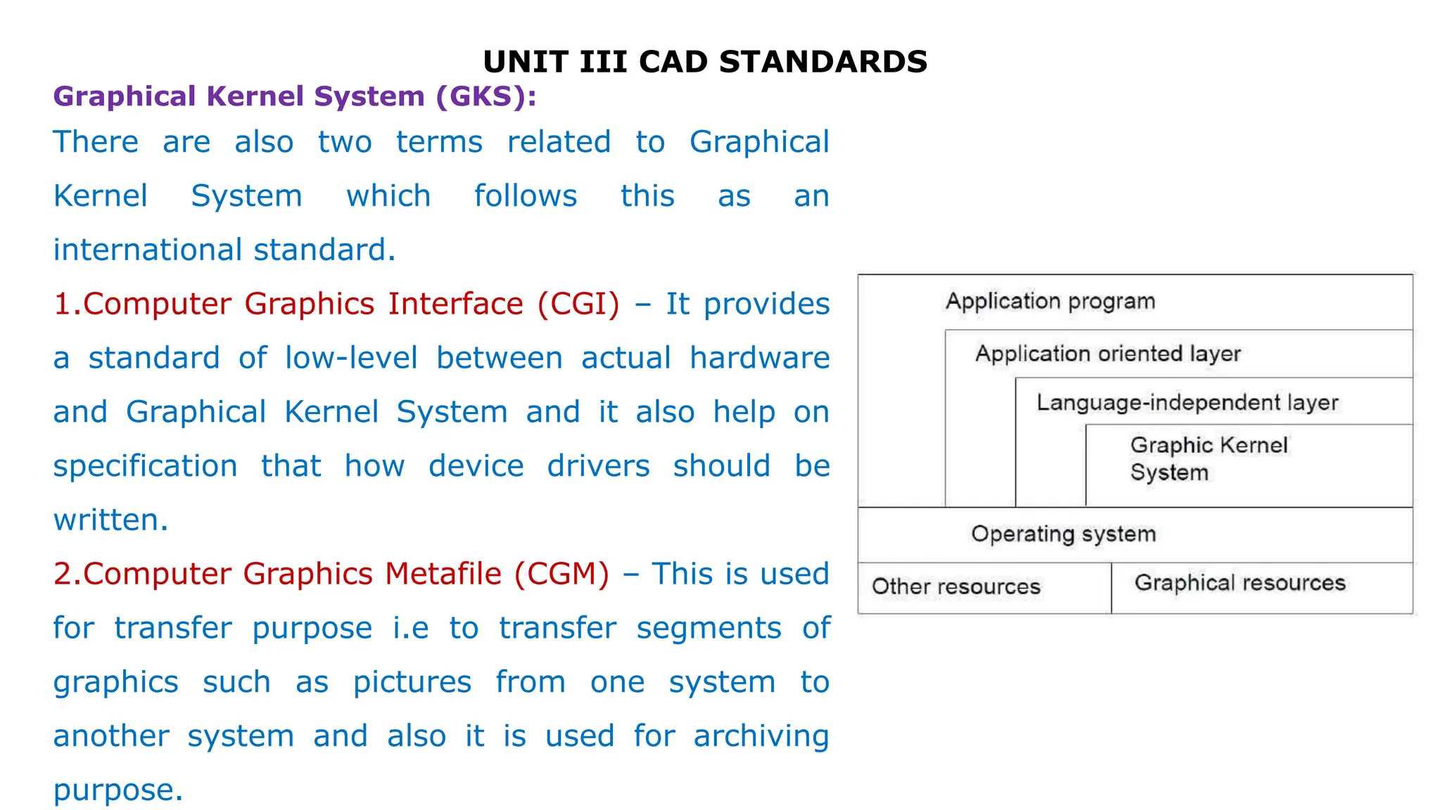
GKS ( Graphical Kernel System)
PHIGS (Programmer’s Hierarchical Interface for GraphicS)
GKS -3D
IGES (Initial Graphics Exchange Specification)
DXF (Drawing eXchange Format)
STEP (STandard for the Exchange of Product Model Data)
CALS (Continuous Acquisition and Life cycle Support)
ACIS ( *.sat ) [Alan, Charles, Ian's System]
OpenGL – Open Graphics Laboratory
DMIS (Dimensional Measurement Interface Specification)
VDI (Virtual Device Interface)
CGI (Computer Graphics Interface)
VDM (Virtual DeviceMetafile)
CGM (Computer Graphics Metafile)
GKSM (GKS Metafile)
PDES (Product Data Exchange Standards)
VRML (Virtual Reality Modelling Language)](https://image.slidesharecdn.com/unit3-240314004950-0e0ae353/75/CAD-STANDARDS-SMART-MANUFACTURING-MECH-7-2048.jpg)