The document discusses the evolution of 4G cellular systems, specifically Long Term Evolution-Advanced (LTE-Advanced). It provides an overview of the key technologies being considered for LTE-Advanced to meet its performance targets, including carrier aggregation, enhanced MIMO techniques, coordinated multipoint transmission/reception, and relaying strategies. The network architecture developed by 3GPP to support LTE and future radio access technologies is also highlighted.
![218 I.F. Akyildiz et al. / Physical Communication 3 (2010) 217–244
the ITU-R framework for 4G systems was not in place, and
later research and measurements confirmed that the sys-
tem did not fully comply with ITU 4G requirements. For
this reason, the term 3.9G has been widely used with the
expectation of their evolving towards official 4G status in
due course.
Before 3GPP started working in the real 4G wire-
less technology, minor changes were introduced in LTE
through Release 9. In particular, femtocells and dual-layer
beamforming, predecessors of future LTE-Advanced tech-
nologies, have been added to the standard. The formal
definition of the fourth generation wireless, known as the
International Mobile Telecommunications Advanced (IMT-
Advanced) project, was finally published by ITU-R through
a Circular Letter in July 2008 with a call for candidate ra-
dio interface technologies (RITs) [1]. In October 2009, six
technologies were submitted seeking for approval as inter-
national 4G communications standard. 3GPP’s candidate is
LTE-Advanced, the backward-compatible enhancement of
LTE Release 8 that will be fully specified in 3GPP Release
10 [2]. By backward compatibility, it is meant that it should
be possible to deploy LTE-Advanced in a spectrum already
occupied by LTE with no impact on the existing LTE termi-
nals. Other candidate technologies are IEEE 802.16m and
China’s Ministry of Industry and Information Technology
TD-LTE-Advanced (LTE-Advanced TDD specification) [3,4].
The set of IMT-Advanced high-level requirements
established by the ITU-R in [5] is as follows.
• A high degree of commonality of functionality world-
wide while retaining the flexibility to support a wide
range of services and applications in a cost-efficient
manner.
• Compatibility of services within IMT and with fixed
networks.
• Compatibility of internetworking with other radio
access systems.
• High-quality mobile devices.
• User equipment suitable for worldwide use.
• User-friendly applications, services, and equipment.
• Worldwide roaming capability.
• Enhanced peak rates to support advanced services
and applications (100 Mbit/s for high mobility and
1 Gbit/s for low mobility were established as targets for
research).
All the above requirements, except for the last one, are
high level, i.e. they do not quantify the performance re-
quirements; besides, they have largely been pursued by the
industry already. When it comes to a detailed description
of the IMT-Advanced requirements, explicit targets have
been set for average and cell-edge performance in addition
to the usual peak data rates. This was a necessary issue to
be addressed since they define the experience for the typ-
ical user.
The requirements for LTE-Advanced were accordingly
set to achieve or even enhance IMT-Advanced. However,
as stated in [6], the target for average spectrum efficiency
and cell-edge user throughput efficiency should be given a
higher priority than the target for peak spectrum efficiency
and Voice-over-IP (VoIP) capacity. Therefore, the solution
proposals of LTE-Advanced, the main ones of which are
covered by this paper, focus on the challenge of raising
the average and cell-edge performance. The relationship
among the requirements of LTE, LTE-Advanced, and IMT-
Advanced are shown in Table 1.
Other important requirements are the already men-
tioned backward compatibility of LTE-Advanced with LTE
and the spectrum flexibility, i.e., the capacity of LTE-
Advanced to be deployed in different allocated spectra
since each region or country has different regulations. The
main issue now is to develop the appropriate technolo-
gies that allow LTE-Advanced to meet the proposed targets.
From a link performance perspective, LTE already achieves
data rates very close to the Shannon limit, which means
that the main effort must be made in the direction of im-
proving the Signal-to-Interference-and-Noise Ratio (SINR)
experienced by the users and hence provide data rates over
a larger portion of the cell.
The remainder of this paper is organized as follows. In
Section 2, we provide an overview of the network archi-
tecture that will support the LTE and LTE-Advanced air in-
terfaces. Then, we cover the concept and challenges of the
four research categories that, according to 3GPP, consti-
tute the pillars of the LTE-Advanced system. In Section 3,
we present LTE-Advanced spectrum issues: bandwidth ag-
gregation, a technology that aims at increasing the system
bandwidth by aggregating different carriers, and spectrum
sharing techniques for heterogeneous networks. The new
enhanced MIMO techniques in both the downlink and the
uplink for LTE-Advanced are introduced in Section 4. In
Section 5, we describe enhanced Node B cooperation tech-
niques in the framework of LTE-Advanced, grouped un-
der the name of coordinated multipoint transmission and
reception (CoMP). We present relaying strategies in Sec-
tion 6. Finally, we conclude the paper with Section 7.
2. Network architecture
3GPP specified in its Release 8 the elements and re-
quirements of the EPS architecture that will serve as a
basis for the next-generation networks [7]. The specifica-
tions contain two major work items, namely LTE and SAE,
that led to the specification of the Evolved Packet Core
(EPC), Evolved Universal Terrestrial Radio Access Network
(E-UTRAN), and Evolved Universal Terrestrial Radio Access
(E-UTRA), each of which corresponds to the core network,
radio access network, and air interface of the whole sys-
tem, respectively. The EPS provides IP connectivity be-
tween a User Equipment (UE) and an external packet data
network using E-UTRAN. In Fig. 1, we provide an overview
of the EPS, other legacy Packet and Circuit Switched ele-
ments and 3GPP RANs, along with the most important in-
terfaces. In the services network, only the Policy and Charg-
ing Rules Function (PCRF) and the Home Subscriber Server
(HSS) are included, for simplicity.
In the context of 4G systems, both the air interface and
the radio access network are being enhanced or redefined,
but so far the core network architecture, i.e. the EPC, is not
undergoing major changes from the already standardized
SAE architecture. Therefore, in this section we give an
overview of the E-UTRAN architecture and functionalities
defined for the LTE-Advanced systems and the main EPC
node functionalities, shared by Releases 8, 9, and 10.](https://image.slidesharecdn.com/georgiatech2010-150530225436-lva1-app6891/85/Georgia-tech-2010-2-320.jpg)
![I.F. Akyildiz et al. / Physical Communication 3 (2010) 217–244 219
Table 1
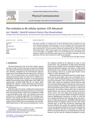
LTE, LTE-Advanced, and IMT-Advanced performance targets for downlink (DL) and uplink (UL).
Item Transmission path Antenna configuration LTE (Rel. 8) LTE-Advanced IMT-Advanced
Peak data rate
DL 8 × 8 300 Mbps 1 Gbps 1 Gbps
UL 4 × 4 75 Mbps 500 Mbps –
Peak spectrum efficiency (bps/Hz)
DL 8 × 8 15 30 15
UL 4 × 4 3.75 15 6.75
Capacity (bps/Hz/cell)
DL
2 × 2 1.69 2.4 –
4 × 2 1.87 2.6 2.2
4 × 4 2.67 3.7 –
UL
1 × 2 0.74 1.2 –
2 × 4 – 2.0 1.4
Cell-edge user throughput (bps/Hz/cell/user)
DL
2 × 2 0.05 0.07 –
4 × 2 0.06 0.09 0.06
4 × 4 0.08 0.12 –
UL
1 × 2 0.024 0.04 –
2 × 4 – 0.07 0.03
Fig. 1. Overview of EPS for 3GPP accesses (non-roaming architecture).
2.1. LTE-Advanced E-UTRAN overview
In Fig. 2, we show the architecture of E-UTRAN for LTE-
Advanced. The core part in the E-UTRAN architecture is
the enhanced Node B (eNodeB or eNB), which provides the
air interface with user plane and control plane protocol
terminations towards the UE. Each of the eNBs is a
logical component that serves one or several E-UTRAN
cells, and the interface interconnecting the eNBs is called
the X2 interface. Additionally, Home eNBs (HeNBs, also
called femtocells), which are eNBs of lower cost for
indoor coverage improvement, can be connected to the
EPC directly or via a gateway that provides additional
support for a large number of HeNBs.1
Further, 3GPP
is considering relay nodes and sophisticated relaying
strategies for network performance enhancement. The
targets of this new technology are increased coverage,
higher data rates, and better QoS performance and fairness
for different users.
As mentioned earlier, eNBs provide the E-UTRAN with
the necessary user and control plane termination proto-
cols. Fig. 3 gives a graphical overview of both protocol
stacks. In the user plane, the protocols that are included
are the Packet Data Convergence Protocol (PDCP), the
Radio Link Control (RLC), Medium Access Control (MAC),
and Physical Layer (PHY) protocols. The control plane stack
additionally includes the Radio Resource Control (RRC)
protocols.
1 It is still under discussion which is the most appropriate solution.
Fig. 2. LTE-Advanced E-UTRAN architecture.
Fig. 3. Protocol stack.
The main functionalities carried out in each layer are
summarized in the following [8–11].
• NAS (Non-Access Stratum)
– Connection/session management between UE and
the core network.
– Authentication.
– Registration.](https://image.slidesharecdn.com/georgiatech2010-150530225436-lva1-app6891/85/Georgia-tech-2010-3-320.jpg)
![220 I.F. Akyildiz et al. / Physical Communication 3 (2010) 217–244
– Bearer context activation/deactivation.
– Location registration management.
• RRC (Radio Resource Control)
– Broadcast system information related to Non-Access
Stratum (NAS) and Access Stratum (AS).
– Establishment, maintenance, and release of RRC
connection.
– Security functions including key management.
– Mobility functions.
– QoS management functions.
– UE measurement reporting and control of the report-
ing.
– NAS direct message transfer between UE and NAS.
• PDCP (Packet Data Convergence Protocol)
– Header compression.
– In-sequence delivery and retransmission of PDCP
Session Data Units (SDUs) for acknowledge mode
radio bearers at handover.
– Duplicate detection.
– Ciphering and integrity protection.
• RLC (Radio Link Control)
– Error correction through Automatic Repeat reQuest
(ARQ).
– Segmentation according to the size of the transport
block and re-segmentation in case a retransmission
is needed.
– Concatenation of SDUs for the same radio bearer.
– Protocol error detection and recovery.
– In-sequence delivery.
• MAC (Medium Access Control)
– Multiplexing/demultiplexing of RLC Packet Data
Units (PDUs).
– Scheduling information reporting.
– Error correction through Hybrid ARQ (HARQ).
– Local Channel Prioritization.
– Padding.
2.2. Evolved Packet Core overview
The EPC is a flat all-IP-based core network that can be
accessed through 3GPP radio access (UMTS, HSPA, HSPA+,
LTE) and non-3GPP radio access (e.g. WiMAX, WLAN),
allowing handover procedures within and between both
access types. The access flexibility to the EPC is attractive
for operators since it enables them to have a single core
through which different services are supported. The main
components of the EPC and their functionalities are as
follows.
• Mobility Management Entity (MME)
This is a key control plane element. Among other func-
tions, it is in charge of managing security functions (au-
thentication, authorization, NAS signalling), handling
idle state mobility, roaming, and handovers. Also select-
ing the Serving Gateway (S-GW) and Packet Data Net-
work Gateway (PDN-GW) nodes is part of its tasks. The
S1-MME interface connects the EPC with the eNBs.
• Serving Gateway (S-GW)
The EPC terminates at this node, and it is connected to
the E-UTRAN via the S1-U interface. Each UE is associ-
ated to a unique S-GW, which will be hosting several
functions. It is the mobility anchor point for both lo-
cal inter-eNB handover and inter-3GPP mobility, and
it performs inter-operator charging as well as packet
routing and forwarding.
• Packet Data Network Gateway (PDN-GW)
This node provides the UE with access to a Packet Data
Network (PDN) by assigning an IP address from the
PDN to the UE, among other functions. Additionally, the
evolved Packet Data Gateway (ePDG) provides security
connection between UEs connected from an untrusted
non-3GPP access network with the EPC by using IPSec
tunnels.
From a user-plane perspective there are only the eNBs
and the gateways, which is why the system is considered
‘‘flat’’. This results in a reduced complexity compared to
previous architectures.
3. Spectrum and bandwidth management
In order to meet the requirements of IMT-Advanced as
well as those of 3GPP operators, LTE-Advanced considers
the use of bandwidths of up to 100 MHz in the following
spectrum bands (in addition to those already allocated for
LTE) [12].
• 450–470 MHz band (identified in WRC-07 to be used
globally for IMT systems).
• 698–862 MHz band (identified in WRC-07 to be used in
Region 22
and nine countries of Region 3).
• 790–862 MHz band (identified in WRC-07 to be used in
Regions 1 and 3).
• 2.3–2.4 GHz band (identified in WRC-07 to be used
globally for IMT systems).
• 3.4–4.2 GHz band (3.4–3.6 GHz identified in WRC-07 to
be used in a large number of countries).
• 4.4–4.99 GHz band.
3.1. Carrier aggregation
In order for LTE-Advanced to fully utilize the wider
bandwidths of up to 100 MHz, while keeping backward
compatibility with LTE, a carrier aggregation scheme has
been proposed. Carrier aggregation consists of grouping
several LTE ‘‘component carriers’’ (CCs) (e.g. of up to
20 MHz), so that the LTE-Advanced devices are able to use
a greater amount of bandwidth (e.g. up to 100 MHz), while
at the same time allowing LTE devices to continue viewing
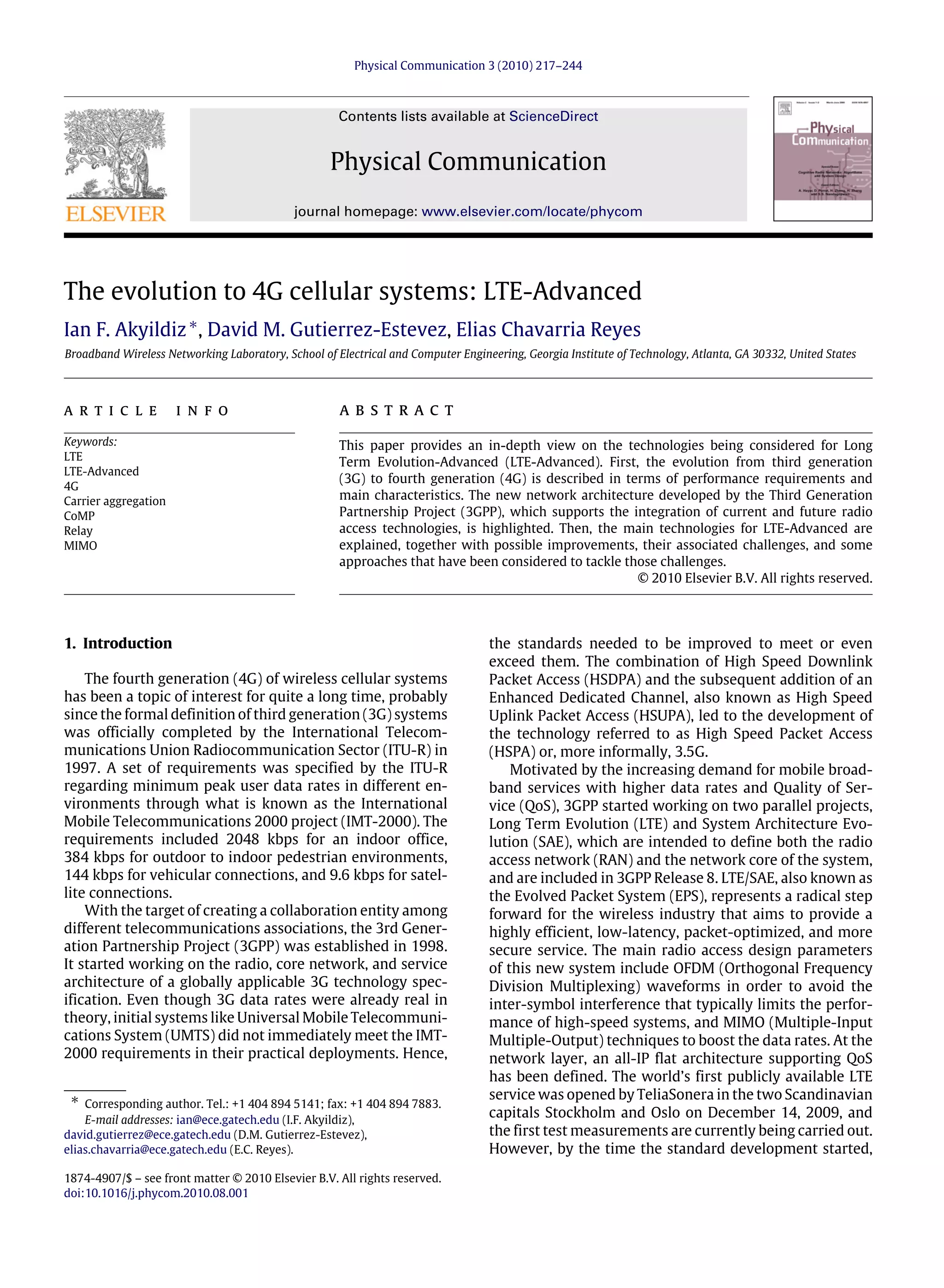
the spectrum as separate component carriers. In Fig. 4 we
illustrate the concept of Carrier aggregation in contiguous
bandwidth.
It may not be always possible for an operator to obtain
100 MHz of contiguous spectrum. For this reason, the use
2 Region 1: Europe, Africa, the Middle East west of the Persian
Gulf including Iraq, the former Soviet Union, and Mongolia. Region 2:
Americas, Greenland, and some of the eastern Pacific Islands. Region 3:
most of non-former-Soviet-Union Asia, east of and including Iran, and
most of Oceania.](https://image.slidesharecdn.com/georgiatech2010-150530225436-lva1-app6891/85/Georgia-tech-2010-4-320.jpg)
![I.F. Akyildiz et al. / Physical Communication 3 (2010) 217–244 221
Fig. 4. Carrier aggregation in contiguous bandwidth.
Fig. 5. Carrier aggregation in noncontiguous bandwidth, single band.
of noncontiguous carrier aggregation is also proposed. In
this case, the component carriers that are going to be
aggregated can be noncontiguous in the same spectrum
band or noncontiguous in different spectrum bands. In
either case, several challenges need to be addressed before
carrier aggregation can be successfully introduced, as
discussed later.
Fig. 5 illustrates the case of noncontiguous carrier
aggregation in the same band. The figure shows two LTE
devices using bandwidths of up to 20 MHz, coexisting
with an LTE-Advanced device that is using noncontiguous
aggregated bandwidth of up to 100 MHz.
Fig. 6 illustrates the case of noncontiguous carrier
aggregation in different bands, which is a scenario that
could result from the simultaneous use of the spectrum
bands mentioned at the beginning of this section. The
figure shows two LTE devices using bandwidths of up to
20 MHz, each one in a different spectrum band, coexisting
with an LTE-Advanced device that is using noncontiguous
aggregated bandwidth from different spectrum bands. The
bands that are used can be dedicated bands or shared
bands. In all the previous cases of carrier aggregation,
the number of UL and DL component carriers, as well as
their bandwidths, might be different. Even within a single
eNB, different LTE-Advanced UEs will be configured with
different numbers of CCs, according to their capabilities,
channel conditions, data rate requirements, and QoS
requirements.
Carrier aggregation not only helps to achieve higher
peak data rates, but could also help to achieve better
coverage for medium data rates. For medium data rates,
it allows the use of lower orders of modulation and lower
code rates, which would reduce the required link budget,
transmission power, and interference.
As an initial approach for carrier aggregation, 3GPP
specifies in [13,14] four deployment scenarios, which are
Fig. 6. Carrier aggregation in non-contiguous bandwidth, multiple bands.
shown in Table 2. These deployment scenarios cover both
contiguous and non-contiguous carrier aggregation for
single and multiple spectrum bands using time division
duplexing (TDD) and frequency division duplexing (FDD)
schemes.
3.1.1. Control channels
In order to utilize the available spectrum, devices must
be able to access the control channels in the downlink
and uplink frames (in addition to other reference sig-
nals). Hence, to keep backward compatibility with LTE
devices, each component carrier must maintain its own
control channels. On the other hand, if a service provider
wants to support only LTE-Advanced devices, the control
channels could be reduced from one set per component
carrier (of up to 20 MHz) to one set per group of aggre-
gated component carriers (of up to 100 MHz). The option
of enabling/disabling the control channels and reference
signals could allow a service provider to do a progressive
migration from LTE to LTE-Advanced, by controlling which
spectrum bands are accessible to LTE and which to LTE-
Advanced devices. For example, in [15], a layered control
signaling structure is proposed where the signaling struc-
ture depends on the assigned component carriers.
In terms of scheduling, the resource assignment infor-
mation (for DL and UL) can refer to resources within the
same CC in which it was sent, or to resources in another
CC. The first case is suitable for scenarios where the UE is
configured to receive resource assignment information at
each CC, and it can reliably receive it in each CC. On the
other hand, the second case is suitable for scenarios where
the UE is not configured to receive resource assignment in-
formation at each CC, e.g. when the bandwidth of the extra
CCs is small or is only available to LTE-Advanced devices.
The second case is also suitable for cases when it is not reli-
able to send resource assignment information in some CCs.
3.1.2. Multiple access scheme
For the downlink, the scheme chosen for multiple
access is to perform parallel transmission of transport
blocks (TBs) at each CC, based on OFDMA, as in LTE. In each
CC, a single TB (or two TBs in case of spatial multiplexing) is
transmitted; also, each CC manages its own HARQ process.
Furthermore, most of the upper-layer protocols of LTE are
reused, since the multi-carrier nature of the physical layer
is exposed as parallel paths up to the MAC layer. In this
way, most of the development and investment done for LTE
devices can be extended to LTE-Advanced.](https://image.slidesharecdn.com/georgiatech2010-150530225436-lva1-app6891/85/Georgia-tech-2010-5-320.jpg)
![222 I.F. Akyildiz et al. / Physical Communication 3 (2010) 217–244
Table 2
Primary LTE-Advanced deployment scenarios.
Scenario
no.
Description Transmission BWs of
LTE-A carriers
No. of LTE-A CCs Bands for LTE-A carriers Duplex
modes
A
Single-band contiguous spec.
alloc. @ 3.5 GHz band for FDD
UL: 40 MHz UL: Contiguos 2 × 20 MHz
CCs
3.5 GHz band FDD
DL: 80 MHz DL: Contiguos 4 × 20 MHz
CCs
B Single-band contiguous spec.
alloc. @ Band 40 for TDD
100 MHz Contiguous 5 × 20 MHz
CCs
Band 40 (3.5 GHz band) TDD
C
Multi-band non-contiguous
spec. alloc. @ Bands 1, 3 and 7
for FDD
UL: 40 MHz UL/DL: Non-contiguous
10 MHz CC@Band
1 + 10 MHz CC@Band
3 + 20 MHz CC@Band 7
Band 3 (1.8 GHz), Band 1
(2.1 GHz), Band 7
(2.6 GHz)
FDD
DL: 40 MHz
D Multi-band non-contiguous
spec. alloc. @ Bands 39, 34,
and 40 for TDD
90 MHz Non-contiguous 2 × 20 +
10 + 2 × 20 MHz CCs
Band 39 (1.8 GHz), Band
34 (2.1 GHz), Band 40
(2.3 GHz)
TDD
In the uplink, LTE uses DFT-precoded OFDM. For LTE-
Advanced there is one DFT per component carrier, support-
ing contiguous and frequency-non-contiguous resource
allocation on each CC. As for the downlink, the objective
is to reuse and extend most of what has already been de-
veloped for LTE [13].
3.1.3. Transceiver architecture
To utilize these wider spectrum bands, LTE-Advanced
devices must use wideband transceivers. As described
in [16], the two basic approaches for wideband communi-
cation transceivers are as follows.
• Multiple single-band transceivers: For n spectrum bands,
n transceivers are used, one for each spectrum band.
In this case, the transceivers work simultaneously,
allowing the use of all the spectrum bands simultane-
ously. As described at the beginning of Section 3, LTE-
Advanced is considering the use of six spectrum bands,
which would require at least six transceivers through
this scheme. This concept is feasible in the sense that
only requires the addition of parallel paths to process
each spectrum band, as in current multi-band devices.
However, this translates into an increase of the size
and cost of the mobile device. There exists a point at
which the transceivers join in the processing of the
signals. In Fig. 7, we show an example of a high-level
block diagram for a receiver [16], where the digital
signal processing is the point of union of the parallel
transceivers. The receiver has a single antenna, and sev-
eral RF branches. Each branch has an RF band pass fil-
ter for a specific spectrum band, an RF frontend, and
an analog-to-digital converter. In general, as the point
of union moves toward the antenna the number of ele-
ments reduces, which translates into a reduction of the
size and the cost of the device.
• Wideband transceiver: In this case, a single transceiver
processes all the spectrum bands of interest, and the fil-
tering of each individual spectrum band is usually done
in the digital domain. As described at the beginning of
Section 3, LTE-Advanced would process the spectrum
band from 450 MHz to 4.99 GHz through this scheme. In
Fig. 7. Multiple single-band receivers [16].
Fig. 8. Wideband receiver [16].
Fig. 8, we show an example of a wideband receiver high-
level block diagram [16]. It is composed of an RF band-
pass filter, RF frontend, analog-to-digital converter, and
digital signal processing blocks. Due to the wideband
nature of this type of transceivers, most of the RF com-
ponents used need to be wideband. Since the RF signal is
digitally filtered, very high-speed, high-resolution, and
high-dynamic range linear analog-to-digital converters
(ADCs) are needed.
Based on these two general classifications, 3GPP further
specifies subclassifications of transceiver structures for
LTE-Advanced, which can be found in [13].
3.2. Spectrum sharing
Carrier/spectrum aggregation allows a service provider
to offer up to 100 MHz of bandwidth to its LTE-Adva-
nced clients by aggregating dedicated spectra in order
to increase performance. However, in certain scenarios,
sharing of the spectrum becomes another attractive option
to achieve this objective.](https://image.slidesharecdn.com/georgiatech2010-150530225436-lva1-app6891/85/Georgia-tech-2010-6-320.jpg)
![I.F. Akyildiz et al. / Physical Communication 3 (2010) 217–244 223
Fig. 9. Multi-RAT scenario.
Spectrum sharing could be done among radio access
technologies (RATs), even though it is not currently speci-
fied by 3GPP. A service provider may offer more than one
RAT to its users (e.g. LTE, HSPA, WiMAX) in a specific area.
The reason for this is that the different clients of a ser-
vice provider might use UEs that support different RATs.
Hence, to provide coverage to all users, different RATs are
deployed. It can also occur that specific UE supports sev-
eral RATs. This gives the operator the flexibility of decid-
ing to which RAT(s) the UE should attach to maximize
spectrum utilization while providing the required QoS. In
this case, the requirements in terms of spectrum resources
will vary spatially and temporally for each RAT. This vari-
ation/diversity can be exploited in order to flexibly assign
resources to the RATs that require them at each time and
location.
In Fig. 9, each base station/eNB (they could be co-
located), will manage the spectrum that is currently
assigned to its RAT to serve its users, using a local radio
resource management (RRM). At an upper layer, a joint
RRM (JRRM) will be in charge of managing the sharing of
spectrum between both RATs. The level of granularity at
which the local RRM (which contains the scheduler) will
work will usually be smaller than the JRRM (e.g. LTE and
LTE-Advanced can define scheduling decisions each mil-
lisecond, so the JRRM could work in seconds or minutes
granularity). For example, in [17], a fuzzy-neural method-
ology framework for JRRM treatment is proposed, consid-
ering UMTS, GERAN, and WLAN, where one of the RATs
must be selected. Even though this type of sharing could
occur not only in LTE-Advanced, LTE-Advanced adds a new
level of complexity/degree of freedom by allowing the use
of carrier aggregation. Hence, the LTE-Advanced network
could borrow spectrum (contiguous or non-contiguous)
from other RATs and use it for carrier aggregation. This
will allow more flexibility in terms of the amount of spec-
trum that is assigned among RATs, potentially increasing
the performance in each one. The JRRM and local RRM will
work in a hierarchical way, where the spectrum that is
managed by the local RRM will depend on the assignments
done by the JRRM, which will depend on feedback infor-
mation coming from the local RRM and external policies,
as Fig. 10 shows.
The advantage of having a hierarchical RRM is that it al-
lows the lower-level entities in the hierarchy to perform
and communicate the RRM decisions faster and with less
overhead than in a scheme that only depends on a cen-
tral RRM entity. However, in cases of low network load
or low number of local RRM entities, the JRRM use can
be avoided if the local RRMs are available to manage the
Fig. 10. Joint RRM and local RRM.
load effectively by themselves (probably exchanging infor-
mation/measurements directly between them). This is the
case of LTE and LTE-Advanced, where the X2 interface in-
terconnects the different eNBs for coordination purposes,
without a specific central JRRM. It has been suggested that
the use of a central entity (JRRM) is only required and
used when the local RRM entities are not able to further
fulfill the network and user requirements [18]. [18] also
analyzes the advantages and disadvantages of centralized
and distributed admission control, scheduling and interfer-
ence management. In general, distributed approaches are
favored since they enable low delay, lower signaling, and
lower cost, even though they risk losing some gains com-
pared to their centralized counterparts. It has also been
proposed to assign a greater part of the RRM decisions to
the UE [19]; however, this approach requires more compu-
tation and power consumption from the UE (in addition to
information from the RAN and core network).
In addition to spectrum sharing among RATs, spectrum
sharing among service providers is also possible. This
concept is supported by 3GPP [20,21], and it is called
‘‘network sharing’’, since it also refers to the sharing of
elements at the RAN and core networks. An LTE/LTE-
Advanced UE must be able to decode the list of operators
sharing a cell, which is broadcasted by the eNB. Once the
UE selects a specific operator, the shared eNB forwards all
data to the core network of the selected operator. Beyond
this initial operator selection, the presence of network and
spectrum sharing is transparent from a UE perspective.
When the available spectrum is limited (either in the
low-frequency or high-frequency bands—with their intrin-
sic advantages and disadvantages), service providers may
need to share a spectrum band. By enforcing this, the reg-
ulator increases the pool of the spectrum that can be used
or aggregated by each service provider, without assigning
spectrum exclusively to one of the service providers. In this
way, no service provider will have the advantage of being
the exclusive owner of more spectrum than other service
providers. This is a feasible scenario in cases of scarce spec-
trum availability.
Spectrum and network sharing can also be catalysts
for the introduction of LTE/LTE-Advanced. Since the in-
vestment required for an LTE/LTE-Advanced deployment is
high, network sharing allows operators to reduce the ini-
tial investment that each one must do. As the number of
LTE/LTE-Advanced UEs increases, each operator can later
decide whether to keep the shared structure or deploy its
own LTE/LTE-Advanced network. For example, in low UE
density areas, the operators may favor keeping the shared](https://image.slidesharecdn.com/georgiatech2010-150530225436-lva1-app6891/85/Georgia-tech-2010-7-320.jpg)
![224 I.F. Akyildiz et al. / Physical Communication 3 (2010) 217–244
(a) Scenario 1. (b) Scenario 2.
Fig. 11. Spectrum sharing scenarios.
scheme, while in high UE density areas they may favor a
non-shared scheme.
In Fig. 11(a), three operators have their own dedicated
spectrum, and at the same time they share a spectrum
band. In this case, LTE-Advanced could take advantage by
using non-contiguous carrier aggregation (either on the
same or different spectrum bands). In Fig. 11(b), the spec-
trum is shared only between operators that are adjacent to
the shared spectrum; in this way non-contiguous carrier
aggregation is avoided which results in reduced complex-
ity but also reduced flexibility. Effective ways to achieve
spectrum sharing between several operators within the
same spectrum band are required to make this type of sce-
nario feasible, taking into account the performance and re-
quirements of LTE-Advanced.
In either case, or any other scenario, an entity (or
entities) will be in charge of coordinating and managing
the spectrum sharing between the different operators, as
shown in Fig. 12. The speed at which the spectrum is
dynamically shared between operators will be slower than
for JRRM and Local RRM.
The flexibility provided by the spectrum sharing be-
tween service providers gives an additional degree of free-
dom to the schedulers, allowing the realization of joint
scheduling and RRM between service providers. These sce-
narios of spectrum sharing require further investigation
in terms of adaptations at the core network and how
they can be implemented, taking into account coordination
between service providers. In addition, optimizing the al-
location of users in the shared bands and analyzing the
achievable gains through spectrum sharing must be further
investigated.
Some sharing scenarios, similar to the ones mentioned,
have been initially studied. In [20], general scenarios for
multi-operator network sharing are identified by 3GPP.
In [22], some of the possible dynamic sharing scenarios for
FDD and TDD spectrum sharing are presented, while [23]
proposes cooperation mechanisms for intra-system and
inter-system interworking, taking into account radio re-
source management (RRM) with spectrum aggregation in
the context of IMT-Advanced.
Another possible scenario for spectrum sharing is when
the eNB (a primary network according to the terminology
of cognitive radio networks) is not utilizing its entire
available spectrum band and decides to lease part of
this spectrum to a secondary network operator (e.g. a
cognitive radio network), with the objective of maximizing
its profit. This scenario can be further extended to include
coordination in a cooperative and non-cooperative way
between several primary networks and several secondary
networks. The non-cooperative case has already been
examined in the research community, assuming that the
primary network provides no support for the cognitive
network. However, for mobile wireless networks it may
be valid to assume some type of support for the cognitive
network.
Even though cognitive radio networks (CRNs) [24] have
become an area of extensive research in recent years, there
is still a need for clear deployment scenarios, requirements,
and constraints, where the benefits of using CRNs clearly
outweighs all the complexity related to deploying, man-
aging, and integrating the cognitive radio network with
the primary network environment (at both the radio ac-
cess network and the core network). IEEE 802.22 aims to
use cognitive radio networks, but focused on the TV fre-
quency spectrum. Therefore, there is still a lack of stan-
dardization for non-TV spectrum frequencies, which must
be addressed in order to increase the commercial imple-
mentations of cognitive radio networks.
3.3. Research challenges
The use of wider bandwidths, multiple spectrum bands,
and spectrum sharing introduces new challenges in terms
of transceiver, signal processing, resource management,
and error control mechanism design, among others.
3.3.1. Transceiver design
The design of wideband transceivers will be affected by
several factors [16], such as the following.
• Frequency-dependent path loss: As higher frequencies
are used, the path loss increases nonlinearly.
• Doppler frequency and spectrum: At higher frequencies,
the Doppler effects affect the signals more severely,
which would require faster adaptation algorithms,
increasing the overhead.
• Effective noise power: As the bandwidth increases, the
effective noise increases as well.
• Receiver input signal: Using a wider bandwidth trans-
lates into receiving more undesired signals from other
services (e.g. broadcast and radar signals). So, issues
such as image rejection, reciprocal mixing have to be
considered.
• Nonlinearities in analogue receiver components: Dis-
tortion and intermodulation create additional signals
under overload conditions, which can affect the demod-
ulation process.
• Reciprocal mixing: When undesired signals mix with the
oscillator noise, additional noise is introduced into the
receiver, resulting in an additional noise figure.
• Receiver performance: The performance of the receiver
will be limited by all the previous listed elements.](https://image.slidesharecdn.com/georgiatech2010-150530225436-lva1-app6891/85/Georgia-tech-2010-8-320.jpg)
![I.F. Akyildiz et al. / Physical Communication 3 (2010) 217–244 225
Fig. 12. Inter-operator RRM.
• Maximum input signal: The receiver has to have a suffi-
cient dynamic range to avoid overload conditions.
• Sampling frequency: Sampling the entire spectrum from
the lowest to highest frequency would represent an ex-
tremely high sampling frequency.
• ADC dynamic range and output data rate: With the mod-
els described in [16], a resolution of 21–24 bits is needed
with dynamic range of 120–130 dB. Combining this re-
quirement with the previous one translates into pro-
cessing rates far beyond what is currently feasible. This
also translates into high power consumption which
could not be used in UE.
These elements, among others, will determine the de-
sign requirements for the RF components, ADCs, and the
signal processing to be done in LTE-Advanced devices.
According to [16], the existing technologies cannot address
all the limitations and requirements previously listed for
the design of a wideband transceiver, and this suggests
that the only feasible technical solution is the one shown
in Fig. 7. Nevertheless, due to the attractiveness in terms
of potential complexity, number of elements, and power
consumption reduction of wideband receivers, some ap-
proaches have been explored for their design.
For example, in [25], the use of bandpass sampling [26]
is proposed for receiving signals from multiple bands with-
out the need of a full transceiver for each band. The ad-
vantage of this technique is that the sampling frequency
is proportional to the signal bandwidth and not to the RF
carrier. Their focus is to calculate a single parameter, the
sampling frequency, in order to process all bands. How-
ever, this calculation is subject to constraints that could
increase the sampling frequency considerably. Also, it re-
quires the ADC to be able to accommodate the RF carrier,
even if the sampling frequency is lower. To overcome these
constraints, [27] proposes the use of a common intermedi-
ate frequency stage with a common oscillator and common
bandpass filter, reducing the number of required elements
after LNA to half by sharing components, and allowing ad-
justable receiver bandwidth. However, in both of the pre-
vious approaches, only the aggregation of two spectrum
bands has been studied.
A more comprehensive study in the design of multiple
single-band transceivers in which the ‘‘union point’’ is as
close as possible to the antenna is still required. In addi-
tion, new approaches for designing wideband transceivers
(for more than two spectrum bands) that could be imple-
mented with current technologies, or at least lower the
requirements for the transceiver components, must be
studied. In this way, the evolution needed in current tech-
nologies in order to satisfy the requirements could be low-
ered. The design of elements such as wideband antenna,
LNA, and RF components must also be investigated, taking
into account the requirements of LTE-Advanced.
As we have described, the level of complexity, power
consumption, and size required to achieve the highest
carrier aggregation modes is high. Therefore, enabling
high-end carrier aggregation modes may be unfeasible for
mobile phones. However, LTE-Advanced is not only target-
ing mobile phones, but also laptops/netbooks and other
types of customer-premises equipment (CPE). These de-
vices do not have the same restrictions as mobile phones,
which makes them more suitable for high-end carrier ag-
gregation modes, as described in [14].
3.3.2. Increased FFT size
LTE utilizes up to 20 MHz bandwidth, for which
it requires a 2048-point FFT [28]. In the case of LTE-
Advanced, a bandwidth of 100 MHz requires an FFT of
increased size. If we follow the trend in LTE of FFT size
versus bandwidth, for 100 MHz, an FFT size of 10 240
would be needed. This will directly affect the memory size,
and the base-band processing power requirement.
3.3.3. Resource management
The option of using more than one spectrum band (ei-
ther dedicated or shared) is immediately followed by the
decision of how many bands and which bands should
be used in order to satisfy the different constraints and
requirements (delay, jitter, rate, interference, power con-
sumption, mobility, reliability, subscription plan, cove-
rage—path loss, fading, Doppler effect, etc.). As explored
in [29], the lower-frequency bands are better suited
for longer-range, higher-mobility and lower-capacity sys-
tems, while higher-frequency bands are better suited for
shorter-range, lower-mobility, and higher-capacity sys-
tems. This decision should also take into account the ca-
pabilities of the UE: multiple band support, minimum and
maximum distance between component carriers, and min-
imum and maximum number of frequency bands that can
aggregate. For example, [30] takes into account the num-
ber of CCs in which each UE can be scheduled in order to
improve the performance of a proportional fair scheduling
algorithm.](https://image.slidesharecdn.com/georgiatech2010-150530225436-lva1-app6891/85/Georgia-tech-2010-9-320.jpg)
![226 I.F. Akyildiz et al. / Physical Communication 3 (2010) 217–244
Fig. 13. LTE and LTE-Advanced carrier aggregation scenario.
Service providers will choose different spectrum and
network sharing schemes according to their objectives
and agreements. Hence, efficient RRM strategies for each
scheme are required, flexible enough to support evolution
from each scheme to another. The efficiency and flexibility
of the RRM will be a key point in the success of spectrum
sharing for LTE and LTE-Advanced.
At the radio access network level, the existing pro-
cesses must be re-examined. The processes of admission
control, congestion control, cell selection and re-selection,
handover, and scheduling (of users and data across bands)
have to be re-examined and adapted to take into account
the multi-band nature of LTE-Advanced. For example, con-
sider a scenario where a group of the component carri-
ers in use by the UE is no longer available. A new set of
component carriers must be assigned to the UE in order to
continue providing the services that the UE required. This
situation could trigger any of the processes mentioned
before.
Another possible scenario is the one depicted in Fig. 13.
The LTE-Advanced UE is within the transmission range
of an LTE-Advanced eNB and an LTE eNB. The UE has
the flexibility of using the spectrum band of the LTE eNB
and the extra bands provided through the LTE-Advanced
eNB. In this way, the ‘‘base band’’ (utilized for LTE UEs
within the LTE-Advanced eNB coverage) can be prioritized
for LTE UEs. This scenario of coordinated transmission
from multiple eNBs is possible and enhanced through
the MIMO and CoMP schemes available in LTE-Advanced,
which will be discussed in the following sections. In this
scenario, the radio resource management (RRM) processes
and algorithms can be enhanced to achieve the highest
resource utilization possible.
Some solutions have already been proposed for the
adaptation of the processes mentioned before. In [31],
the idea of a multi-band scheduler is explored in a sce-
nario where spectrum sharing is utilized and a second
scenario where single-band relays are utilized to extend
coverage. The multi-band scheduler acts as a new layer
in the protocol stack, controlling independent schedulers
for each band. It also supports user context transfer from
one band to another when the first band is no longer
available. Regarding the implementation of a multi-band
scheduler, [32] explores the user allocation over two fre-
quency bands based on an HSDPA network and a subop-
timal solution. However, user distribution, mobility, QoS
requirements, multi-radio UE, and multi-operator scenar-
ios are left as future work. In terms of performance, [33]
analyzed the performance of LTE-Advanced spectrum ag-
gregation over two frequency bands by considering two
different types of scheduler, and three different traffic
models (full buffer, finite buffer, and burst traffic). How-
ever, the scheduling only solves the resource allocation
up to a capacity limit; when the demand is increased,
queues will eventually start to overflow, and admission
control, congestion control, and handover functionality are
required.
3.3.4. Retransmission control
LTE uses a combination of ARQ (at the RLC layer) and
hybrid ARQ (at the MAC layer) in order to achieve the
low error probability required to achieve 100 Mbps. Both
methods complement each other to avoid excessive over-
head while achieving high throughput, specially taking
into account the relation between the error probability and
throughput in TCP.
In LTE-Advanced, data rates of 100 Mbps are expected
in scenarios of high mobility and 1 Gbps in scenarios of
low mobility. Also, shorter delays are expected in LTE-
Advanced. In order to achieve these high data rates and
small delay, the interaction of ARQ and hybrid ARQ must be
revisited to examine their current maximum performance
and analyze any adaptations required to achieve the
expected data rates and delay targets.
Some approaches to improve the ARQ/hybrid-ARQ in-
teraction have been proposed. In [21], a shorter transmis-
sion time interval (TTI) is proposed where the hybrid-ARQ
control information is transmitted each TTI, while the rest
of the control information is transmitted each two or three
TTIs, in order to reduce the transmission delay. In [34],
a global outer ARQ in a combination of hybrid ARQ for
each component carrier is proposed to reduce the switch-
ing delay when the UE needs to switch from one compo-
nent carrier to another. In addition, allowing the transfer of
HARQ information related to one component carrier to an-
other when this type of switching is required is proposed.
However, deeper understanding and analysis of the per-
formance achievable through carrier aggregation with the
current ARQ/hybrid-ARQ mechanism must be achieved in
order to propose new improved mechanisms.
3.3.5. Other aspects
Radio parameters, such as the number of carriers that
are needed as guard bands between contiguous compo-
nent carriers, must be optimized to achieve high utiliza-
tion of the spectrum without degrading the performance.
In [35], an initial investigation of the minimum spectrum
distance (carrier guard band) between component carriers
in contiguous spectrum bands was done.
Even though 3GPP’s initial deployment scenarios con-
sider the use of up to five component carriers and up to
three spectrum bands, it is reasonable to expect that more
scenarios will be required and investigated.
4. Enhanced MIMO
Multiple-Input Multiple-Output (MIMO) is a key tech-
nique in any modern cellular system that refers to the
use of multiple antennas at both the transmitter and re-
ceiver sides. Base stations and terminals are therefore](https://image.slidesharecdn.com/georgiatech2010-150530225436-lva1-app6891/85/Georgia-tech-2010-10-320.jpg)
![228 I.F. Akyildiz et al. / Physical Communication 3 (2010) 217–244
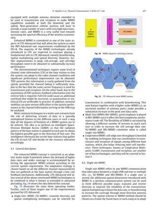
Fig. 16. Advanced precoding concept.
continuously to the spatial properties of the channel with
high spectral efficiency.
The single-site MIMO design currently under investiga-
tion for LTE-Advanced considers a substantial increase in
the number of transmission layers in both the uplink and
the downlink to achieve higher peak rates. However, this
measure entails two drawbacks. Firstly, the gains due to
additional diversity with such high-order configurations
become much smaller. Secondly, the spatial multiplexing
of a large number of transmission layers to a single user
may only be feasible if the radio conditions (i.e. SINRs) are
extremely favorable, which is unlikely to be found outside
very small cells, indoor scenarios or the proximities of an
eNB.
A more relevant technique aimed at increasing the wide
range of the data rates (i.e. coverage) is beamforming.
New technologies considered for LTE-Advanced include
improved support for beamforming as a tool to increase
the SINR at the receiver and employ some kind of spatial
multiplexing or diversity within the beam. An excessive
overhead may result if, as done in LTE, codebook-based
beamforming with cell-specific reference signals is em-
ployed with a large number of antennas. Therefore, ex-
tended UE-specific reference signals need to be considered
for LTE-Advanced.
4.2.1. Advanced precoding
Under the concept of advanced precoding, a novel
combination of single-user beamforming with spatial
multiplexing and spatial diversity as well as multi-user
beamforming is meant. Fig. 16 depicts an example of
this technology where two beamformed users are served
with multiplexing and diversity, respectively. As has been
pointed out before, the sole idea of increasing the number
of transmission layers or the diversity order does not
produce enough performance gain to compensate the
complexity increase. Besides, a more relevant target rather
than further increasing the peak rates is to improve
the range of the data rates and that is the reason why
beamforming is the base element of these new techniques.
Single-user or multi-user beamforming can be com-
bined with spatial multiplexing and diversity in order to
simultaneously improve the range of the transmission and
either obtain higher data rates (multiplexing) or a higher
reliability (diversity). These diverse techniques share the
requirement of multiple antenna elements but differ in
the antenna element spacing necessary for the different
schemes to work.
On the one hand, beamforming is able to provide high
directional gain and reduce the interference from other di-
rections provided that the MIMO channels are highly cor-
related. This implies that, under the beamforming mode
of operation, the antenna spacing must be small. A com-
mon distance used for these purposes is a half wavelength.
On the other hand, both spatial diversity (e.g. STBC) and
spatial multiplexing techniques (e.g. V-BLAST) require the
antenna spacing to be large enough (usually of several
wavelengths) that the correlation among the MIMO chan-
nels is low and the distribution of their corresponding fad-
ings can be considered as independent. Only in that way is
the former technique able to combat channel fading, and
the latter achieves a linear capacity growth with the num-
ber of antennas. Possible solutions for the antenna spacing
problem have been published in the last few years. Some
of the proposed ideas in the literature are the following.
• Smart antenna arrays [36]: the base stations are equi-
pped with more than one antenna array separated by
several wavelengths while the antenna elements within
the arrays are separated only by a half wavelength; mo-
bile stations are supposed to be equipped with multiple
antennas as well. This scheme simultaneously provides
the high-correlation and low-correlation scenarios nec-
essary for the different techniques. Both the spectrum
efficiency and the BER performance are significantly
improved. However, this solution presents the disad-
vantage of needing a large number of antennas at the
base station.
• Antenna grouping [37]: beamforming weight vectors are
calculated at the receiver and sent back to the transmit-
ter. The performance will not deteriorate with highly
correlated channels since those are grouped and beam-
forming is applied on them while spatial multiplexing
is applied among the different groups, which tend to be
less correlated.
• Antenna cross-polarization [38]: an antenna is said to
be cross-polarized if it can transmit electromagnetic
waves with orthogonal polarization modes. Two spa-
tially separated antennas can be replaced by a cross-
polarized single antenna element emulating two MIMO
channels. It was shown that in the presence of high
spatial fading correlation this scheme can yield an im-
proved multiplexing gain. Therefore, multiple anten-
nas should be spaced only a half wavelength apart and
beamforming can be also applied. Cross-polarization is
currently the solution that is being utilized in the LTE-
Advanced standardization process.
LTE Release 9 already incorporates a single-user dual-
layer beamforming functionality that extends the single-
user beamforming of LTE to support spatial multiplexing.
It is also based on UE-specific reference signals and it
supports fast rank adaptation (i.e., the number of data
streams that are to be sent at the same time may vary from
one time slot to another) without the need for higher layer
signaling. These new enhanced features and capabilities
should be backward compatible with LTE Release 8 and
forward compatible with LTE Release 10 (LTE-Advanced).
Advanced precoding is the natural extension of this feature
to MU-MIMO and is currently under discussion.](https://image.slidesharecdn.com/georgiatech2010-150530225436-lva1-app6891/85/Georgia-tech-2010-12-320.jpg)
![I.F. Akyildiz et al. / Physical Communication 3 (2010) 217–244 229
Fig. 17. Grid of beams approach: spatial beams (top) and concept
illustration (bottom).
4.3. Downlink MIMO transmission
The characteristics of the downlink single-site MIMO
transmission are summarized in this section. The num-
ber of antennas in both transmission and reception is
increased: a 4 × 4 MIMO antenna configuration would
become the baseline while a maximum configuration of
8 × 8 MIMO could be set to achieve high peak rates.
Operation in both open-loop and closed-loop modes is
possible in combination with diversity and spatial multi-
plexing, i.e. feedback information may or may not be sent
back by the UE depending on the radio conditions and the
UE mobility. Closed-loop transmit diversity is a new fea-
ture of LTE-Advanced intended for scenarios with low mo-
bility and bad channel quality.
In order to minimize intra-cell interference, MU-MIMO
will be based on one or two of the following approaches:
a set of fixed beams, a user-specific beam technique, or a
combination of both. Solutions under consideration for the
two cases are briefly described in the following, although
this is still an open issue.
Grid-of-Beams (GoB) is a concept widely accepted for
the fixed-beam approach [39] and is depicted in Fig. 17. A
limited set of possible precoding vectors is associated one-
to-one with the set of beams so that radio resources in time
and frequency are shared among different users without
severe interference. The system can operate in both open-
loop and closed-loop modes by using UE feedback in the
former case and deriving the selected beam from the
uplink in the latter one. This scheme is suitable for high
mobility and requires pilots dedicated to each beam to
determine the one with the highest received power.
User-specific beamforming is an approach that does not
employ predefined procoder sets in order to provide the
base station with more freedom to control or nearly null
intra-cell interference. Instead, the base station may freely
adjust downlink transmission weights depending on the
channel conditions. These techniques are known as non-
codebook-based techniques. The idea of LTE-Advanced is
to extend the single-user dedicated beamforming concept
of LTE to multiple users (i.e. SDMA) while supporting
spatial multiplexing, and transmit diversity at the same
time. The most common precoding technique for this case
is zero-forcing (ZF), a suboptimal strategy that can easily
be implemented in practice by choosing the weight vectors
as the pseudo-inverse of the composite channel matrix of
the users to avoid interference among user streams [40,
41]. Dirty Paper Coding (DPC) [42] is another multi-user
precoding strategy based on interference pre-subtraction
that achieves optimal performance in the downlink but
suffers from high computational burden when the number
of users is large. Precoding based on maximization of
signal-to-leakage ratio [43] is another candidate approach
to design the beamforming vectors that does not impose a
restriction on the number of available transmit antennas
and so is Block Diagonalization (BD) [44]. Any of these
techniques could be used to implement user-specific
beamforming.
These kind of non-codebook-based precoding schemes
require the terminal to make an estimate of the overall
beamformed channel, as LTE already established. This is
enabled through the inclusion of UE-specific reference
signals that are equally precoded before transmission as
the user data so that the terminal is capable of estimating
the overall beamformed channel. Additionally, the number
of transmit antennas used for non-codebook transmission
is not constrained by the number of available cell-specific
reference signals which must not interfere with each other.
LTE-Advanced needs to specify new reference signals in
addition to the common reference signals (CRS) defined in
Release 8 of LTE. Besides in-band channel estimation, other
measurements need to be considered in order to enable
adaptive multi-antenna transmission. Two additional ref-
erence signals have been specified by 3GPP. They are de-
picted in Fig. 18 and explained in the following.
• Channel state information reference signal (CSI-RS):
this is used for channel sounding, i.e. estimation of
the channel quality in different frequencies to those
assigned to the specific UE. The signals are located in
a sparse grid and require low overhead.
• UE-specific demodulation reference signal (DM-RS):
this reference signal is precoded in the same way as the
data when non-codebook-based precoding is applied.
The grid pattern should be extended from the dual
stream beamforming mode defined in Release 9 where
Code Division Multiplexing (CDM) between the RS of
two layers is utilized.
4.4. Uplink MIMO transmission
The LTE-Advanced uplink should provide significant
improvements over LTE Release 8 in cell-edge, cell average,
and peak data rates. The favorable characteristics of
Single-Carrier Frequency Division Multiplex Access (SC-
FDMA) of LTE Release 8 have reassured LTE-Advanced to
keep the same access method, which basically consists
of an additional DFT precoding phase preceding the](https://image.slidesharecdn.com/georgiatech2010-150530225436-lva1-app6891/85/Georgia-tech-2010-13-320.jpg)
![230 I.F. Akyildiz et al. / Physical Communication 3 (2010) 217–244
Fig. 18. CRS-based versus DM/CSI-based precoding.
conventional OFDMA. However, the inclusion of SU-MIMO
in combination with a higher-order MIMO is seen as one
of the key techniques to achieve significant technology
advancement. The baseline MIMO configuration for LTE-
Advanced is changed to 2 × 2 MIMO and a maximum
configuration of 4×4 MIMO should be available, enabling a
spatial multiplexing of up to four layers. This feature allows
a large increase in the peak spectrum efficiency, getting to
achieve 15 bits/s/Hz with 64-QAM [6].
Codebook-based precoding plays an essential role in the
uplink. Two main alternatives have been under discussion
in 3GPP: wideband (WB) precoding and frequency selec-
tive (FS) precoding. The former scheme applies the same
precoding vector on the whole frequency band while the
latter may select a different precoder on each resource
block. After multiple discussions, it has been agreed that
WB precoding is more suitable since FS does not provide
any gain over WB for an equal amount of feedback [45].
Codebooks are designed so that the cubic metric (CM), a
parameter defined as the cubic power of the signal of in-
terest compared to a reference signal, is kept low. The CM
is used for describing practical amplifier design. This way,
the peak-to-average power ratio (PAPR) is more empha-
sized in the uplink and the favorable SC-FDMA properties
are maintained [46]. Dynamic rank adaptation [47] is also
introduced in Release 10 to obtain further performance im-
provements.
Link Adaptation will be supported in addition to some
advanced receiver implementation such as Successive In-
terference Cancellation (SIC). Optional layer shifting (LS)
in combination with HARQ-ACK spatial bundling [46] has
also been proposed. In order to introduce additional spatial
diversity gain a transmit antenna switching (TAS) scheme
may be introduced where code symbols belonging to the
same stream are transmitted on different antennas on a
slot-by-slot basis. The required channel quality feedback
for multiple streams is therefore reduced since all the
spread data streams pass through similar channel condi-
tions. Fig. 19 shows a sample transmitter with a TAS for
two streams and four transmit antennas. Further, instead
of associating one HARQ process per layer, two layers could
share a single HARQ process by generating a single ACK for
both layers, which would be true only when both transport
blocks have been decoded properly.
Different transmit diversity schemes supporting SU-
MIMO are being studied for the uplink. The challenge is to
find suitable transmission schemes for all uplink channels
maintaining backwards compatibility and low CM proper-
ties. Both open-loop and closed-loop schemes have been
proposed. Open-loop schemes differentiate between the
Physical Uplink Control Channel (PUCCH) and the Phys-
ical Uplink Shared Channel (PUSCH) since it seems un-
feasible to find an optimal scheme for both channels.
Many contributions have centered their attention on this
topic [48–52]. For PUCCH, Orthogonal Resource Diversity
(ORT) or Precoder Switching Diversity (PVD) have been
proposed, while Space–Time Block Coding (STBC) or Space-
Frequency Block Coding (SFBC) are candidate schemes for
PUSCH. Further, an alternative slow closed-loop precoding
exploiting spatial correlation among transmit antennas has
been proposed in [52].
As mentioned above, in the development of these
new technologies the backwards compatibility needs to
be taken into account. Support for legacy devices must
be granted at least on part of the component carriers.
Therefore, an additional complexity arises from the need
to keep multiple solutions and the achievable gains have
to be compared against this extra complexity.
4.5. Research challenges
There exist a number of research challenges related
to single-site MIMO that are currently being investigated.
New techniques enabling the above features should be
developed and at the same time compatibility with the
current standard and previous versions of it to ensure
backward compatibility must be taken into account.
4.5.1. Physical size limitation at the UE
The main challenge regarding the support for four an-
tennas at the UE is related to the physical space limitations.
As is well known, a reduced spatial separation between the
antennas of the same array can significantly decrease the
achievable MIMO gain, and this fact becomes a problem
when trying to accommodate a large number of antennas
with adequate spacing in a handset device. Furthermore,
if four to eight antennas are working in the same handset,
the power consumption might be too high to be absorbed
by a single power unit. Solutions to this problem have been
proposed in the literature. Among them we highlight the
following two approaches.
Fig. 19. TAS transmitter for two streams and four transmit antennas.](https://image.slidesharecdn.com/georgiatech2010-150530225436-lva1-app6891/85/Georgia-tech-2010-14-320.jpg)
![I.F. Akyildiz et al. / Physical Communication 3 (2010) 217–244 231
• Virtual MIMO communications [53]: virtual MIMO tech-
niques among UEs are a promising approach that could
be applied in both the uplink and the downlink. If the UE
needs to communicate with an eNB, it could look for UEs
in its vicinity to share the data with, and transmit the
data in one slot as if the multiple antennas were located
on the same MIMO device. An analog approach would
be followed for the downlink: knowing the UEs in the
surroundings of the targeted terminal, the base station
could deliver the data to all of them as if they were a
single device. The main issue regarding this technique
is to design a reliable and efficient inter-UE link (IL) tak-
ing into consideration the special features of both the
uplink and the downlink. Relaying strategies, IL spatial
re-use, radio access technologies, or location informa-
tion of the UEs at the eNBs are examples of issues that
would need to be studied.
• Antenna selection [54]: the mutual antenna coupling at
the UE due to close spacing can be also combated with
antenna selection schemes. These schemes may range
from hard detection, such as hybrid selection method
where only some of the antennas are active, to soft
detection methods, which apply a certain transforma-
tion to the received signals across all the antennas in
the RF domain. Studied soft selection methods include
so-called FFT-based selection and phase-shift-based se-
lection. Results show that soft selection methods out-
perform hard selection methods when the spacing is
larger or equal to one half wavelengths. Moreover, a
better performance in terms of spectral efficiency can
be achieved if a few more antennas than necessary are
placed and a phase-shift-based selection is applied.
4.5.2. Feedback design
The uplink feedback channel is a bottleneck for the
system performance in an FDD system. Many of the new
features included in LTE-Advanced require an increased
quantity of channel information, and very efficient feed-
back schemes are needed in terms of lower resource usage
and finer granularity of the CSI knowledge at the eNB.
In the context of single-site MIMO, the feedback scheme
must be defined taking into account that the use of up
to eight transmit antennas require an accurate channel
information which, at the same time, must maintain a
decent amount of overhead. MU-MIMO is greatly affected
by the feedback design since, in practice, inter-user
interference cannot be nulled out perfectly. Terminals
need to be aware of this interference when reporting the
channel quality indicator (CQI), but this is not always an
easy task. Regarding the uplink, efficient channel state as
well as precoding information feedback for closed-loop
operation need also be well designed. In this case, TDD
may have a slight advantage over FDD due to the channel
reciprocity.
The introduction of UE-specific beamforming poses
new challenges to optimize the feedback design as well.
Since there are no predefined codebooks, the feedback
should not be restricted to an index pointing to a precoding
matrix. Instead, methods to reliably and efficiently trans-
mit the channel information should be investigated. Here,
the compression method and source coding of the SINR
value play a major role and they should be designed in such
a way that an adaptive frequency resolution over the band-
width is allowed. Techniques that have been investigated
include the Wavelet Transform [55], where the UE adap-
tively provides high CQI resolution (i.e. a larger number
of bits) on good resource blocks and low resolution (i.e. a
smaller number of bits) on bad resource blocks, and Hier-
archical Feedback, probably the most relevant approach in
this field. With this technique, the channel quantization is
based on hierarchical codebooks that take advantage of the
channel slow fading, as the CSI is refined successively over
several feedback periods. They can be represented as hier-
archical trees [56] supporting multiple tree types.
All these feedback issues bring about the debate
whether more complex channel reporting methods are
necessary for LTE-Advanced. LTE Release 8 acquires CSI by
implicit reporting consisting of CQI, PMI (Precoding Ma-
trix Indicator) and RI (Rank Indicator). The three indicators
point to a recommended modulation and coding scheme,
precoding matrix and number of transmitted streams, re-
spectively. Explicit reporting, however, attempts to quan-
tify more precisely the characteristics of the propagation
channel such as the covariance matrix, complex chan-
nel impulse response, or eigenbeams. Moreover, schemes
combining both types of reporting have also been pro-
posed. In [57], an efficient feedback scheme that combines
‘short-term’ information (a quantized function of instanta-
neous channel) and ‘long- term’ information (channel co-
variance matrix) is used for the design of the scheduler and
beamformer to further improve performance.
4.5.3. Enhanced codebook-based transmission
In codebook-based precoding the transmit precoders
are chosen from predefined sets based on the feedback
received from the terminals. It is a GoB concept since the
antenna arrays are uniformly linear, and combined with
precoding they form directional beams. The support for
up to eight transmit antennas has a great impact in the
codebook design for closed-loop operation. The size of the
codebook is large, so the terminal will need to determine
the preferred precoding matrix index (PMI) among a
large number of them, and the required calculation and
processing will be very large. Therefore, there is an
important need for optimized codebooks to reduce the
computational burden and both intra-cell and inter-cell
interference.
Two relevant codebook-based approaches to further
reduce the inter-cell and intra-cell interference are known
as ‘‘best companion’’ and ‘‘worst companion’’ [58,59]. The
approaches are based on the idea that the UE will report
the best beam index for its serving cell plus the so-called
best-companion (or worst-companion) index (BCI and
WCI), i.e. the codebook index of a potential co-scheduled
interferer which maximizes (minimizes) the SINR at the
receiver output. Likewise, CQIs for the case that BCIs
(WCIs) are not used will be reported as well. Based on this
information, a user pairing based on BCI can be performed
by the eNB to reduce intra-cell interference. Beam
coordination can also help to reduce inter-cell interference
by using a centralized scheduling that accounts for the fact
that no interference from reported WCIs will occur.](https://image.slidesharecdn.com/georgiatech2010-150530225436-lva1-app6891/85/Georgia-tech-2010-15-320.jpg)
![232 I.F. Akyildiz et al. / Physical Communication 3 (2010) 217–244
5. Cooperative multipoint transmission and reception
for LTE-Advanced
Future cellular networks will have to simultaneously
provide a large number of different users with very high
data rates, and the capacity of the new radio access systems
needs to be increased. Traditionally, in cellular systems
each user is assigned to a base station on the basis of
criteria such as signal strength. At the terminal side, all
the signals coming from the rest of base stations in the
form of interference dramatically limit the performance.
The user also communicates with a single serving base
station while causing interference to the rest of them. Due
to the interference limitation of cellular systems, the task
of high data delivery cannot be accomplished by simply
increasing the signal power of the transmission. Each base
station processes in-cell users independently, and the rest
of the users are seen as inter-cell interference whose
transmission power would also be increased.
One strategy to reduce the performance-limiting inter-
ference is to reduce the inter-cell interference with the
help of cooperative transmission. Cooperative Multipoint
(CoMP) transmission and reception is a framework that
refers to a system where several geographically distributed
antenna nodes cooperate with the aim of improving the
performance of the users served in the common cooper-
ation area. It encompasses all required system designs to
achieve tight coordination for transmission and reception.
Cooperation among eNBs is characterized by the need of
an interconnection among the different nodes in the form
of very-high-speed dedicated links. Optical fiber, wired
backbone connection or even highly directional wireless
microwave links could be some feasible examples. These
low-latency links are essential for the success of the coop-
erative communication, although its design is a very chal-
lenging issue due to the large amount of data that may need
to be exchanged among the nodes. LTE-Advanced will use
the standardized interface X2 for these purposes.
CoMP in the context of LTE-Advanced involves several
possible coordinating schemes among the access points.
Coordinated beamforming/scheduling is a simpler ap-
proach where user data are transmitted only from a single
cell. Joint processing techniques, however, requires multi-
ple nodes to transmit user data to the UE. Two approaches
are being considered: joint transmission, which requires
multi-user linear precoding, and dynamic cell selection,
where data are transmitted from only one cell that is dy-
namically selected.
This section of the paper presents a broad overview
of the architectures, approaches, and main challenges
regarding CoMP in the context of LTE-Advanced. It is
necessary to mention that most of these ideas are currently
being studied and therefore may change throughout the
standardization process.
5.1. The CoMP architecture
Coordination among eNBs is a very promising technique
to reduce inter-cell interference in the network in both the
downlink and the uplink. CoMP is applied in the downlink
by performing a coordinated transmission from the base
station, whereas interference in the uplink can be reduced
by means of a coordinated reception in eNBs. Most of
the CoMP approaches share the requirement of needing
some scheduling information regarding the users at the
different base stations that must be shared among them.
This means that very-low-latency links are required so that
information can be exchanged between coordinated nodes
in the order of milliseconds.
Two kinds of architecture can be distinguished with re-
spect to the way this information is made available at the
different transmission points as described in [60]: central-
ized and distributed CoMP. Both types of architecture can
be combined with any of the different CoMP transmission
schemes that will be presented in Section 5.2, although the
degree of complexity to implement them may vary from
one scheme to the other.
5.1.1. Centralized architecture
In a centralized approach, a central entity is needed in
order to gather the channel information from all the UEs
in the area covered by the coordinating eNBs. This entity
is also in charge of performing user scheduling and signal
processing operations such as precoding. Furthermore,
tight time synchronization among eNBs is needed and user
data need to be available at all collaborating nodes. On
the downlink of FDD systems the UE needs to estimate
the channel and derive channel coherent or non-coherent
indicators (CSI/CQI) to feed back to the eNB. In TDD
systems, the channel information can be obtained by using
channel reciprocity.
Fig. 20 depicts the centralized framework for coordina-
tion among different base stations. In the case of FDD oper-
ation, terminals must first estimate the channel related to
the set of cooperating eNBs. The information is fed back to a
single cell, known as the anchor cell, which acts as the serv-
ing cell of the UE when coordination is being employed.
Once the information is gathered, each eNB forwards it to
the central entity that is in charge of deciding the schedul-
ing and the transmission parameters, and this new infor-
mation is sent back to the eNBs.
The main challenges of this architecture are related
to the new associated communication links between the
central entity and the eNBs. They must support very-low-
latency data transmissions and in addition communication
protocols for this information exchange must be designed.
5.1.2. Distributed architecture
A distributed architecture is another solution to per-
form coordination that alleviates the requirements of a
centralized approach. Based on the assumption that sched-
ulers in all eNBs are identical and channel information re-
garding the whole coordinating set can be available to all
cooperating nodes, inter-eNB communication links are no
longer necessary to perform cooperation. Thus, this archi-
tecture has the great advantage of minimizing the infras-
tructure and signaling protocol cost associated with these
links and the central processing unit, so conventional sys-
tems need not undergo major changes. Furthermore, the
radio feedback to several nodes could be achieved without
additional overhead.](https://image.slidesharecdn.com/georgiatech2010-150530225436-lva1-app6891/85/Georgia-tech-2010-16-320.jpg)
![I.F. Akyildiz et al. / Physical Communication 3 (2010) 217–244 233
Fig. 20. Centralized CoMP approach.
Fig. 21. Distributed CoMP approach.
The procedure that needs to be followed in a distributed
CoMP environment can be described as follows. The UE
estimates the channel from all the coordinating eNBs in
the very same way as in the centralized approach. The
estimates are then sent back to all cooperating eNBs and
the scheduling is independently performed in each of
them, as Fig. 21 shows. Since the schedulers are identically
designed, the same input parameters produce the same
output decisions and therefore the same UEs are selected in
the entire eNB cluster. Similarly, transmission parameters
are jointly selected according to a common design in the
different nodes.
This scheme presents some drawbacks. First, if different
eNBs do not perform cooperation via a wired backhaul, the
performance of the CoMP algorithms is less efficient. Fur-
thermore, an obstacle associated with distributed trans-
mission is the handling of errors on the different feedback
links. The same UE reports its channel conditions to all the
eNBs in the set but the wireless links to the different nodes
might be very different and the impact of these errors on
the system performance cannot be neglected. In [61], this
impact is analyzed, and enhancements to the robustness of
this approach are proposed. They propose both to decrease
the probability of a malfunction and to recover from it.
5.1.3. Mixed architectures
There are also some promising approaches that lie be-
tween the former extreme cases and can combine advan-
tages of both schemes. 3GPP is thinking of an approach that
suppresses the central unit but maintains the communi-
cation links among the different eNBs. The decisions are
jointly made by the connected eNBs transmitting almost
simultaneously due to the high speed of the backhaul link.
Another technique decouples the scheduling and precod-
ing process [62], the former being carried out at the central
entity while the latter is locally designed at each eNB. This
approach, called collaborative MIMO, reduces the amount
of information that has to be exchanged among the differ-
ent nodes.
5.2. The CoMP schemes
In this section, we outline the different possible CoMP
schemes that are envisioned in LTE-Advanced for both the
downlink and the uplink. Independently of whether the
architecture is a distributed or a centralized one, differ-
ent approaches with different levels of coordination exist.
Their requirements in terms of measurements, signaling,
and backhaul are different, where as usual the highest per-
formance achieving schemes require the highest system
complexity.
CoMP techniques are being studied for both the down-
link and the uplink transmission paths. In the downlink,
two main CoMP transmission techniques are envisioned:
cooperative scheduling/beamforming and joint process-
ing. Their main difference lies in the fact that in the for-
mer scheme it is only one eNB that transmits data to the
UE, although different eNBs may share control information.
In the latter scheme, many eNBs transmit data simultane-
ously to the same UE. In the uplink, however, only a coor-
dinated scheduling approach is envisioned.
In general, the cost of the CoMP mode is found only
beneficial to the cell-edge users where the perceived
Signal-to-Interference-and-Noise Ratio (SINR) is low. This
is because more system resources are allocated to a single
user during its operation. However, first simulation results
suggest that CoMP can be used to increase both the average
cell throughput and the cell-edge user throughput [63].
5.2.1. Downlink
(a) Coordinated scheduling/beamforming. Coordinated
scheduling/beamforming (CS/CB) is characterized by the
fact that each UE is served by a single cell known as the
‘‘anchor cell’’. However, precoding at each base station to
achieve beamforming may be coordinated to improve the
sum throughput and reduce interference. Fig. 22 depicts an
architectural example of this transmission scheme.
The feedback design should be enhanced to give sup-
port for this transmission strategy. The scheduler at each](https://image.slidesharecdn.com/georgiatech2010-150530225436-lva1-app6891/85/Georgia-tech-2010-17-320.jpg)
![234 I.F. Akyildiz et al. / Physical Communication 3 (2010) 217–244
Fig. 22. Coordinated scheduling/beamforming approach.
eNB makes its decisions independently but additional in-
formation about other user’s channel conditions is neces-
sary in order to perform a more optimal scheduling and
beamforming. In the example of Fig. 22, the CS/CB proce-
dure would entail the following operations.
• Two eNBs have determined a candidate set of UEs to
be attached to both eNBs on a semi-static basis. For co-
ordinated precoding and UE pairing, eNBs then request
the candidate UEs to feed back channel information for
CoMP mode operation.
• The UE must estimate the downlink channel quality of
both the anchor cell and the interfering eNB. At this
point, different reference signals for link adaptation
measurements and demodulation purposes should be
used. Common reference signals (CRS) specific at each
cell present the problem of ensuring orthogonality for
each of the coordinating eNBs, especially given the fact
that the set of participating points in CoMP may be dif-
ferent for each individual UE. Overhead is also a con-
cern since UEs close to the eNB may not benefit from
CoMP. UE-specific reference signals, called demod-
ulation reference signals (DM-RS) in LTE-Advanced,
overcome this problem and also enable precoding flex-
ibility by not constraining it with a codebook. However,
for link adaptation purposes, CRS measurements could
be more tolerable to channel estimation errors so cell-
specific reference signals for channel state information
(CSI-RS), in addition to DM-RS, help the scheme to prop-
erly work.
• The UE feeds back its channel information together with
the interfering channel to its anchor eNB. The same op-
eration is performed with the second UE.
• Precoding matrices based on throughput maximization
and fairness constraints and final UE selection/pairing
are obtained by each of the base stations and the trans-
mission is performed accordingly. The UEs may use the
above-mentioned reference signals to perform demod-
ulation and link adaptation.
The generalization of this procedure to a more real-
istic scenario with a larger number of base stations and
terminals is quite straightforward, although the accurate
measurements in multiple UEs, the feedback, and the
information exchange among eNBs still present some
challenges. Nevertheless, simulations so far have demon-
strated that CS/CB with improved feedback can deliver sig-
nificant gain to cell-edge users [64].
Fig. 23. Joint processing techniques: joint transmission (left) and
dynamic cell selection (right).
(b) Joint processing. In the category of joint processing (JP),
data intended for a particular UE are jointly transmitted
from multiple eNBs to improve the received signal
quality and cancel interference. The information theory
paradigm to be exploited is the following: if antennas are
uncorrelated, the number of independent communication
channels is the same as the product of transmitting and
receiving antennas. Different site location means inherent
low correlation; hence, even though this approximation
gives an upper bound for the system capacity, a high
potential gain may be achievable.
Two different methods are being studied for the JP
scheme: joint transmission and dynamic cell selection.
Although data are indeed transmitted from several sites,
the former scheme does it simultaneously while the latter
uses a fast cell selection approach and only one of them
transmits data at a time. This advanced pair of techniques
is particularly beneficial for cell-edge throughput and is
anticipated to be the dominant application of CoMP. Fig. 23
shows a simplified scheme of both techniques. In both
cases user data need to be shared among base stations so
a very fast link interconnecting them is required, although
the complexity of the signal processing is higher in the joint
transmission scheme.
The joint transmission scheme primarily considers that
the transmission points correspond to different cell sites
and a cluster of base stations must jointly decide on the
transmission scheme of a signal to the UE. Precoding in
this context must be applied using DM-RS among the
coordinating cells. There are several design considerations
that need to be studied in order to take the most advantage
of this technique. Two relevant ones are the serving
set determination and the coherent versus non-coherent
transmission approach.
• Serving set determination: the determination of the
serving eNBs (also called eNB cluster) can be performed
in different ways. Firstly, the eNBs forming the CoMP
cluster can be determined either by the network, the
UE [65], or adaptively between the UE and network [66].
Secondly, the cluster could be formed by a fixed set of
serving cells or by a flexible set. These two different
candidate approaches are described in the following.
If the serving set is a fixed one, the cells within the
cluster will always serve the target UE simultaneously.
An approach to implement this idea could be to employ
different frequency zones for users performing CoMP,
i.e. users at the cell-edge. The procedure would be
then simple: the UE is determined to be served with](https://image.slidesharecdn.com/georgiatech2010-150530225436-lva1-app6891/85/Georgia-tech-2010-18-320.jpg)
![I.F. Akyildiz et al. / Physical Communication 3 (2010) 217–244 235
CoMP mode or not depending on its SINR value before
the scheme is applied. If the decision is positive, the
UE will be scheduled to a preconfigured frequency
zone jointly scheduled with other CoMP UEs. At that
moment, all the cells within the cluster will serve the
UE simultaneously.
The problem with the above-described approach is
that forcing all the cells within the cluster to serve a
single UE may lead to a waste of resources since the
signal strength from some of the cluster’s eNBs might
be very weak. An example is a cluster of three eNBs
where the signal strength coming from eNBs 1 and 2
is much stronger than the one coming from 3. In other
words, H11 ≈ H21 ≫ H31. In this situation, the size
and elements of the CoMP cluster could be changed,
but flexible scheduling of the actual transmitting cells
within a specified cluster would be much easier to
implement. Additionally, the cluster setup might have
been statically or semi-statically established and a
change in its configuration could affect the other UEs.
The third base station would improve its resource
utilization by serving another UE closer to its position.
Although interference to UE 1 would appear, it would
not cause much throughput degradation due to its
remoteness.
• Coherent and non-coherent transmission: in terms of
ways to transmit and combine the signals, joint trans-
mission can be classified as coherent and non-coherent
transmission techniques. In coherent transmission, the
network obtains channel state information (CSI) from
all the cooperating cell sites. The phase of the transmit-
ted signal can be adjusted to the CSI in such a way that
the receiver is able to combine them at symbol level
coherently. While combining is an implementation is-
sue, it affects the signaling support design for the CoMP
downlink. This allows for an additional multi-cell ar-
ray gain besides the single-cell and multi-cell precoding
gains. Two possible implementations of coherent trans-
mission could be a different phase correction applied to
each cell or a global precoding matrix based on all the
CSI between cooperating cell sites and the intended UE
where each cell uses part of the global matrix as pre-
coder.
On the other hand, for non-coherent transmission the
network does not have information concerning the re-
lationship of the channels among the cooperating cells.
Under this situation, the received signals arriving at
the UE cannot be coherently combined. This is due to
the fact that cell-edge users calculate channel qual-
ity indicators (CQIs) and report them to their serving
cells without providing thus channel phase informa-
tion. This kind of scheme has been widely used for
single-user MIMO to simplify the system overhead and
backhaul capacity, although the gains are not as big as
with the coherent approach. Examples of implementa-
tions of this technique include SFBC, Cyclic Delay Diver-
sity (CDD) [67], or multi-user eigenmode transmission
(MET) scheduling [34]. Non-coherent combining can be
performed at soft-bit level after demodulation, analo-
gously to HARQ combining.
Fig. 24. Uplink CoMP scheme.
On the other hand, the dynamic cell selection approach
is a joint processing scheme where the transmission to the
intended UE only takes place from one point at a time.
This point must be drawn from the CoMP cooperating set
serving the same UE. The switching can be produced at
most on a subframe-by-subframe basis, thus allowing a dy-
namic change in the transmission point that is transparent
to the UE. The related radio resource management, packet
scheduling, and common channels are tasks always per-
formed by the serving cell. The fact that no more than one
eNB transmits at the same time implies that there is no
need for the eNBs to have a tight phase synchronization.
Hence, dynamic cell selection can be implemented with re-
laxed RF performance requirements, what makes it an ap-
propriate technique for HeNB networks.
5.2.2. Uplink
In the uplink the CoMP scheme, aimed at increasing
the cell-edge user throughput, implies the reception of the
signal transmitted by UEs at multiple and geographically
separated points, as Fig. 24 shows. These points are nothing
but the set of coordinating eNBs assigned to each UE.
Generally speaking, the terminal does not need to be
aware of the nodes that are receiving its signal and what
processing is carried out at these reception points. This
is all an implementation issue, so CoMP reception is
expected to have limited impact on the specifications,
and no major change in the radio interference should
be required. Nonetheless, scheduling decisions can be
coordinated among cells, and some specification impact
may be brought from this fact.
There are different schemes that can be used at mul-
tiple reception points to combine the received signals.
Maximum Ratio Combining (MRC), Minimum Mean Square
Error Combining (MMSEC), and Interference Rejection
Combining (IRC) are examples of techniques that extract
the transmitted information from the received signal.
Despite the above-mentioned considerations, it has
been noticed that there are some issues which may im-
pact the system performance and should be further inves-
tigated. In particular, the delay spread issue may limit the
benefits of CoMP since the signal could arrive at different
cells at dispersive time instants separated by a larger in-
terval than the normal cyclic prefix length, and this would
cause performance degradation [68]. Basically there are
two proposed approaches to combat this problem [69].](https://image.slidesharecdn.com/georgiatech2010-150530225436-lva1-app6891/85/Georgia-tech-2010-19-320.jpg)
![236 I.F. Akyildiz et al. / Physical Communication 3 (2010) 217–244
• Flexible cyclic prefix: the delay spread problem can be
solved by using an extended cyclic prefix that would
get rid of it. However, this solution also implies a high
overhead for the whole system that needs to be avoided
if high cell average throughput is also desired. UEs that
cause a large delay spread may be then scheduled in
the TTIs with extended cyclic prefix so that it can be
served by more than one cell; on the other hand, the
rest of the UEs can be scheduled in the TTIs with normal
cyclic prefix and no unnecessary throughput has to be
sacrificed.
• New timing advance (TA) adjustment: this method aims
at reducing the arriving time spread in CoMP cells by
adjusting the TA of the cell with minimum transmission
time delay (i.e. the closest cell) in the active CoMP set
so that the signal will not arrive at this cell’s receiver
earlier than expected.
The delay spread is a topic that should be effectively
solved with either one or both of the above approaches.
In any of the cases, uplink timing estimation at multiple
receiving cells is an open issue that needs to be further
investigated and enhanced.
5.3. Research challenges
Cooperative multipoint transmission and reception
comprises a promising spectrum of techniques that still
need to be further investigated. First simulations have
shown great potential and very promising results but there
are many issues that still remain open. Probably the most
relevant issue that still needs to be addressed is a thorough
evaluation of the practical performance versus complexity
trade-off since the feasibility of CoMP technology within
LTE-Advanced is still not clear. In fact, 3GPP has recently
decided that only coordination between the sectors of a
single site will be included in LTE Release 10 [70].
Some of the challenges have been already pointed out
along the description of the techniques. Here, a summary
of the most challenging issues is provided.
5.3.1. Channel estimation and feedback
An important concern regarding cooperative transmis-
sion is the support for multi-cell channel estimation that
must be provided at the UE. Since propagation losses vary
between cells and consequently the power of the reference
signal to be measured, channel estimation at the UE be-
comes more challenging.
A need also arises for enhanced feedback in FDD sys-
tems with minimal impact on the signaling overhead to
avoid both reducing the uplink capacity and increasing
the UE battery consumption. Feedback signalling is also
the key to a fast and flexible adaptation from single-site
to multiple-site MIMO in varying radio environments and
different network scenarios. The parameters which may
need to be acquired include coherent or non-coherent
channel information between the UE and eNBs antennas
as well as preferred precoding matrix indices and received
power from each of the coordinated points. In any case,
JP is more sensitive to feedback errors than CS/CB, and it
becomes difficult to ensure constructive addition of signals
from different cells at the receiver.
The requirements on TDD systems are somewhat differ-
ent from those for FDD. Since the channel reciprocity prop-
erty is used, the main problem is to understand how the
coherence time of the channel and the accuracy of the
channel estimation affect the different techniques. Ad-
ditionally, the quantization and feedback of the channel
information over the backhaul also needs to be indepen-
dently studied, as the problem definition is different from
the FDD feedback.
5.3.2. Backhaul aspects
As mentioned throughout this paper, a large amount
of data exchange between eNBs must be carried out over
the backhaul with the minimum possible latency. This calls
for very-high-speed communications links and efficient
communication protocols. The technologies and media
available for backhauling will have a strong impact on the
available rates and latencies so they have to be carefully
selected according to their cost/performance trade-off.
In addition, it is important to distinguish if the coopera-
tion is performed between sectors of the same eNB, requir-
ing no bandwidth backhauling, or between different sites.
Regarding the amount of data to be transmitted, the coop-
eration can be carried out only in the control plane (CS/CB)
or in the control and user plane (JP). The JP schemes are the
most challenging ones since channel information, schedul-
ing decisions, and precoding weights must be exchanged
over the backhaul. Besides, user data must be available at
each transmission point.
There exist different solutions in the literature that
have been proposed for alleviating backhaul requirements.
Serving only subsets of UEs with joint transmission [71]
or partitioning a cellular network into small subsystems
where these schemes can be applied locally [72] are some
examples. However, a clear configuration and coordination
policy for the serving sets are still to be decided.
5.3.3. Reference signal design
The main challenge regarding the design of reference
signals is to obtain the precise channel state information
that is required for CoMP among the cooperating eNBs. This
imposes requirements on the pilot design to enable such
estimation with sufficient quality. The idea introduced in
LTE-Advanced is to transmit relatively low-density CSI-
RS in some selected subframes with a certain periodicity
(e.g. 10 ms) such that the degradation of the legacy LTE
terminals unable to make use of these resources is not
too high. A different option is to set the requirements on
additional signal processing methods to separate the pilots
from different cells.
The reference signal design must be also studied for
the uplink. A joint channel estimation must be performed
at each antenna head of the eNBs for all the users
being served. This may not be an easy task if the users
are situated at different distances from the same eNB.
The received signal levels of uplink transmissions users
would vary significantly from one to another user, making
the joint channel estimation across some of them a
difficult work. A solution for this problem defines virtual
pilot sequences [73], taking the path loss into account.
This enables mobile terminals to distinguish stronger
interference channels with an increasing length of the
correlation window utilized for the estimation process.](https://image.slidesharecdn.com/georgiatech2010-150530225436-lva1-app6891/85/Georgia-tech-2010-20-320.jpg)
![I.F. Akyildiz et al. / Physical Communication 3 (2010) 217–244 237
5.3.4. Cyclic prefix/OFDM parameters
As it was mentioned in Section 5.2.2, the delay spread
issue can be affected by the processing delay of coordi-
nated transmission. Typically, OFDM parameters such as
the cyclic prefix length or the duration of the frame are
based on the radio environment characteristics such as av-
erage or worst-case delay and Doppler spreads but this
framework forces the design of the OFDM parameters to be
reconsidered. Proposed solutions include a flexible cyclic
prefix and new timing advance adjustment.
Other aspects
The list of remaining challenges for CoMP is long. There
are also other aspects that need further research to make
the most out of CoMP while maintaining the complex-
ity level reasonable. The necessary conditions that both
the UE and the eNB need to fulfill in order to be eligible
for cooperative mode transmission must be studied. Fur-
ther, algorithms ensuring tight base station synchroniza-
tion or distributed power allocation schemes need to be
designed. Standardization issues cannot be forgotten ei-
ther, although 3GPP has been working intensively on them.
These issues include, for example, signaling protocols and
the backwards compatibility of the new standard with LTE.
6. Relays
Relaying is another of the elements that is introduced in
LTE-Advanced to improve the performance of LTE, in terms
of coverage and throughput. According to 3GPP [13], the
use of relays will allow the following improvements.
• Provide coverage in new areas.
• Temporary network deployment.
• Cell-edge throughput.
• Coverage of high data rate.
• Group mobility.
These improvements can be grouped as ‘‘coverage
extension’’ and ‘‘throughput enhancement’’. In addition to
the previous improvements, the use of relays brings the
following advantages.
• Cost reduction: The cost of a relay, by itself, should be
less than the cost of an eNB, assuming that the complex-
ity of a relay is less than the complexity of an eNB. Due
to the lack of a wired backhaul, the deployment cost and
time should also be reduced, compared to an eNB.
• Power consumption reduction: The single-hop distance
between the eNB and the UE is divided into two dis-
tances: the distance from the eNB to the relay, and the
distance from the relay to the UE. If the relay is located
and used in the appropriate locations, the required TX
power (by the eNB, relay, and UE) can be reduced. The
power consumption reduction can be simply due to the
reduction of the path loss, while further reductions can
be achieved through enhanced relaying schemes and
interference control. This power consumption reduc-
tion also translates into reduced operational costs.
In Fig. 25, the basic scheme in which relays are planned
to be deployed in LTE-Advanced is depicted. The UE will
connect to the relay node (RN) via interface Uu, while the
Fig. 25. Relay basic scheme.
relay connects to a donor cell of a donor eNB utilizing a new
interface called Un.
The communication between the RN and the eNB can
occur in two ways: inband or outband. In inband, the
communication link uses the same band that the eNB uses
to communicate with UEs within the donor cell, while in
outband a different band is used.
3GPP has specified that LTE-Advanced will at least
support ‘‘Type 1’’ and ‘‘Type 1a’’ RNs (other alternatives are
under study [74]). Each one is defined as follows.
• Type 1
– It controls cells, appearing as a new cell to the UEs.
Each of its cells have their own Physical ID, synchro-
nization channels, reference symbols, etc.
– In single-cell operation, scheduling information,
HARQ feedback, and control channels are exchanged
directly between the UEs and RNs.
– It appears as a Release 8 eNB to Release 8 UEs, for
backward compatibility.
– It may appear differently to LTE-Advanced UEs, to al-
low further performance enhancements.
• Type 1a: Has the same characteristics of Type 1, but
operates outband.
In terms of the resource partitioning for the RN–eNB
link for inband relay, 3GPP specifies the support of (at least)
the following.
• Time division multiplexing for downlink (eNB to RN, RN
to UE) and uplink (UE to RN and RN to eNB).
• Multiplexing of backhaul link in FDD: eNB to RN trans-
missions occur in the DL frequency band and RN to eNB
transmissions occur in the UL frequency band.
• Multiplexing of backhaul link in TDD: eNB to RN trans-
missions occur in DL subframes of the eNB and RN, and
RN to eNB transmissions occur in UL subframes of the
eNB and RN.
To facilitate the resource assignment for the backhaul,
3GPP considers the addition of new control and data chan-
nels for the RN–eNB link. The new physical control channel
(R-PDCCH) dynamically or semi-persistently assigns re-
sources for the new downlink physical channel (R-PDSCH)
and uplink physical channel (R-PUSCH) backhaul data.
In WiMAX, the use of relays has already been included
and standardized through 802.16j. On the other hand, in
LTE-Advanced it is still a general concept, whose main
ideas we have just described. This allows a high degree of
flexibility in terms of the type of RNs, types of deployment,
number of functions performed by the RN, and protocol
definitions.](https://image.slidesharecdn.com/georgiatech2010-150530225436-lva1-app6891/85/Georgia-tech-2010-21-320.jpg)
![238 I.F. Akyildiz et al. / Physical Communication 3 (2010) 217–244
RN
RN
RN
RN
(a)
(b)
(c)
(d)
(e)
(f)
(g)
Fig. 26. Relay deployment scenarios.
6.1. Scenarios
The basic scenario for the use of relays is depicted
in Fig. 25. This scenario can be expanded by taking into
account how the relays can help to achieve the objectives
previously mentioned. Fig. 26 shows an expanded scenario.
In case (a), multi-hop relay communication is used to
provide coverage to isolated areas that otherwise would
not be under coverage. In (b), the RN is used to improve
the signal received by UEs that are within a building (or any
other indoor location) in order to enhance the throughput
achievable by these UEs. In (c), an RN is located near the
cell-edge in order to extend the coverage or improve the
throughput at the cell-edge. In (d), an RN is located in
order to extend the coverage or improve the throughput
at underground areas (e.g. trains). In (e), coverage and/or
throughput can be improved at valleys located within
buildings. In (f), similar to (e), areas that lack coverage
due to shadowing (e.g. because of large buildings) can be
covered through RNs. In (g), a mobile RN is used to improve
throughput. In each of the previous cases, the type of RN
that is going to be used may vary according to the specific
requirements of each case.
6.2. Types
The definition of a ‘‘type’’ of relay, according to 3GPP,
is done by combining a set of characteristics that a relay
should have. The most common characteristics used to
classify relays are their duplexing scheme, layers, and level
of integration into the RAN. On top of these classifications,
relays can contain ‘‘add-ons’’ such as enhanced-MIMO
capabilities, cooperation capabilities, etc. The following
section provides an overview of the classifications of
relays.
6.2.1. Layers
Relays can be classified according to the layers in which
their main functionality is performed.
• A Layer 1 (L1) relay is also called a repeater. It takes
the received signal, amplifies it and forwards it to the
next hop, which may be another RN or UE. As its
name implies, it works at the L1 of the protocol stack
and implements (part of) the PHY layer. However, L1
relays amplify not only the desired signal but also noise
and interference. Their advantage is that they can do
the forwarding almost immediately, which translates
into a small delay that appears as more multipath to
the UE. If some intelligence is added to the L1 relay
it could utilize power control or self-cancellation to
reduce interference [75].
• A Layer 2 (L2) relay is also called decode and forward
relay. It works up to the Medium Access Control (MAC)
and Radio Link Control (RLC) layers, which enables the
relay to perform radio resource management (RRM)
functions, i.e. distributed/decentralized RRM. Due to
the extra functions performed by an L2 relay, a more
significant delay is introduced compared to an L1 relay.
• A Layer 3 (L3) or higher-layer relay can be thought of
as a wireless eNB that uses a wireless link for backhaul
instead of a wired and expensive link. In this case the
wireless backhaul link would require high efficiency
and the signaling overhead will be higher, compared to
the L1 and L2 relays.
6.3. Duplexing schemes
A relay can use TDD or FDD, with variations, to com-
municate with its donor eNB and its UEs. While TDD is in-
herently half-duplex in the case of a pair of communicating
nodes, a relay node communicates with two types of node:
eNB and UE. This characteristic of relay communications
enables them to use simultaneously, in TDD, the DL/UL
frame of the eNB–RN link with the DL/UL of the eNB–UE
link. On the other hand, the use of FDD is inherently full-
duplex in the case of a pair of communicating nodes. How-
ever, since the relay node communicates with an eNB and
several UEs, efficient schemes to utilize the frequency re-
sources should still be analyzed.
A simple example for the TDD case is shown in
Fig. 27(a): in the first time slot the eNB–RN DL transmission
is done, in the second time slot the RN–UE DL transmission
is done, in the third time slot the UL UE–RN transmission
is done, and in the fourth transmission the RN–eNB UL
transmission is done. As just described, at each time slot
at most one element is transmitting/receiving.
A better utilization can be achieved if at each time
slot more than one element is transmitting/receiving. For
example, DL eNB–RN and DL eNB–UE in the first time slot,
UL UE–eNB and UL RN–eNB in the second time slot. In this
case, the RN can transmit and receive at the same time,
but to different nodes. However, this requires from the RN
the capability of suppressing inter-antenna interference
through the suppression of interference or isolation of
the TX and RX components in each link [76]. Another
possibility would be DL eNB–RN and UL UE–RN in the
first time slot, UL eNB–RN and DL UE–RN in the second
time slot. In this case, the RN either transmits to the eNB
and the UEs or receives from the RN and UEs. A natural
extension of the previous TDD cases involves transmitting
and receiving to the eNB and UEs simultaneously, but this
requires full-duplex radios with their inherent complexity
and challenges.
In case of FDD, a basic scheme will work as shown in
Fig. 27(b). The DL and UL transmission between the RN
and eNB will occur in the same time slot but at different](https://image.slidesharecdn.com/georgiatech2010-150530225436-lva1-app6891/85/Georgia-tech-2010-22-320.jpg)
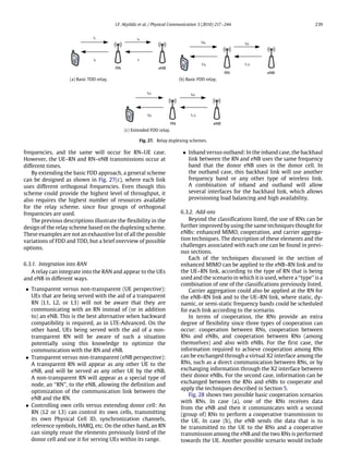
![240 I.F. Akyildiz et al. / Physical Communication 3 (2010) 217–244
(a)
(b)
Fig. 28. Cooperation schemes for relay networks.
a combination of (a) and (b); the eNB will establish a
cooperative transmission towards the UE with the RNs
while at the same time the RNs will communicate among
themselves to achieve cooperation.
Even though the cooperation scheme has been de-
scribed for a single cell and two hops, more complex sce-
narios in which more than two hops occur and more than
a single cell is taken into account can also be analyzed. In
the case of more than one cell, an RN could have more than
one donor eNB which adds a new degree of freedom for the
cooperation mechanisms.
However, as the number of RNs, their complexity, and
features required for a specific scenario increase, their cost
will also increase, which goes against the main idea of
using RNs: a low-cost alternative to improve performance
and coverage. Hence, a balance between the number of
RNs, their features, and their cost is one of the key points
for a wide successful deployment of RNs.
6.4. Topologies
The most basic topology for the deployment of RNs
consists of a single RN served by a single donor eNB and
serving a group of UEs. If the RN is located at the cell-edge
it could be used to extend the coverage of the network
or improve the cell-edge throughput, as shown in case
(c) of Fig. 26. If it is located within the cell coverage, the
RN could improve the coverage in areas where the eNB
is not providing adequate coverage or no coverage at all;
this corresponds to cases (b)–(f) of Fig. 26. The next basic
topology of RNs would consist of a single path of RNs where
each one can communicate with two other RAN elements
(another RN or an eNB), this topology corresponds to case
(a) of Fig. 26. If in the previous topologies we replace each
single RN with a group of RNs we can obtain cases (a)
and (b) of Fig. 28. As previously analyzed, each topology
can be mapped to different deployment scenarios. One of
the challenges consists in identifying which topologies and
which types of RN are more suitable in order to achieve the
objectives in the most common deployment scenarios.
6.5. Research challenges
The previous section showed the high level of flexibility
that the use of RNs introduces into the RAN. Even though
extensive research has been done in terms of analyzing the
achievable gains through the use of RNs in different mobile
multi-hop relay network scenarios, integrating relays into
a system such as LTE involves several constraints and
functionality that must be taken into account.
6.5.1. Architecture
The introduction of RNs into the RAN is already consid-
ered in LTE-Advanced, by indicating that at least ‘‘type 1’’
and ‘‘type 1a’’ relays should be supported, as described at
the beginning of this section.
Based on the description of the functionalities that
relays should provide in LTE-Advanced, some ideas on the
type of relays that should be used can be inferred. On the
Uu interface (Fig. 25) all AS control plane (RRC) and user
plane (PDCP, RLC, MAC) protocols are terminated in the RN,
which suggests the use of L2 or L3 relays. The use of RNs
should also be backward compatible with Release 8 UEs,
which suggests that RNs should support transparent (from
the UE point of view) mode, allowing a non-transparent
mode for LTE-Advanced UEs. However, the advantage of
using a non-transparent RN still has to be shown, i.e. having
UEs that are aware of transmission coming from an RN
instead of an eNB must prove to increase efficiency without
adding excessive complexity/cost to the UE and RAN.
This could be the case for cooperative transmission of
RNs and eNBs, where the UE awareness could reduce the
complexity of the scheme.
The characteristics of the eNB–RN link and the aware-
ness of eNB of RNs should also be taken into account. First,
on the Un interface between RNs and eNB, the user plane
is based on standardized protocols (PDCP, RLC, MAC) while
the control plane uses RRC (for the RN in its role as UE). Sec-
ond, at least at an early stage, most RNs will be fixed instead
of mobile. Third, the addition of a dedicated ‘‘relay control
channel’’ and ‘‘relay data channel’’ for the Un interface sug-
gests the use of non-transparent (from the eNB point of
view) RNs. These three characteristics (standard user and
control plane protocols, fixed RNs, eNB awareness of RNs)
can be used to optimize the protocols in the eNB–RN link,
in order to reduce their overhead and improve their per-
formance.
Beyond the characteristics (‘‘type 1’’ and ‘‘type 1a’’)
initially suggested by 3GPP for RNs, there exists the
possibility of creating other ‘‘types’’, based on a combi-
nation of the features described in Section 6.2. However,
their performance in different topologies, as shown in Sec-
tion 6.4, and scenarios, as shown in Section 6.1, needs to be
studied not only from a theoretical point of view but also
from a compatibility (with LTE-Advanced) and backward
compatibility with a Release 8 UE point of view.
The evaluation of the economic and theoretic aspects
of relay-enhanced networks, and real deployment perfor-
mance has already started for some relay ‘‘types’’ and sce-
narios. In [77], a techno-economic analysis of a generic
cellular-relay networks according to the fairness goals of
the operator is done. It is found that relays are best suited
for providing coverage for guaranteed data rates, rather
than to boost the data rate in specific locations. [78] pro-
vides an analysis of the effect of generic L2 relays on
coverage for LTE-Advanced. Their proposed evaluation
framework relates the transmission power of the RN, the](https://image.slidesharecdn.com/georgiatech2010-150530225436-lva1-app6891/85/Georgia-tech-2010-24-320.jpg)
![I.F. Akyildiz et al. / Physical Communication 3 (2010) 217–244 241
ratio between the number of eNBs and RNs, and the per-
formance of the system. [79] analyzes the performance
of L2 relays taking into account distributed SFBC for two-
antenna relays, while [80] analyzes timing asynchronism
in L1 cooperating relays with distributed STBC. [81] ana-
lyzes the throughput of cooperative and dynamic resource
relaying at a system level. The results obtained in these
papers have shown that the addition of cooperation and
enhanced MIMO techniques can significantly increase the
performance of a relay-enhanced network, but at the same
the use of such techniques should adapt to the specific de-
ployment scenarios. [82] provides measurements on the
performance of an L2 relay in an indoor full-frequency
reuse environment, showing that relays may be a viable
solution for indoor environments. [83] performs coverage
and capacity analysis of relay performance based on a 3D
models of a city, providing a more realistic view of the ap-
plication of relays and achievable improvements in a cel-
lular network.
6.5.2. Functionality
As described before, RRC, PDCP, RLC, and MAC are
terminated at the RN for the Uu interface. Identifying
up to what level each of these protocols will depend on
information provided by the eNBs or the core network
needs to be defined, as well as the methods in which
such information is obtained. Also, the amount of resources
available in the backhaul link will affect the way each
of these protocols behave. For example, in the case of
admission control two cases could occur.
• The RN is completely controlled by the eNB. Based on
the amount of resources that an RN is assigned (and
its capabilities), the RN is able to communicate with its
own UEs. If the amount of resources needed to serve the
UEs is more than the amount of resources the RN has
available, then some UEs may not be served.
• The RN ‘‘negotiates’’ with the eNB. Based on the amount
of resources that an RN needs to communicate with its
UEs, according to the required QoS, an RN will negotiate
with the eNB the amount of resources that it needs. In
this case, the eNB can assign all (or part) of the resources
that the RN requested, based on network policies or any
other criteria.
Handover procedures will also be affected. Simple
aspects in the handover procedure that need to be analyzed
in the presence of relays are depicted in Fig. 29.
In Fig. 29, the following types of handover could occur
(assuming the UE is being served initially by RN_1).
• From RN_1 to eNB_1: UE moves from the RN_1 cell to
be served directly by the eNodeB_1.
• From RN_1 to RN_2: UE moves from the RN_1 cell to be
served by RN_2, that is also served by the same donor
cell.
• From RN_1 to RN_3: UE moves from the RN_1 cell to be
served by RN_3, that is served by a different donor cell.
• From RN_1 to eNB_2: UE moves from the RN_1 cell to
be served by another eNodeB on another cell.
In addition to these basic handover procedures, more
complex ones also need to be studied, such as when MIMO
techniques, carrier aggregation, and CoMP are used.
Fig. 29. Handover with RNs.
6.5.3. Location and type of relay
The location of an RN will directly affect the perfor-
mance improvement that it can provide to the network.
The optimal location will be determined not only by the
scenario in which the RN will be deployed, but also by other
factors, such as the following.
• Coverage provided by other RNs and eNBs.
• RN ‘‘type’’ and ‘‘add-ons’’ (MIMO, carrier aggregation,
CoMP).
• Type of cooperation between RNs.
As has been described in previous section, the full set of
characteristics that an RN has is open to several variations.
However, which variations are more suitable to different
scenarios in order to provide high efficiency, in terms
of performance and cost, deployment options should be
studied.
6.5.4. Resource management
There are two RRM main areas related to the use of
RNs: RRM performed by the donor eNB and RRM done by
the RN. In the first case, the eNB is not only in charge of
doing RRM for its own UEs but also for the RNs that it is
serving. The eNB, being aware of the presence of RNs, must
make a balance between scheduling resources for its UE
and RNs not only to guarantee the QoS requirements but
also fairness, while taking into account interference and
any other constraints and policies. In the second case, the
RN is in charged of performing similar RRM as the one done
by a typical eNB, with the additional constraint that it has
a limited set of resources to communicate with the core
network due to the wireless RN–eNB backhaul link.
In the case of interference management at the level
of eNBs, LTE has already proposed some techniques
to achieve it by exchanging information between eNBs
through the X2 interface. Similar techniques could also
be applied for interference management between relay
nodes, taking into account the lack of a direct X2 interface
between RNs and eNBs.
Due to the possibility of achieving cooperation among
eNBs and RNs, as depicted in Fig. 28, RNs will also require
the exchange of channel state information regarding
RN–RN links and RN–eNB links. Also, depending on the
cooperation scenario, a certain level of integration and
support of the RN by the eNB would be required.](https://image.slidesharecdn.com/georgiatech2010-150530225436-lva1-app6891/85/Georgia-tech-2010-25-320.jpg)
![242 I.F. Akyildiz et al. / Physical Communication 3 (2010) 217–244
6.5.5. Routing
Due to their expected lower cost, more than one RN
could be deployed to satisfy a requirement (improved
coverage or throughput) in a specific area. This immedi-
ately raises the question on how to route the information
through this network of RNs, while satisfying QoS, fair-
ness, and interference requirements and constraints. At the
same time, the use of more than one RN in an area opens
the possibility of other features such as load balancing
and fault tolerance. The basic alternatives go around doing
centralized or distributed routing decisions, with their in-
herent optimality and scalability trade-off. As with other
topics related to RNs, they have been studied from a the-
oretical point of view, but need to be integrated into the
LTE-Advanced network with its requirements, constraints
and architecture.
6.5.6. User equipment as relay
The possibility of using UEs as RNs is not one of the
main approaches followed by LTE-Advanced to improve
coverage and performance. However, this capability can
be of high importance in emergency situations where the
availability of eNBs and fixed RNs infrastructure is reduced.
This scenario is characterized as being not frequent, and
no a priori information of the time in which it will be
required is known. In such cases, using other UEs as relays
could allow a flexible solution, but poses new challenges.
Battery consumption would be one of the main problems.
Also efficient procedures for searching UEs in emergency
situations, routing, and selection of the most appropriate
UE relay would be needed [76].
In general, the main research challenge of a relay-
enhanced network is to achieve the introduction of RNs
into the network while still meeting the performance
targets (average and peak throughput within and at the
cell-edge, and delay) and providing improvements in the
network.
7. Conclusions
LTE-Advanced, the backward-compatible enhancement
of LTE Release 8, will be fully specified in 3GPP Release
10. It has already been submitted as 3GPP’s 4G candidate
radio interface technology to ITU-R. We have described its
main technologies: carrier aggregation, enhanced MIMO,
cooperative multipoint transmission and reception, and
relays. For each one, we have examined their benefits,
challenges, and some existing approaches to tackle these
challenges. However, several issues in each of them are still
open and require further research.
It is the combination of these technologies, and not
just a single one, that will enable achieving the target
performance requirements established by IMT-Advanced.
The development and integration of this elements will not
end with 3GPP Release 10, but will provide the starting
point for their implementation.
In addition to the elements that we have examined in
this paper, it is also expected that the use of femtocells,
self-organizing networks, and energy management sys-
tems will drive the evolution of current and future mobile
wireless networks.
Acknowledgements
The authors would like to thank Ozgur B. Akan, Mehmet
C. Vuran, Won-Yeol Lee and Linda Xie for their valuable
comments that improved the quality of this paper. This
material is based upon work supported by the Obra Social
‘‘la Caixa’’ and the ‘‘SENACYT’’ fellowship.
References
[1] ITU-R, Circular letter 5/LCCE/2, Tech. Rep., March 2008.
[2] ITU-R, Acknowledgment of candidate submission from 3GPP
proponent under step 3 of the IMT-Advanced process (3GPP
technology), Tech. Rep., October.
[3] ITU-R, Acknowledgment of candidate submission from IEEE under
step 3 of the IMT-Advanced process (IEEE technology), Tech. Rep.,
October.
[4] ITU-R, Acknowledgment of candidate submission from China
(People’s Republic of) under step 3 of the IMT-Advanced process
(3GPP technology), Tech. Rep., October.
[5] ITU-R, Requirements related to technical performance for IMT-
Advanced radio interface(s), Report M.2134, 2008.
[6] 3GPP, TR 36.913 Requirements for further advancements for Evolved
Universal Terrestrial Radio Access (E-UTRA) (LTE-Advanced), Tech.
Rep., December 2009 [Online]. Available: http://ftp.3gpp.org/specs/
html-info/36913.htm.
[7] 3GPP, Overview of 3GPP release 8 v.0.1.1, Tech. Rep., June 2010.
[8] 3GPP, TS 36.323 Packet Data Convergence Protocol (PDCP) specifi-
cation, Tech. Rep., December 2009 [Online]. Available: http://www.
3gpp.org/ftp/Specs/html-info/36323.htm.
[9] 3GPP, TS 36.322 Radio Link Control (RLC) protocol specification,
Tech. Rep., March 2010 [Online]. Available: http://www.3gpp.org/
ftp/Specs/html-info/36322.htm.
[10] 3GPP, TS 36.321 Medium Access Control (MAC) protocol specifica-
tion, Tech. Rep., March 2010 [Online]. Available: http://www.3gpp.
org/ftp/Specs/html-info/36321.htm.
[11] 3GPP, TS 36.331 Radio Resource Control (RRC), Tech. Rep., March
2010 [Online]. Available: http://www.3gpp.org/ftp/Specs/html-
info/36331.htm.
[12] T. Tjelta, A.L. Lillebo, E.O. Evenstad, ITU-R world radiocom-
munication conference 2007, Telektronikk 1 (2008) 144–159.
[Online]. Available: http://www.telenor.com/telektronikk/volumes/
pdf/1.2008/Page_144-159.pdf.
[13] 3GPP, TR 36.912 Feasibility study for further advancements for E-
UTRA (LTE-Advanced), Tech. Rep., June 2010 [Online]. Available:
http://www.3gpp.org/ftp/Specs/html-info/36912.htm.
[14] Nokia, R4-091204 study of UE architectures for LTE-A deployment
scenarios, Tech. Rep., March 2009 [Online]. Available: http://ftp.
3gpp.org/tsg_ran/WG4_Radio/TSGR4_50bis/Documents/R4091204.
zip.
[15] M. Tanno, Y. Kishiyama, H. Taoka, N. Miki, K. Higuchi, M. Sawahashi,
Layered OFDMA radio access for IMT-Advanced, in: Proc. VTC 2008-
Fall Vehicular Technology Conf. IEEE 68th, 2008, pp. 1–6.
[16] CELTIC/CP5-026 WINNER+, D3.2 aspects of WINNER+ spectrum
preferences, Tech. Rep., May 2009.
[17] R. Agusti, O. Salient, J. Perez-Romero, L. Giupponi, A fuzzy-
neural based approach for joint radio resource management in a
beyond 3G framework, in: Proc. First Int. Conf. Quality of Service
in Heterogeneous Wired/Wireless Networks QSHINE 2004, 2004,
pp. 216–224.
[18] E. Mino, J. Luo, E. Tragos, A. Mihovska, Scalable and hybrid radio
resource management for future wireless networks, in: Proc. 16th
IST Mobile and Wireless Communications Summit, 2007, pp. 1–5.
[19] O. Sallent, R. Agusti, J. Perez-Romero, L. Giupponi, Decentralized
spectrum and radio resource management enabled by an on-
demand cognitive pilot channel, Ann. Telecommun. 63 (5–6)
(2008) 281–294 [Online]. Available: http://www.springerlink.com/
content/y16545l2v36umx60/.
[20] 3GPP, TR 22.951 Service aspects and requirements for network
sharing, Tech. Rep., December 2009 [Online]. Available: http://ftp.
3gpp.org/specs/html-info/22951.htm.
[21] 3GPP, TS 23.251 Network sharing; architecture and functional
description, Tech. Rep., March 2010 [Online]. Available: http://ftp.
3gpp.org/Specs/html-info/23251.htm.
[22] CELTIC/CP5-026 WINNER+, D1.2 initial report on system aspects of
flexible spectrum use, Tech. Rep., January 2009.](https://image.slidesharecdn.com/georgiatech2010-150530225436-lva1-app6891/85/Georgia-tech-2010-26-320.jpg)
![I.F. Akyildiz et al. / Physical Communication 3 (2010) 217–244 243
[23] A. Mihovska, F. Meucci, N.R. Prasad, F.J. Velez, O. Cabral, Multi-
operator resource sharing scenario in the context of IMT-Advanced
systems, in: Proc. Second Int. Workshop Cognitive Radio and
Advanced Spectrum Management CogART 2009, 2009, pp. 12–16.
[24] I.F. Akyildiz, W.-Y. Lee, M.C. Vuran, S. Mohanty, Next genera-
tion/dynamic spectrum access/cognitive radio wireless networks:
a survey, Comput. Netw. 50 (13) (2006) 2127–2159 [Online].
Available: http://www.sciencedirect.com/science/article/B6VRG-
4K00C5M-4/2/3ad0ce34d1af95ffc509bf0ccaa455ab.
[25] D.M. Akos, M. Stockmaster, J.B.Y. Tsui, J. Caschera, Direct bandpass
sampling of multiple distinct RF signals, IEEE Trans. Commun. 47 (7)
(1999) 983–988.
[26] R.G. Vaughan, N.L. Scott, D.R. White, The theory of bandpass
sampling, IEEE Trans. Signal Process. 39 (9) (1991) 1973–1984.
[27] T. Kitayabu, Y. Ikeda, Y. Amano, H. Ishikawa, Concurrent dual-band
receiver for spectrum aggregation system, in: Proc. IEEE Radio and
Wireless Symp. RWS’09, 2009, pp. 634–637.
[28] 3GPP, TS 36.104 Base Station (BS) radio transmission and reception,
Tech. Rep., September 2009 [Online]. Available: http://www.3gpp.
org/ftp/Specs/html-info/36104.htm.
[29] J. Dixon, C. Politis, C. Wijting, W. Mohr, C. Legutko, J. Jian, Consid-
erations in the choice of suitable spectrum for mobile communica-
tions, in: Wireless World Research Forum, White Paper 2, November
2008 [Online]. Available: http://www.wireless-world-research.org/
fileadmin/sites/default/files/publications/Outlook/Outlook2.pdf.
[30] S. Songsong, F. Chunyan, G. Caili, A resource scheduling algorithm
based on user grouping for LTE-Advanced system with carrier
aggregation, in: Proc. Int. Symp. Computer Network and Multimedia
Technology CNMT 2009, 2009, pp. 1–4.
[31] K. Doppler, C. Wijting, J.-P. Kermoal, Multi-band scheduler for fu-
ture communication systems, in: Proc. Int. Conf. Wireless Commu-
nications, Networking and Mobile Computing WiCom 2007, 2007,
pp. 6744–6748.
[32] F. Meucci, O. Cabral, F.J. Velez, A. Mihovska, N.R. Prasad, Spectrum
aggregation with multi-band user allocation over two frequency
bands, in: Proc. IEEE Mobile WiMAX Symp. MWS’09, 2009,
pp. 81–86.
[33] L. Chen, W. Chen, X. Zhang, D. Yang, Analysis and simulation for
spectrum aggregation in LTE-Advanced system, in: Proc. IEEE 70th
Vehicular Technology Conf. Fall, VTC 2009-Fall, 2009, pp. 1–6.
[34] Alcatel-Lucent Shanghai Bell, Alcatel-Lucent, R1-093347 Al-
gorithm and performance evaluations for DL non-coherent
multi-user joint transmission scheme, Tech. Rep., August 2009
[Online]. Available: http://www.3gpp.org/ftp/tsg_ran/wg1_rl1/
TSGR1_58/Docs/R1093347.zip.
[35] K. Takeda, S. Nagata, Y. Kishiyama, M. Tanno, K. Higuchi, M.
Sawahashi, Investigation on optimum radio parameter design in
layered OFDMA for LTE-Advanced, in: Proc. IEEE 69th Vehicular
Technology Conf. VTC Spring 2009, 2009, pp. 1–5.
[36] F. Shu, L. Lihua, T. Xiaofeng, Z. Ping, A spatial multiplexing MIMO
scheme with beamforming for downlink transmission, in: Proc. VTC-
2007 Fall Vehicular Technology Conf. 2007 IEEE 66th, 2007, pp.
700–704.
[37] I.H. Kim, K. Lee, J. Chun, A MIMO antenna structure that combines
transmit beamforming and spatial multiplexing, IEEE Trans. Wire-
less Commun. 6 (3) (2007) 775–779.
[38] H. Bolcskei, R.U. Nabar, V. Erceg, D. Gesbert, A.J. Paulraj, Performance
of spatial multiplexing in the presence of polarization diversity,
in: Proc. IEEE Int. Conf. Acoustics, Speech, and Signal Processing,
ICASSP’01, vol. 4, 2001, pp. 2437–2440.
[39] S. Saur, H. Halbauer, A. Rueegg, Schaich, Grid-of-Beams (GoB)
based downlink multi-user MIMO, Alcatel-Lucent, Contribution to
IEEE 802.16m C802.16m-08/487, May 2008 [Online]. Available:
http://www.ieee802.org/16/tgm/contrib/C80216m08_487.doc.
[40] G. Caire, S. Shamai, On achievable rates in a multi-antenna Gaussian
broadcast channel, in: Proc. IEEE Int. Information Theory Symp.,
2001.
[41] H. Viswanathan, S. Venkatesan, H. Huang, Downlink capacity eval-
uation of cellular networks with known-interference cancellation,
IEEE J. Sel. Areas Commun. 21 (5) (2003) 802–811.
[42] M. Costa, Writing on dirty paper (corresp.), IEEE Trans. Inform.
Theory 29 (3) (1983) 439–441.
[43] A. Tarighat, M. Sadek, A.H. Sayed, A multi user beamforming
scheme for downlink MIMO channels based on maximizing signal-
to-leakage ratios, in: Proc. IEEE Int. Conf. Acoustics, Speech, and
Signal Processing, ICASSP’05, vol. 3, 2005.
[44] Q.H. Spencer, A.L. Swindlehurst, M. Haardt, Zero-forcing methods
for downlink spatial multiplexing in multiuser MIMO channels, IEEE
Trans. Signal Process. 52 (2) (2004) 461–471.
[45] Nokia Siemens Networks, Nokia, R1-090726 single-stream precod-
ing for LTE-Advanced UL, Tech. Rep., February 2009.
[46] Ericsson, R1-091573 Uplink SU–MIMO in LTE-Advanced, Tech. Rep.,
February 2009.
[47] 3GPP, Final report of 3GPP TSG RAN WG1 #56bis v.2.0.0, Tech. Rep.,
2009.
[48] Qualcomm Europe, R1-091462 PUCCH transmit diversity, Tech. Rep.,
March 2009.
[49] Nortel, R1-091374 Evaluation of transmit diversity for PUCCH in
LTE-A, Tech. Rep., March 2009.
[50] Huawei, R1-091277 TX diversity scheme criteria for PUSCH, Tech.
Rep., March 2009.
[51] Qualcomm Europe, R1-091463 PUSCH transmit diversity, Tech. Rep.,
March 2009.
[52] Nokia Siemens Networks, Nokia, R1-092579 TX diversity for LTE-
Advanced PUSCH, Tech. Rep., June 2009.
[53] A. Varikat, V.R. Thumparthy, B. Somayaji, A. Gunaseelan, K.
Giridhar, Virtual MIMO communication, Contribution to IEEE
802.16m C802.16m-07/305r1, November 2007 [Online]. Available:
http://www.ieee802.org/16/tgm/contrib/C80216m07_305r1.doc.
[54] Y. Yang, R.S. Blum, S. Sfar, Antenna selection for MIMO systems with
closely spaced antennas, EURASIP J. Wirel. Commun. Netw. 2009
(2009) 1–11.
[55] A. Haghighat, Z. Lin, G. Zhang, Haar compression for efficient cqi
feedback signaling in 3GPP LTE systems, in: Proc. IEEE Wireless
Communications and Networking Conf. WCNC 2008, 2008, pp.
819–823.
[56] R. Vannithamby, H. Sun, Z. Ma, L. Li, G. Li, H. Yang, R. Srinivasan, H.
Yin, CQI feedback framework—details, Intel Corporation, Contribu-
tion to IEEE 802.16m C802.16m-08/710r1, July 2008 [Online]. Avail-
able: http://www.ieee802.org/16/tgm/contrib/C80216m08_710r1.
pdf.
[57] E. Bjornson, D. Hammarwall, B. Ottersten, Exploiting quantized
channel norm feedback through conditional statistics in arbitrarily
correlated MIMO systems, IEEE Trans. Signal Process. 57 (10) (2009)
4027–4041.
[58] Alcatel-Lucent, R1-083759 UE PMI feedback signalling for user
pairing/coordination, Tech. Rep., September 2008 [Online]. Avail-
able: http://www.3gpp.org/ftp/tsg_ran/wg1_rl1/TSGR1_54b/Docs/
R1083759.zip.
[59] Samsung, R1-082886 Inter-cell interference mitigation through
limited coordination, Tech. Rep., August 2008 [Online]. Avail-
able: http://www.3gpp.org/ftp/tsg_ran/wg1_rl1/TSGR1_54/Docs/
R1082886.zip.
[60] CELTIC/CP5-026 WINNER+, D1.4 initial report on advanced multiple
antenna systems, Tech. Rep., January 2009.
[61] A. Papadogiannis, H.J. Bang, D. Gesbert, E. Hardouin, Downlink
overhead reduction for multi-cell cooperative processing enabled
wireless networks, in: Proc. IEEE 19th Int. Symp. Personal, Indoor
and Mobile Radio Communications PIMRC 2008, 2008, pp. 1–5.
[62] Y. Song, L. Cai, K. Wu, H. Yang, Collaborative MIMO, Alcatel-Lucent,
Contribution to IEEE 802.16m C802.16m-07/244r1, November
2007 [Online]. Available: http://www.ieee802.org/16/tgm/contrib/
C80216m07_244r1.doc.
[63] Samsung, R1-083569 Further discussion on inter-cell interfer-
ence mitigation through limited coordination, Tech. Rep., Septem-
ber 2008 [Online]. Available: http://ftp.3gpp.org/tsg_ran/WG1_RL1/
TSGR1_54b/Docs/R1083569.zip.
[64] Motorola, R1-090793 coordinated multi-point transmission—
coordinated beamforming/precoding results, Tech. Rep., February
2009.
[65] Qualcomm, R1-083192 Network MIMO for downlink transmission
in LTE-Advanced, Tech. Rep., August 2008 [Online]. Available: http://
www.3gpp.org/ftp/tsg_ran/wg1_rl1/TSGR1_54/Docs/R1083192.zip.
[66] Nortel, R1-084464 Cell clustering for CoMP transmission/reception,
Tech. Rep., November 2008 [Online]. Available: http://www.3gpp.
org/ftp/tsg_ran/wg1_rl1/TSGR1_55/Docs/R1084464.zip.
[67] CATT, R1-090942 Aspects of joint processing for downlink CoMP,
Tech. Rep., February 2009 [Online]. Available: http://ftp.3gpp.org/
tsg_ran/WG1_RL1/TSGR1_56/Docs/R1090942.zip.
[68] Huawei, CMCC, RITT, CATT, R1-084336 Analysis on uplink/downlink
time delay issue for distributed antenna system, Tech. Rep.,
November 2008 [Online]. Available: http://www.3gpp.org/ftp/tsg_
ran/wg1_rl1/TSGR1_55/Docs/R1084336.zip.
[69] Huawei, R1-091618 System performance evaluation for uplink
CoMP, Tech. Rep., March 2009 [Online]. Available: http://ftp.3gpp.
org/tsg_ran/WG1_RL1/TSGR1_56b/Docs/R1091618.zip.
[70] 3GPP, Draft report of 3PP TSG RAN WG1 #59bis, Tech. Rep., 2010.
[71] P. Marsch, G. Fettweis, A framework for optimizing the uplink
performance of distributed antenna systems under a constrained
backhaul, in: Proc. IEEE Int. Conf. Communications ICC’07, 2007,
pp. 975–979.](https://image.slidesharecdn.com/georgiatech2010-150530225436-lva1-app6891/85/Georgia-tech-2010-27-320.jpg)
![244 I.F. Akyildiz et al. / Physical Communication 3 (2010) 217–244
[72] P. Marsch, G. Fettweis, A decentralized optimization approach to
backhaul-constrained distributed antenna systems, in: Proc. 16th
IST Mobile and Wireless Communications Summit, 2007, pp. 1–5.
[73] L. Thiele, M. Schellmann, S. Schiffermuller, V. Jungnickel, W. Zirwas,
Multi-cell channel estimation using virtual pilots, in: Proc. IEEE
Vehicular Technology Conf. VTC Spring 2008, 2008, pp. 1211–1215.
[74] 3GPP, TR 36.806 Relay architectures for E-UTRA (LTE-Advanced),
Tech. Rep., April 2010 [Online]. Available: http://www.3gpp.org/ftp/
specs/html-info/36806.htm.
[75] E. Seidel, Initial thoughts on LTE-Advanced for 3GPP release 10,
Nomor Research, May 2009 [Online]. Available: http://www.3g4g.
co.uk/LteA/LteA_Pres_0905_Nomor.pdf.
[76] Samsung, Future 3GPP radio technologies for IMT-Advanced,
April 2008 [Online]. Available: http://www.3gpp.org/ftp/workshop/
200804-07_RAN_IMT_Advanced/Docs/REV080037.zip.
[77] B. Timus, P. Soldati, J. Zander, Implications of fairness criteria on the
techno-economic viability of relaying networks, in: Proc. IEEE 69th
Vehicular Technology Conf. VTC Spring 2009, 2009, pp. 1–5.
[78] T. Beniero, S. Redana, J. Hamalainen, B. Raaf, Effect of relaying
on coverage in 3GPP LTE-Advanced, in: Proc. IEEE 69th Vehicular
Technology Conf. VTC Spring 2009, 2009, pp. 1–5.
[79] S. Teodoro, A. Silva, J.M. Gil, A. Gameiro, Distributed space-frequency
block coding for a 2-antenna relay in downlink OFDM systems, in:
Proc. 9th Int. Symp. Communications and Information Technology
ISCIT 2009, 2009, pp. 853–858.
[80] A. Yadav, M. Juntti, J. Karjalainen, Combating timing asynchronism
in relay transmission for 3GPP LTE uplink, in: Proc. IEEE Wire-
less Communications and Networking Conf. WCNC 2009, 2009,
pp. 1–6.
[81] E. Reetz, R. Hockmann, R. Tonjes, Performance evaluation of
topologies for cooperative and dynamic resource relaying, in: Proc.
14th European Wireless Conf. EW 2008, 2008, pp. 1–6.
[82] V. Venkatkumar, T. Wirth, T. Haustein, E. Schulz, Relaying in long
term evolution: indoor full frequency reuse, in: Proc. European
Wireless Conf. EW 2009, 2009, pp. 298–302.
[83] R. Schoenen, W. Zirwas, B.H. Walke, Capacity and coverage analysis
of a 3GPP-LTE multihop deployment scenario, in: Proc. IEEE Int. Conf.
Communications Workshops ICC Workshops’08, 2008, pp. 31–36.
Ian F. Akyildiz received the B.S., M.S., and
Ph.D. degrees in Computer Engineering from the
University of Erlangen-Nuernberg, Germany, in
1978, 1981 and 1984, respectively. Currently, he
is the Ken Byers Chair Professor with the School
of Electrical and Computer Engineering, Georgia
Institute of Technology, Atlanta, the Director
of Broadband Wireless Networking Laboratory
and Chair of the Telecommunication Group
at Georgia Tech. In June 2008, Dr. Akyildiz
became an honorary professor with the School
of Electrical Engineering at Universitat Politècnica de Catalunya (UPC)
in Barcelona, Spain. He is also the Director of the newly founded
N3Cat (NaNoNetworking Center in Catalunya). He is also an Honorary
Professor with University of Pretoria, South Africa, since March 2009.
He is the Editor-in-Chief of Computer Networks (Elsevier) Journal,
and the founding Editor-in-Chief of the Ad Hoc Networks (Elsevier)
Journal, the Physical Communication (Elsevier) Journal and the Nano
Communication Networks (Elsevier) Journal. Dr. Akyildiz serves on the
advisory boards of several research centers, journals, conferences and
publication companies. He is an IEEE FELLOW (1996) and an ACM FELLOW
(1997). He received numerous awards from IEEE and ACM. His research
interests are in nano-networks, cognitive radio networks and wireless
sensor networks.
David M. Gutierrez-Estevez obtained his Engi-
neering Degree in Telecommunications from the
School of Electrical Engineering, Universidad de
Granada, Granada, Spain, in July 2009. During
the summer of 2007 he held an internship po-
sition at the Audio Department of Fraunhofer
Institute for Integrated Circuits in Erlangen, Ger-
many. In 2007, he received an Erasmus schol-
arship to finish his Telecommunications Degree
at the Technische Universitaet Berlin, Germany.
From April 2008 to June 2009 he was a research
assistant within the Broadband Mobile Communications Networks De-
partment of the Fraunhofer Heinrich Hertz Institute in Berlin, where he
worked on projects linked to Long Term Evolution (LTE) cellular systems.
Currently, he is pursuing his M.S. and Ph.D. degrees at the Broadband
Wireless Networking Laboratory, School of Electrical and Computer Engi-
neering, Georgia Institute of Technology, Atlanta, with a fellowship from
Obra Social ‘‘la Caixa’’. His current research is focused on Next Generation
Cellular Networks. He is a student member of IEEE.
Elias Chavarria Reyes received the B.E. de-
gree in Electronics and Communication Engi-
neering from Universidad de Panamá, Ciudad de
Panamá, Panamá, in 2007. He received his M.S.
degree in Electrical and Computer Engineering
from the School of Electrical and Computer En-
gineering, Georgia Institute of Technology, At-
lanta, in 2010. Currently, he is pursuing his Ph.D.
degree in the Broadband Wireless Networking
Laboratory, School of Electrical and Computer
Engineering, Georgia Institute of Technology, At-
lanta, with a fellowship from ‘‘SENACYT’’. His current research is focused
on Next Generation Cellular Networks. He is a student member of IEEE.](https://image.slidesharecdn.com/georgiatech2010-150530225436-lva1-app6891/85/Georgia-tech-2010-28-320.jpg)