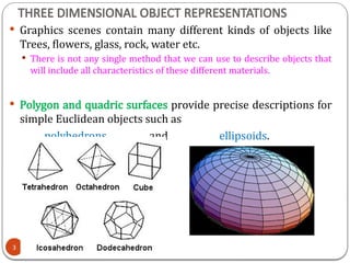
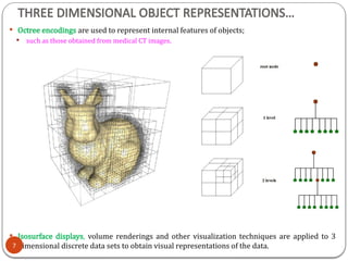
3D object representation refers to the methods used to mathematically define and store the shape and appearance of three-dimensional objects within a computer system. These representations are crucial for rendering realistic images, simulating physical interactions, and enabling various applications like gaming, virtual reality, and medical imaging.

![3. PLANE EQUATIONS
When working with polygons or polygon meshes, we need to know the
equation of the plane in which the polygon lies.
We can use the coordinates of 3 vertices to find the plane.
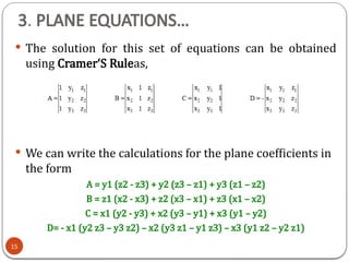
The plane equation is
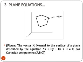
Ax + By + Cz + D = 0
The coefficients A, B and C define the normal to the plane [A B C].
We can obtain the coefficients A, B, C and D by solving a set of 3 plane
equations using the coordinate values for 3 non collinear points in the plane.
Suppose we have 3 vertices on the polygon (x1, y1, z1), (x2, y2, z2) and
(x3, y3, z3).
Ax + By + Cz + D = 0
(A/D) x1 + (B/D) y1 + (C/D) z1 = -1
(A/D) x2 + (B/D) y2 + (C/D) z2 = -1
(A/D) x3 + (B/D) y3 + (C/D) z3 = -1
14](https://image.slidesharecdn.com/05013d-objectrepresentation-250801111100-7a799243/85/3D-Object-Representation-in-Computer-Graphics-pptx-14-320.jpg)