Download as PPSX, PPTX

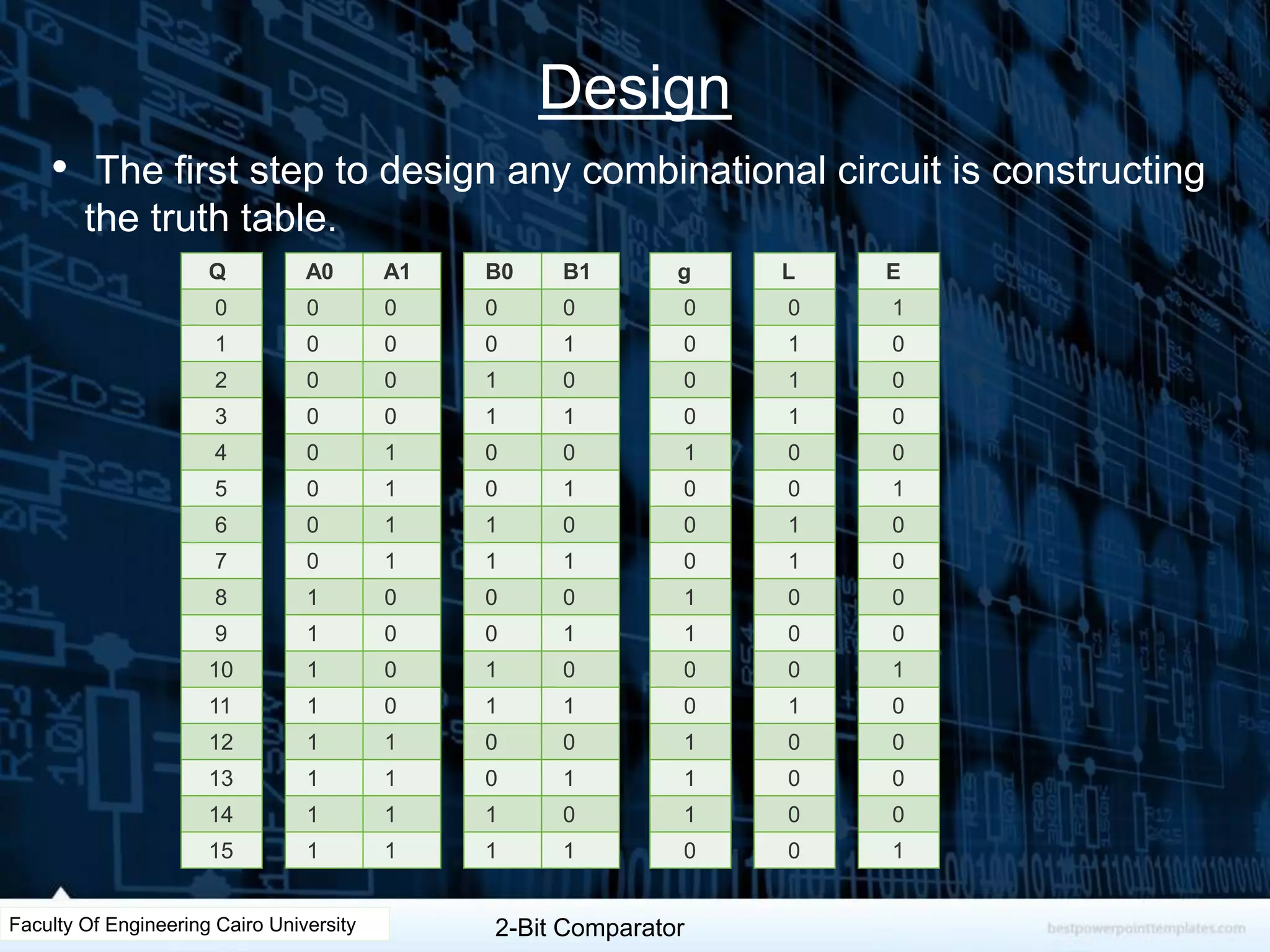
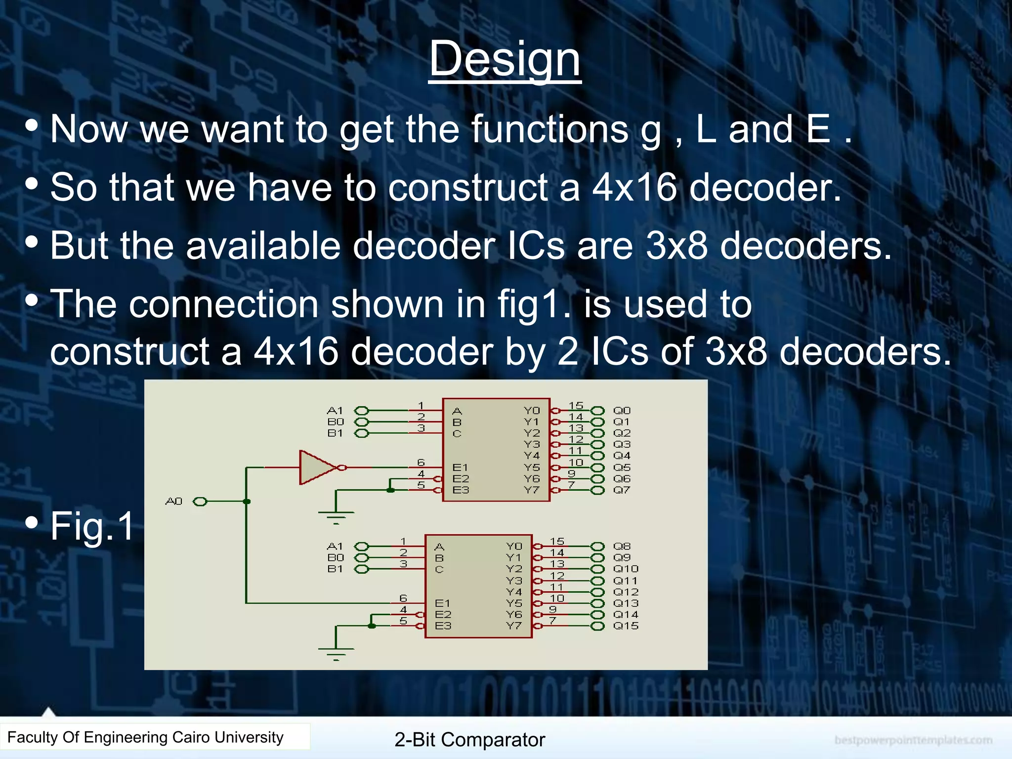
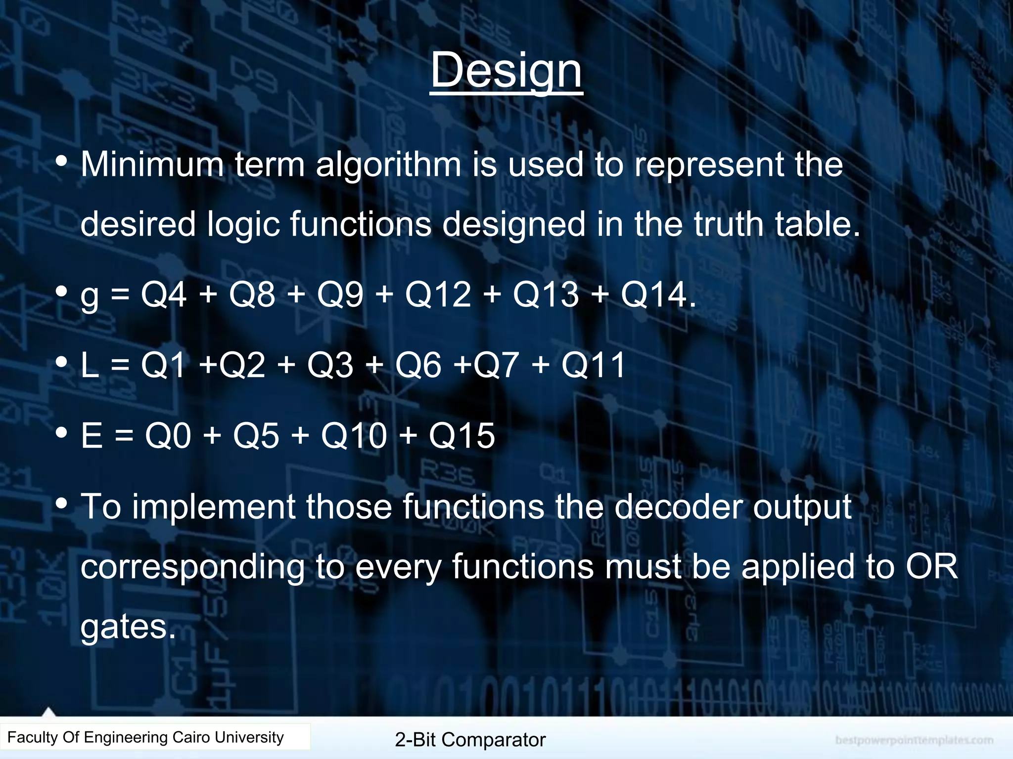
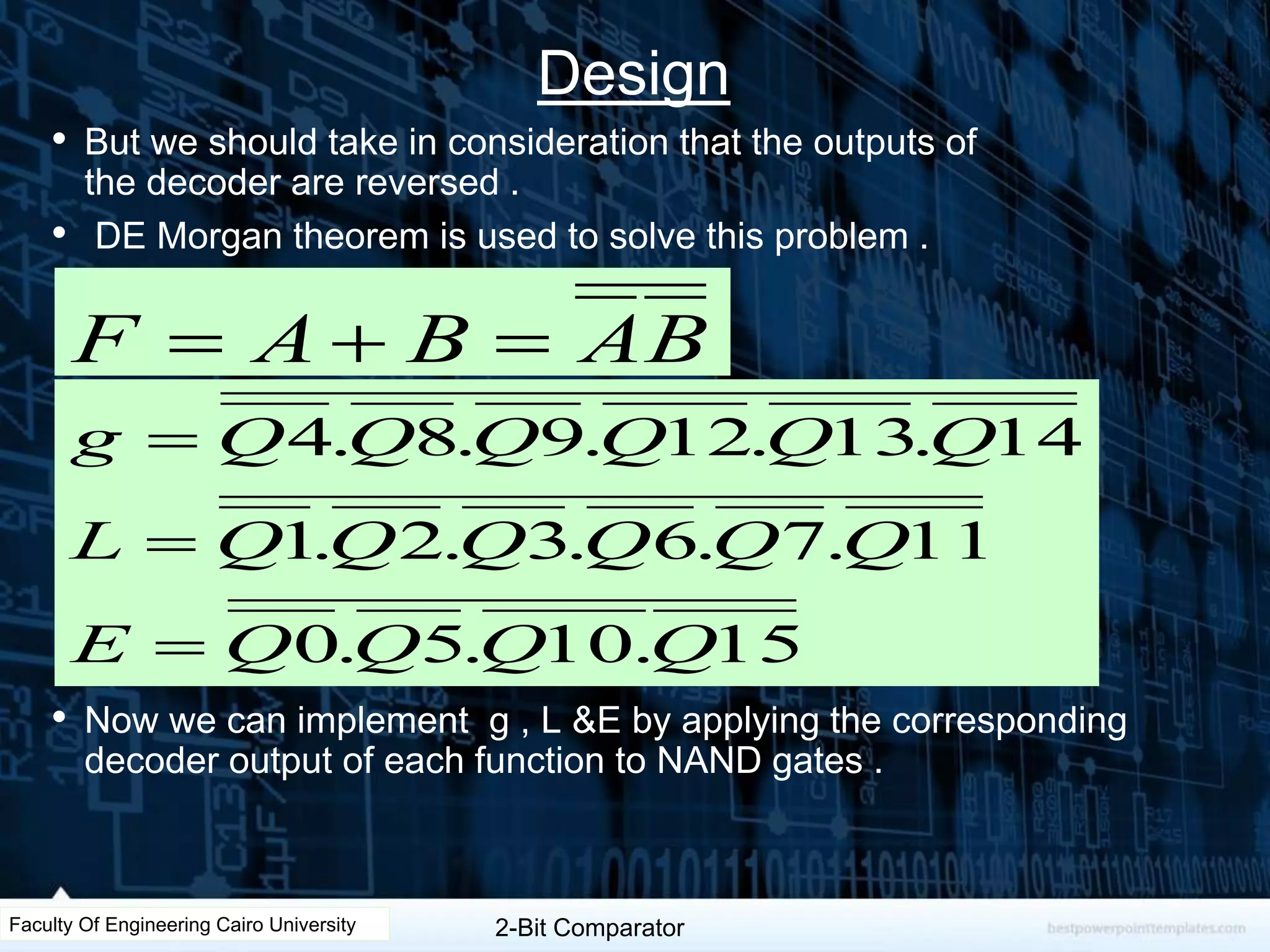
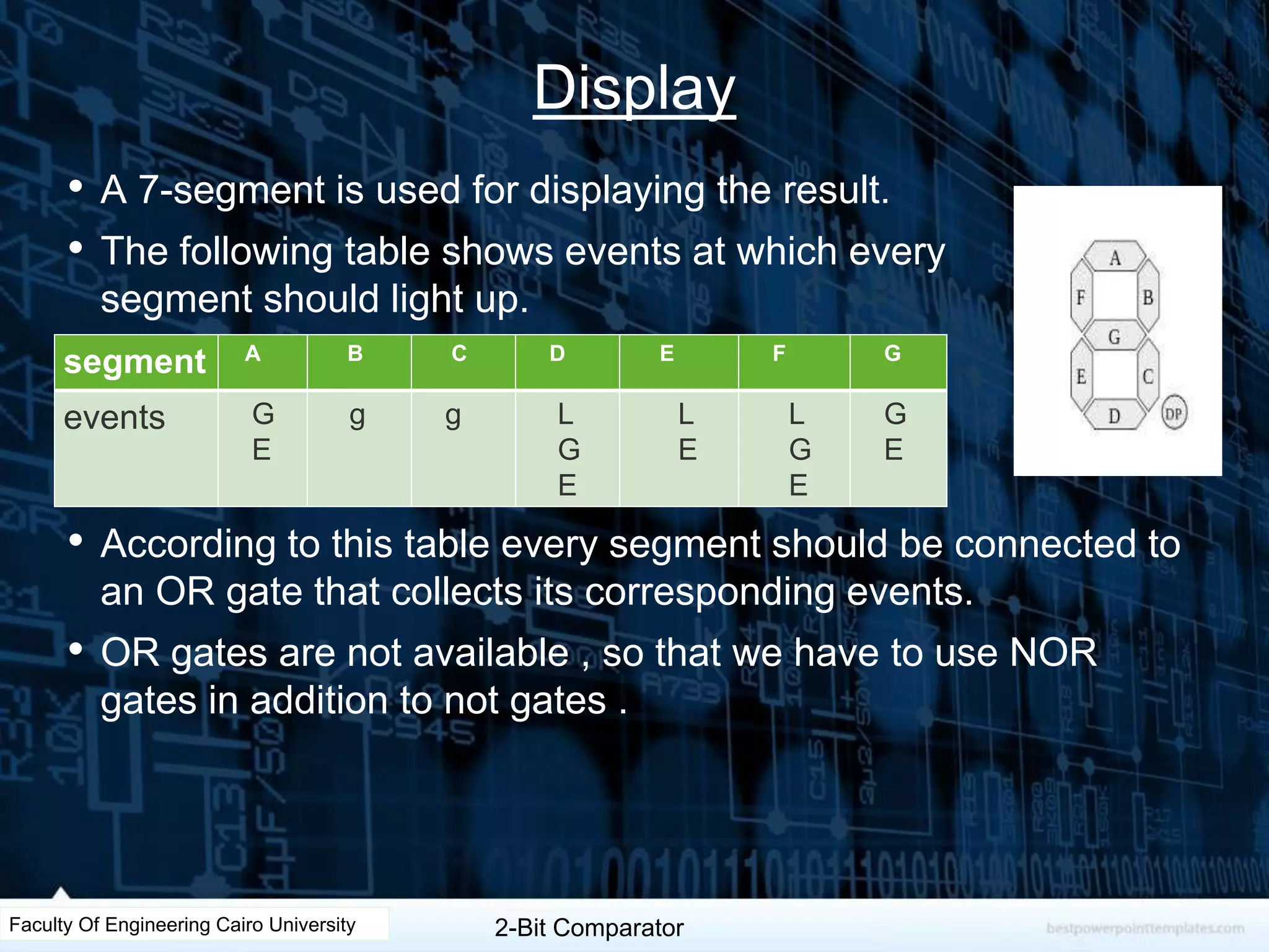

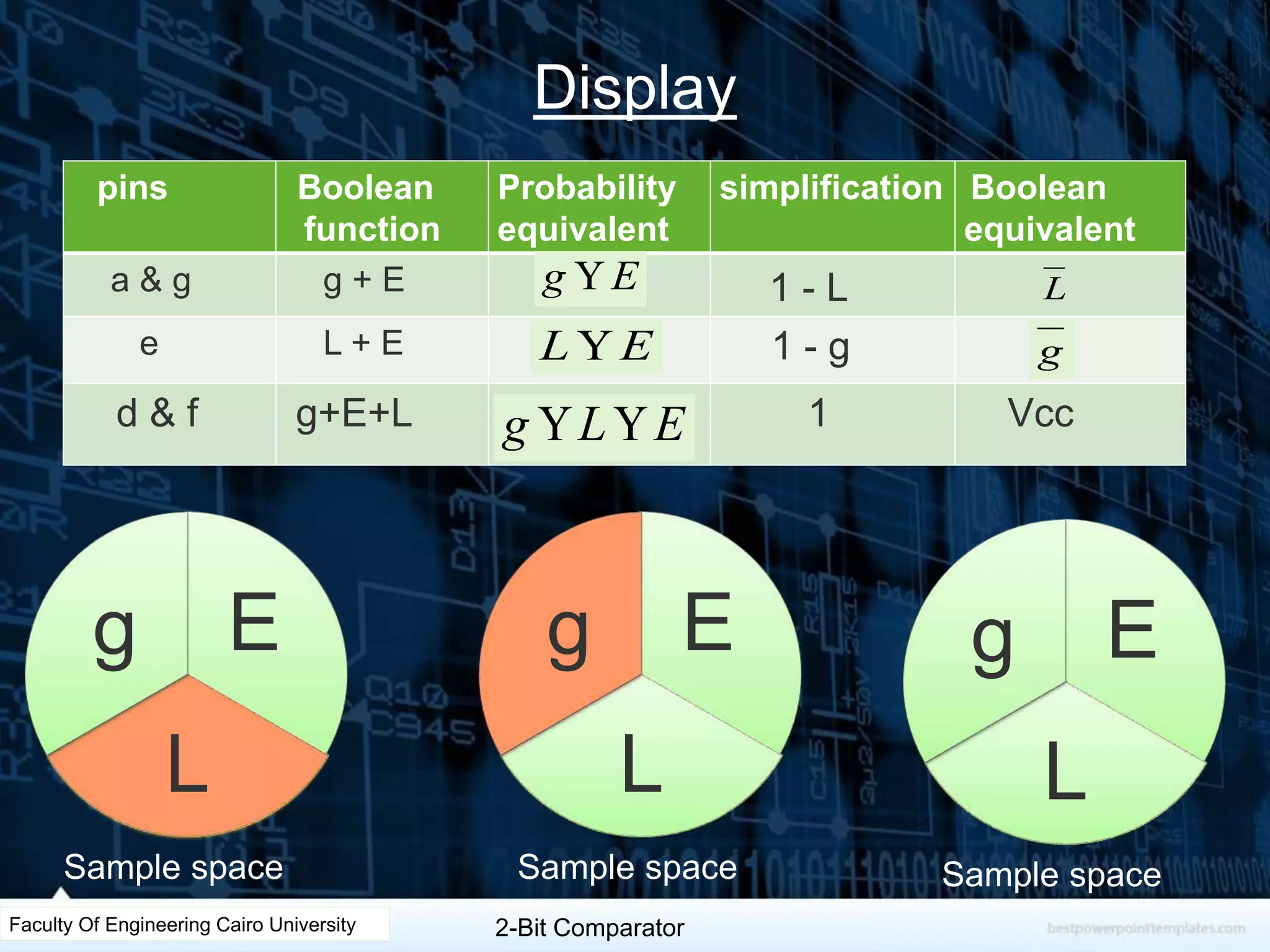
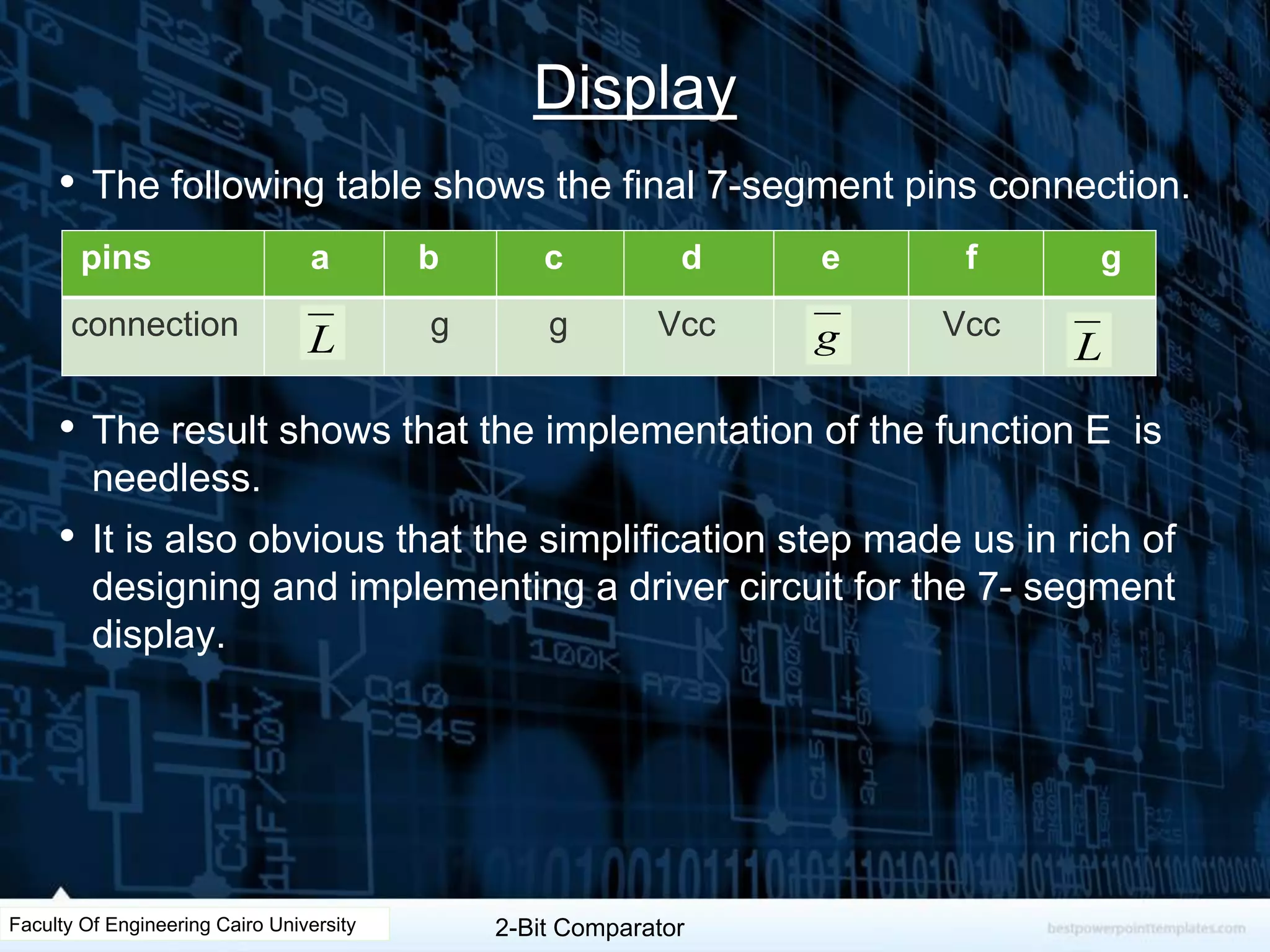
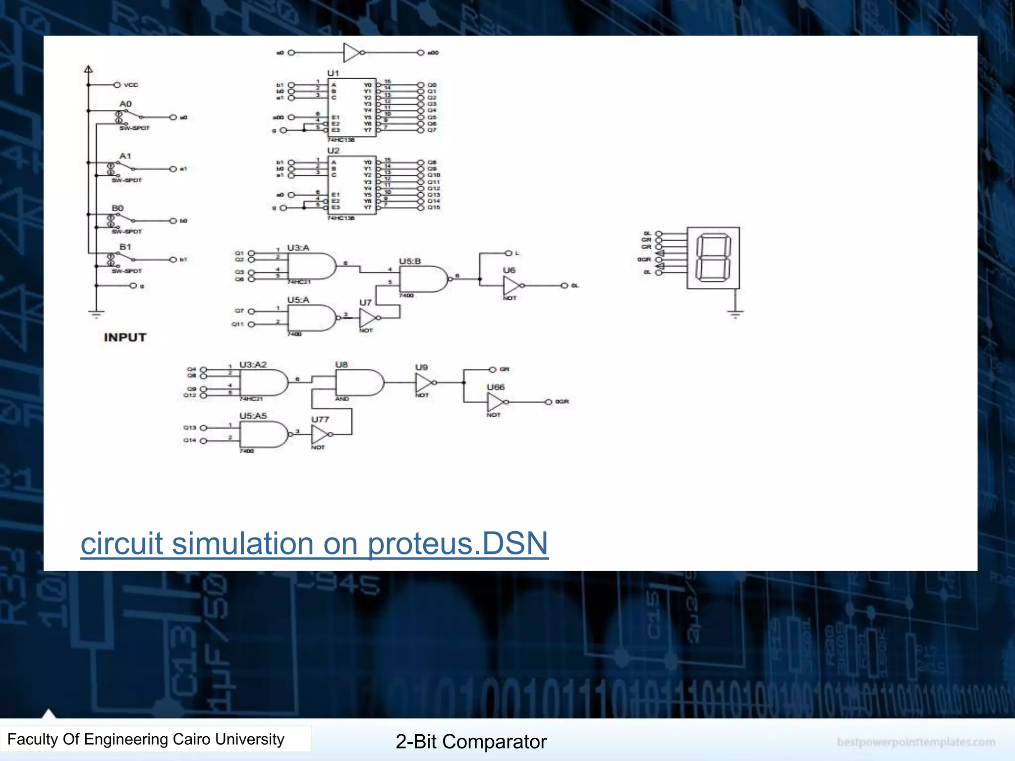

The document describes the design of a 2-bit comparator circuit. It includes constructing a truth table, minimizing the design using two 3x8 decoders as a 4x16 decoder, implementing the output functions G, L, and E using NAND gates, and displaying the output on a 7-segment display by simplifying the logic. The design was tested successfully through Proteus simulation software.