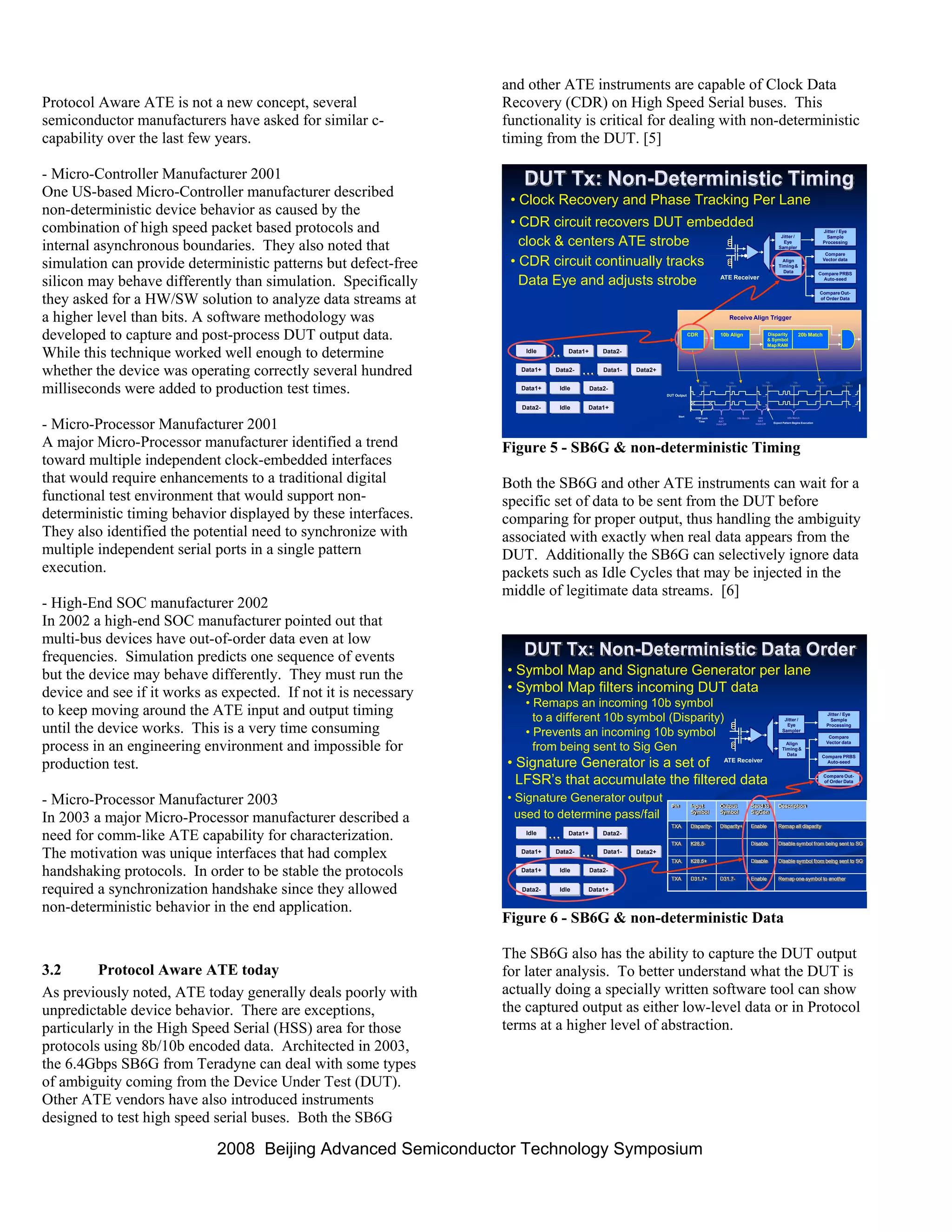
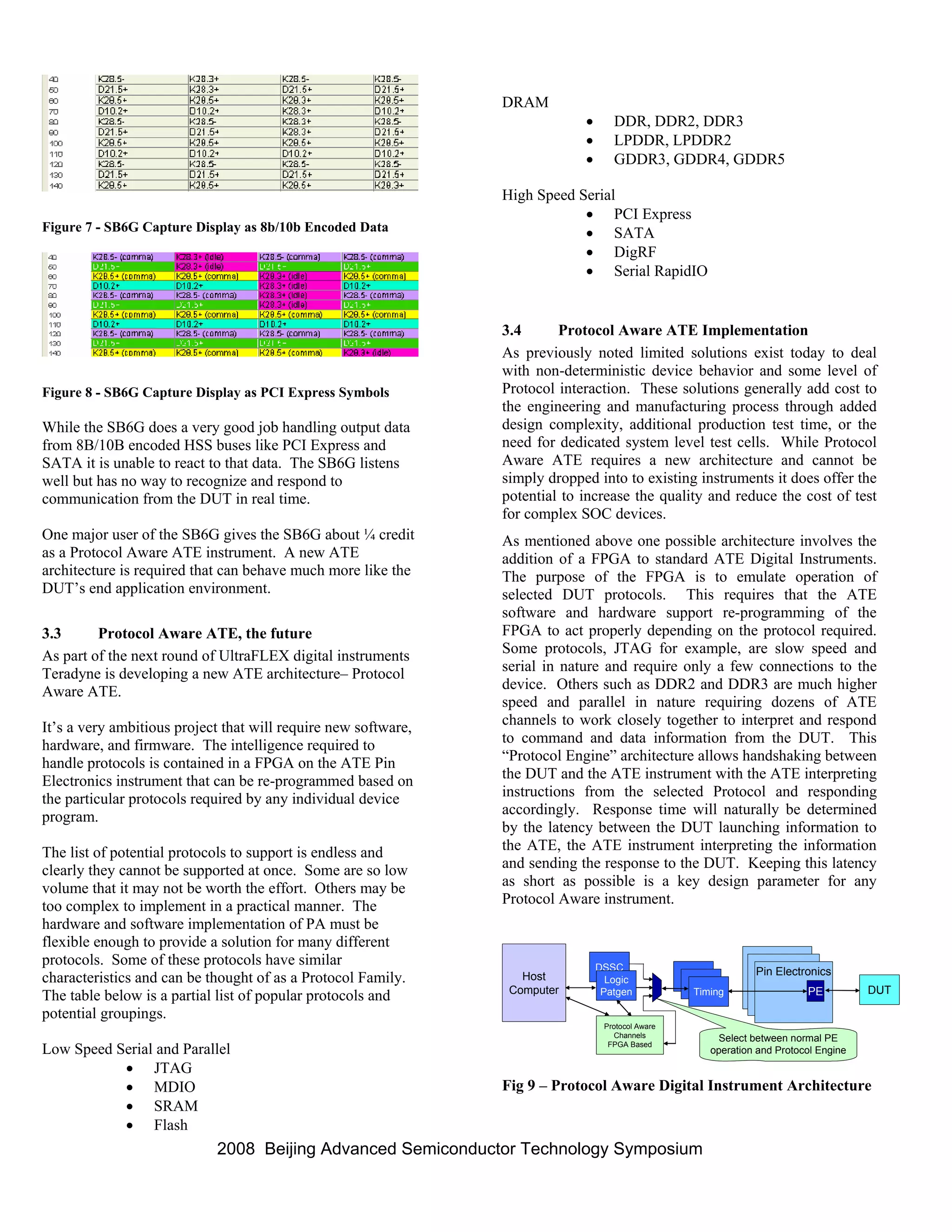
1. Modern semiconductor devices often behave in a non-deterministic manner during testing on automatic test equipment (ATE) due to the use of asynchronous IP blocks and industry standard protocols.
2. Current ATE architectures assume deterministic behavior and have difficulty handling variations in timing and output order, resulting in long test times and inadequate fault coverage.
3. A proposed solution is a protocol aware ATE that can natively emulate real-time chip I/O at the protocol level, enabling more complete functional testing similar to "mission mode" operation.
DFT (design for testability) is a technique that facilitates making a design testable after production by adding extra logic during the design process. This extra logic helps with post-production testing. DFT is needed because manufacturing processes are not perfect and can introduce defects. Methods like adding scan chains are used, where scanned flip-flops are connected in series to form a shift register and improve controllability and observability for testing. Common fault models tested for include stuck-at faults, where a line is stuck at either a 0 or 1 value due to defects introduced during manufacturing.
This document discusses VLSI testing and analysis. It defines key terms like defect, fault, and error and describes typical types of defects. It also discusses logical fault models and the role of testing in quality control. Different types of tests like production testing and burn-in testing are described. The testing process, fault simulation, design for testability techniques, and built-in self-test are summarized.
Formal verification is the process of proving or disproving properties of a system using precise mathematical methods. It provides guarantees that no simulations will violate specified properties. Formal verification can be applied at the block and system-on-chip levels to eliminate bugs early. However, current formal verification tools have limitations including capacity issues, generating coverage metrics from assertions, and handling large designs and multiple modes of operation. Improving formal verification requires efficient strategies and advancing tool capabilities.
The document provides an overview of the ASIC design and verification process. It discusses the key stages of ASIC design including specification, high-level design, micro design, RTL coding, simulation, synthesis, place and route, and post-silicon validation. It then describes the importance of verification, including why 70% of design time and costs are spent on verification. The verification process uses testbenches, directed and constrained-random testing, and functional coverage to verify the design matches specifications. Verification of more complex designs like FPGAs, SOCs is also discussed.
The document discusses formal verification academic research in the UK. It outlines several universities and research groups conducting work in formal methods and verification, including the Universities of Cambridge, Warwick, Oxford, Bristol, and Southampton. It also summarizes a verification methodology paper co-authored by researchers from the University of Oxford and Intel that addresses issues like realism, structure, and debugging in microprocessor design verification.
Soo Ang has over 30 years of experience in semiconductor test engineering. She has extensive experience developing test programs for memory chips like SRAM, DRAM, and Flash memory on various test systems. Currently she is a Senior Staff Test Engineer at Marvell validating memory IP chips. She is proficient in test development, product engineering, debugging, and ensuring test coverage.
The document discusses lessons learned from testing object-oriented systems. It covers the state of the art in object-oriented test design, automation, and representation. It also examines the state of the practice, finding that the best organizations implement systematic testing at multiple scopes from classes to subsystems. With rigorous testing following design patterns, world-class quality below 0.025 defects per function point is achievable.
The document describes the key stages of the software testing life cycle (STLC), including contract signing, requirement analysis, test planning, test development, test execution, defect reporting, and product delivery. It provides details on the processes, documents, and activities involved in each stage. Risk analysis and bug/defect management processes are also summarized. Various test metrics and bug tracking tools that can be used are listed.
Dependable Systems -Fault Tolerance Patterns (4/16)Peter Tröger
The document discusses various patterns for achieving fault tolerance in dependable systems. It covers architectural patterns like units of mitigation and error containment barriers. It also discusses detection patterns such as fault correlation, system monitoring, acknowledgments, voting, and audits. Finally, it discusses error recovery patterns like quarantine, concentrated recovery, and checkpointing to avoid data loss during recovery. The patterns provide reusable solutions for commonly occurring problems in building fault tolerant systems.
This document discusses reverse code engineering and the process involved. It provides an introduction by the speaker, Krishs Patil, who has a master's degree in computer application and is a computer programmer, reverser, and security researcher. The outline covers the reversing process, tools and techniques, reversing in different contexts, a lab demonstration, and defeating reverse engineering. It delves into the reversing process including defining scope, setting up environment, disassembling vs decompiling, program structure, and knowledge required. It also covers assembly language, system calls, portable executable files, and analysis tools. The overall document provides an in-depth overview of reverse engineering concepts, approaches, and skills needed.
The document discusses in-system programming (ISP) and the WriteNow! series of ISP programmers. ISP allows programming of devices while installed on printed circuit boards, improving manufacturing efficiency. The WriteNow! programmers enable fast, parallel programming of multiple devices simultaneously using various protocols. They can operate standalone or integrated with automatic test equipment. Features include custom data programming, encryption, and an easy-to-use interface.
Software testing involves checking if actual results match expected results to ensure a system is defect-free. It is important because software bugs can be expensive or dangerous, as demonstrated by examples where software failures caused monetary losses, human injuries or deaths. There are different types of testing like functional, non-functional, and maintenance testing, as well as different testing strategies like black box, white box, unit, integration, system, and acceptance testing. Test cases are documents used to verify requirements through test data, preconditions, expected results, and post conditions for a specific test scenario.
Dependable Systems -Dependability Means (3/16)Peter Tröger
This document provides an overview of dependability and dependable systems. It defines dependability as the trustworthiness of a system such that reliance can be placed on the service it delivers. The key aspects of dependability discussed include fault prevention, fault tolerance, fault removal, and fault forecasting. Fault tolerance techniques aim to provide service even in the presence of faults through methods like redundancy, error detection, error processing through recovery, and fault treatment. Dependable system design involves assessing risks, adding redundancy, and designing error detection and recovery capabilities.
Through four use cases with examples, we describe how IEEE 1687 can be extended to include analog and mixed-signal chips, including linkage to circuit simulators on one end of the ecosystem and ATE on the other. The role of instrumentation, whether on the tester or on the device itself, is central to analog testing, and conveniently also the focal point of IEEE 1687. We identify enhancements to the modular netlist and test languages (ICL and PDL) to facilitate the description of the components involved in analog tests as well as the content of the tests themselves.
The document discusses challenges in designing low power speech processing systems-on-chip (SoCs). It outlines C-DAC's focus on low power applications and describes their ASTRA portfolio of IPs. It then covers various low power design techniques like clock gating, power gating, voltage and frequency scaling. The document concludes by describing C-DAC's NAADA speech processor SoC that integrates these techniques and achieves less than 5mW power consumption.
Formal verification refers to mathematical techniques for specifying, designing, and verifying software and hardware systems. It involves proving or disproving the correctness of algorithms in a system with respect to a formal specification or property using formal methods of mathematics. Formal verification techniques include manual proofs, semi-automatic theorem proving, and automatic algorithms that take a model and property to determine if the model satisfies the property. Formal verification is commonly used for safety-critical systems like embedded systems to help ensure correctness. Tools like VC formal, VC LP, and Spyglass can be used to formally verify designs early in development without complex test benches or stimulus.
Semiconductor test engineering is the process of screening semiconductor devices to remove defective parts before shipment. This is done through testing to detect defects rather than prove the devices work as intended. The goal is to ensure high quality by catching manufacturing defects. If untested devices were shipped, many faulty ones could reach customers. Test engineering develops programs and hardware to efficiently test large volumes of devices in parallel while subjecting them to stress conditions to reveal marginal defects. It is important for achieving high yield and low cost.
Dependable Systems - Hardware Dependability with Redundancy (14/16)Peter Tröger
1) The document discusses hardware dependability through the use of redundancy. It provides examples of static redundancy like voting and N-modular redundancy as well as dynamic redundancy using techniques like back-up sparing and duplex systems.
2) IBM's zSeries mainframe computers are highlighted as an example of a highly redundant system, using techniques like machine check handling, error correction codes, unit deletion for degradation, and fully redundant I/O subsystems.
3) Redundancy comes at a cost but can effectively improve reliability through techniques that either mask faults or allow systems to reconfigure around faults. The level of redundancy must be weighed against associated costs and design complexity.
'Acceptance Test Driven Development Using Robot Framework' by Pekka Klarch & ...TEST Huddle
Acceptance test driven development (ATDD) is an important agile practice merging requirement gathering with acceptance testing. In its core are concrete examples, created together with the team, that provide collaborative understanding and, as automated acceptance tests, make sure that the features are implemented correctly. There are many ways to create ATDD examples/tests, and the behavior driven development (BDD) style with Given-When-Then format is one of the more popular ones.
Robot Framework is an open source test automation framework suitable for ATDD and acceptance testing in general. It has a flexible test data syntax that supports keyword-driven, data-driven, and BDD styles, but is still simple enough so that also non-programmers can create and understand test cases. The simple test library API makes extending the framework easy, and there are several ready made libraries that allow testing generic interfaces such as web, databases, Swing, SWT, Windows GUIs, Flex, and SSH out-of-the-box.
This presentation gives an introduction both to ATDD and Robot Framework. It contains different demonstrations and
all the material will be freely available after the presentation.
1. The document discusses software quality and reliability in engineering. It defines quality as software being bug-free, on time, meeting requirements, and maintainable. Reliability is the probability of failure-free operation over time in a given environment.
2. Ensuring quality involves preventing and detecting faults during all phases of the software development life cycle from requirements to testing. The V-model helps achieve quality by involving testers early on.
3. Reliability focuses on avoiding faults during design and detecting problems during all phases through techniques like fault tolerance, forecasting, and measuring metrics like MTBF.
This document discusses context-driven test automation and describes four common contexts for automation: individual developer, development team, project, and product line. It analyzes two case studies - the ITE and xBVT test automation frameworks - and how they address common test automation tasks like distribution, setup/teardown, execution, verification and reporting differently depending on their context. The key lesson is that the approach that works best depends on who writes and uses the tests rather than a one-size-fits-all framework. Defining the context upfront helps determine how automation tasks are implemented.
The document discusses testbenches, which are virtual environments used to verify design correctness. A testbench provides stimulus and verifies responses. Developing a testbench is important and time-consuming. Testbenches need to balance goals like reusability, efficiency and flexibility while considering practical concerns. The document outlines topics like testbench components, development approaches, and requirements.
This document provides an overview of dependability and dependable systems. It defines dependability as an umbrella term that includes reliability, availability, maintainability, and other attributes that allow systems to be trusted. Dependability addresses how systems can continue operating correctly even when faults occur. Key topics covered include fault tolerance techniques, error processing, failure modes, and modeling approaches for analyzing dependability. The goal of the course is to understand how to design systems that can be relied upon to deliver their services as specified, even in the presence of faults or unexpected events.
The document discusses software testing, including definitions of software testing, the testing process involving test selection, execution, oracles, and adequacy, and types of testing such as unit testing, integration testing, system testing, stress testing, and performance testing. It also provides examples of levels of testing from the unit to system level and discusses testing the EasyLine system composed of multiple subsystems.
This presentation describes the history and background behind the introduction of model checking. Transition systems workflow is also illustrated in terms of model checking.
This document provides a summary of Quentin Pierce's experience and qualifications. It outlines his 16 years of experience designing both hardware circuits and software tools to support hardware design. Some of his hardware experience includes designing digital interface boards and I/O boards. His software experience includes API programming and static code checking of hardware description language code. He provides several examples of projects he has worked on, skills utilized, and outcomes, ranging from designing printer and interface circuits to writing linting rules and automation scripts. Overall, the document presents Quentin as a senior engineer with extensive experience in both hardware and software design across various consumer product and test equipment domains.
This document describes ATE test services offered in China at significantly lower costs than in the US. Engineering hourly and weekly rates are 50% lower, and turn-key test solutions including test planning, debugging, programming, and production support are available. Customized solutions can further reduce costs for production testing through techniques like dedicated test modules that minimize loadboard layers and ATE instruments needed.
IC Test Handlers Industry ConsolidationWilliam Huo
The document discusses consolidation before and after some event. It seems to compare two different situations or states related to consolidation, with one coming before and the other coming after whatever event triggered the change in state. Unfortunately there are no other details provided in the document to give more specific context about what is being consolidated or what event caused the change.
The document discusses the benefits of protocol aware automatic test equipment (ATE) compared to traditional ATE. Protocol aware ATE would allow testers to interact with devices under test using the same protocol level of abstraction as designers, making testing easier and reducing development cycles. It provides examples showing how protocol aware ATE could speed up silicon bring-up and debug by enabling direct register reads and writes using protocols instead of low-level vectors. This would help address issues of non-deterministic device behavior from processes like cycle slipping.
The document describes Cogent ATE's Leopard A Series Analog and Mixed-Signal Test System. It aims to provide low-cost, high-performance multi-site testing through its Floating Quad-Site Testing architecture. This allows independent testing of up to 4 devices simultaneously while avoiding interference through electrically isolated test sites. The system supports a wide range of analog and mixed-signal devices and can scale from single-site to multi-site testing through its Automatic Test Replication technology.
Track g semiconductor test program - testinsightchiportal
This document discusses challenges in semiconductor testing and opportunities to improve test program management. It identifies issues such as lack of visibility into what is tested in production and which test program versions are used. It then proposes several solutions like enabling collaborative test development, enforcing company test methodologies, analyzing and merging test programs, and closing the loop between test program development and production to improve quality.
This document discusses quantifying shmoo plot results by defining a metric called Shmoo Quality (SQ). SQ is defined as the area of the pass region in a shmoo plot. Quantifying SQ allows direct comparison of shmoo plots and trend analysis of SQ over time or process variations. An example is given where SQ is calculated for shmoo plots of three golden devices before and after changes, demonstrating up to 163% improved SQ. Quantifying shmoo results provides benefits for product and test engineering.
Automated hardware testing system using Python. The system includes an embedded test hardware module that can measure voltage, current, resistance and test protocols. Python scripts control the hardware, run test cases, collect results and generate reports. This provides a low-cost automated solution compared to expensive automated test equipment. Test reports show pass/fail results and help locate hardware and software issues.
A pattern is a collection of data that precisely describes the activity of each tester pin at bus clock resolution. It is generated from a test simulation trace and is specific to each tester. A pattern contains pindefs, vecdefs, vectors, comments and labels. Pindefs define the connection between pattern data and tester channels. Vecdefs define the sequences for each pin. Vectors contain the actual tester data for each period. Comments provide information and labels allow jumping to specific points. Patterns contain reset/initialization routines, the test pattern itself with multiple vectors, and subroutine memory.
The document compares different types of testers used for debugging components, including S9K, IMS Vanguard, and CWMA testers, describing their key features such as speed, operating system, memory size, and capabilities for timing, patterns, and levels of testing. It also provides overviews of tester channel connections, functional test content and tools, and terms and definitions used for testing.
This document describes several engineering roles involved in the chip design process. An Analog Design Engineer designs the analog portion of chips, which requires power operations. A Digital Design Engineer designs the digital logic of chips. A Design Verification Engineer checks designs for bugs to ensure proper functioning. A Physical Design Engineer turns designs into a geometric format for manufacturing. A Validation Engineer tests physical hardware to ensure it functions as intended. A Firmware Engineer develops software that runs on hardware to enable its intended functions.
This document describes test development services provided by SEM, including structural and functional testing. SEM has 15+ years of experience in test engineering and can support various industries. Services include in-circuit testing, boundary scan testing, optical inspection, X-ray inspection, and flying probe testing using equipment from Agilent, Teradyne, Goepel, and others. SEM also develops customized functional test solutions and provides turnkey test systems for applications like IT equipment, communications devices, consumer products, and more.
Challenges in Assessing Single Event Upset Impact on Processor SystemsWojciech Koszek
Abstract—This paper presents a test methodology developed at Xilinx for real-time soft-error rate testing as well as the software framework in which Device-Under-Test (DUT) and controlling computer are both synchronized with the proton beam controls and run experiments automatically in a predictable manner. The method presented has been successfully used for Zynq®-7000 All Programmable SoC testing at the UC Davis Crocker Nuclear Lab. Presented are the issues and challenges encountered during design and implementation of the framework, as well as lessons learned from the in-house experiments and bootstrapping tests performed with Thorium Foil. The method presented has helped Xilinx to deliver high-quality experimental data and to optimize time spent in the testing facility.
Keywords—Error detection, soft error, architectural vulnerability, statistical error, confidence level, beam facility control
DESIGN APPROACH FOR FAULT TOLERANCE IN FPGA ARCHITECTUREVLSICS Design
Failures of nano-metric technologies owing to defects and shrinking process tolerances give rise to significant challenges for IC testing. In recent years the application space of reconfigurable devices has grown to include many platforms with a strong need for fault tolerance. While these systems frequently contain hardware redundancy to allow for continued operation in the presence of operational faults, the need to recover faulty hardware and return it to full functionality quickly and efficiently is great. In addition to providing functional density, FPGAs provide a level of fault tolerance generally not found in mask-programmable devices by including the capability to reconfigure around operational faults in the field. Reliability and process variability are serious issues for FPGAs in the future. With advancement in process technology, the feature size is decreasing which leads to higher defect densities, more sophisticated techniques at increased costs are required to avoid defects. If nano-technology fabrication are applied the yield may go down to zero as avoiding defect during fabrication will not be a feasible option Hence, feature architecture have to be defect tolerant. In regular structure like FPGA, redundancy is commonly used for fault tolerance. In this work we present a solution in which configuration bit-stream of FPGA is modified by a hardware controller that is present on the chip itself. The technique uses redundant device for replacing faulty device and increases the yield.
One of the key benefits of JTAG is that it provides access to the internal circuitry of a device without the need for additional hardware such as a test probe or emulator. This is possible because JTAG uses a series of test access ports (TAPs) that are built into a device's boundary-scan architecture.
JTAG
https://www.corelis.com/education/tutorials/jtag-tutorial/jtag-test-overview/
JTAG is an integrated method for testing interconnects on printed circuit boards (PCBs) that are implemented at the integrated circuit (IC) level.
George Bates has over 20 years of experience in the IT and telecommunications fields. He has extensive expertise in networking, IP technologies, and mobility products integration and testing. Currently he works as the Transport Test Lead for Alcatel-Lucent, leading testing of small cell features and Ethernet, IPv4, IPv6, and IPsec transport. Previously he held roles testing LTE, CDMA, and EVDO technologies and networks. He has a proven track record of managing projects, resolving complex issues, and training others.
Joseph Alvarez has over 10 years of experience as an IC development engineer and design verification engineer at ROHM LSI Design Philippines, where he is involved in all stages of IC product development from design to manufacturing and has worked on projects including various memory chips and display drivers. He holds a Bachelor's degree in Electronics and Communications Engineering from Don Bosco Technical College and is skilled in using EDA tools from Cadence and Synopsys for simulation, layout, and verification. In his free time, he enjoys music, boxing, and spending time with his family.
https://www.corelis.com/education/tutorials/jtag-tutorial/what-is-jtag/
JTAG allows for the testing and programming of digital and analog circuits, including microprocessors, memory devices, and other digital and mixed-signal components.
#JTAG
Boundary scan has become an indispensable technology as engineers like you face increasing test challenges. Agilent is proud to introduce the new x1149 Boundary Scan Analyzer - bringing the best of our technology and vast test experience - to your workbench!
1) Computer simulation is becoming more popular for studying induction heating processes as it provides developers with information about what is happening in the system to help optimize processes more effectively than experimental trial and error.
2) The document presents a case study using computer simulation to optimize induction heating of a difficult to heat axle fillet area. 1D and 2D simulations were used initially, followed by a 2D coupled electromagnetic and thermal simulation.
3) Parameters like frequency, coupling gap, and use of a magnetic flux concentrator were varied in the simulations to achieve uniform heating of the fillet area and obtain the desired hardened zone profile. The simulations helped determine optimal coil design and operating conditions.
This resume summarizes Gene Cernilli's experience as a senior engineering professional with expertise in telecom and military electronics systems design. Over 30 years of experience includes roles in embedded systems design, PCB layout, FPGA design, software development, and project engineering. He has worked on projects for companies such as Alcatel-Lucent, Aviat Networks, Qualcomm, and Ultra Electronics, leading development of products like optical network terminals, sonar systems, and medical devices.
The document discusses using electronic system level (ESL) design methodology to validate hardware/software functionality, performance, and power requirements above the register-transfer level (RTL). It describes how ESL transaction-level models can be reused at the RTL block level and system integration phases using emulation. ESL allows validating software integration earlier and reducing RTL verification effort by finding bugs earlier in the design cycle. The document also provides an example of using an ARM Cortex-A9 transaction-level platform for virtual prototyping and software integration.
This document discusses four approaches to improving Linux performance in embedded multicore devices: 1) the Linux PREEMPT_RT patch set, which replaces kernel spinlocks with mutexes to improve real-time responsiveness but can reduce throughput; 2) LWRT, which partitions Linux into real-time and non-real-time domains to avoid using the kernel and improves both real-time performance and throughput; 3) the Open Event Machine, which partitions Linux and runs some processes on a non-Linux runtime; and 4) hypervisors or "thin kernels", which add a real-time kernel underneath Linux. The document focuses on explaining LWRT and how it compares to PREEMPT_RT in improving both real
Michael J. Ledford has a Bachelor of Science in Computer Engineering and Electrical Engineering from North Carolina State University. He has experience in hardware and software design, verification, and testing roles at Qualcomm, Intel, and Cisco. His skills include SystemVerilog, Perl/Python scripting, hardware debugging, and signal integrity analysis. He is looking for a role as a system hardware/software designer and tester in the consumer electronics industry.
- Kenneth L. Feken has over 20 years of experience in electronics assembly, testing, and troubleshooting. He has worked for companies like Intel, CDTI, Tektronix, and Laerdal Medical Supply where he performed tasks like circuit board assembly, soldering, testing, reworking, and quality control.
- He has an Associate's Degree in Electrical Engineering Technology from ITT Technical Institute where he gained skills in engineering, programming, software, and testing.
- Currently, he is looking for a position where he can utilize his extensive experience in electronics assembly, circuit board work, software testing, and troubleshooting.
Ethercat.org industrial ethernet technologiesKen Ott
This document provides an overview of various industrial ethernet technologies. It divides the technologies into three classes - Class A uses standard ethernet hardware and TCP/IP, Class B uses standard hardware but a dedicated process data protocol, and Class C uses dedicated hardware for high performance. The document then summarizes key aspects of several industrial ethernet technologies, including PROFINET, comparing their performance, capabilities and limitations.
This document provides an overview of industrial Ethernet technologies, comparing their technical principles and performance capabilities. It divides the technologies into three classes - Class A uses standard Ethernet hardware and TCP/IP, Class B uses custom protocols but standard hardware, and Class C uses dedicated hardware for highest performance. The document then examines several technologies, particularly analyzing the different versions and capabilities of PROFINET.
Similar to 2008 Asts Technical Paper Protocol Aware Ate Submitted (20)
How to Interpret Trends in the Kalyan Rajdhani Mix Chart.pdfChart Kalyan
A Mix Chart displays historical data of numbers in a graphical or tabular form. The Kalyan Rajdhani Mix Chart specifically shows the results of a sequence of numbers over different periods.
Skybuffer AI: Advanced Conversational and Generative AI Solution on SAP Busin...Tatiana Kojar
Skybuffer AI, built on the robust SAP Business Technology Platform (SAP BTP), is the latest and most advanced version of our AI development, reaffirming our commitment to delivering top-tier AI solutions. Skybuffer AI harnesses all the innovative capabilities of the SAP BTP in the AI domain, from Conversational AI to cutting-edge Generative AI and Retrieval-Augmented Generation (RAG). It also helps SAP customers safeguard their investments into SAP Conversational AI and ensure a seamless, one-click transition to SAP Business AI.
With Skybuffer AI, various AI models can be integrated into a single communication channel such as Microsoft Teams. This integration empowers business users with insights drawn from SAP backend systems, enterprise documents, and the expansive knowledge of Generative AI. And the best part of it is that it is all managed through our intuitive no-code Action Server interface, requiring no extensive coding knowledge and making the advanced AI accessible to more users.
Taking AI to the Next Level in Manufacturing.pdfssuserfac0301
Read Taking AI to the Next Level in Manufacturing to gain insights on AI adoption in the manufacturing industry, such as:
1. How quickly AI is being implemented in manufacturing.
2. Which barriers stand in the way of AI adoption.
3. How data quality and governance form the backbone of AI.
4. Organizational processes and structures that may inhibit effective AI adoption.
6. Ideas and approaches to help build your organization's AI strategy.
Your One-Stop Shop for Python Success: Top 10 US Python Development Providersakankshawande
Simplify your search for a reliable Python development partner! This list presents the top 10 trusted US providers offering comprehensive Python development services, ensuring your project's success from conception to completion.
Best 20 SEO Techniques To Improve Website Visibility In SERPPixlogix Infotech
Boost your website's visibility with proven SEO techniques! Our latest blog dives into essential strategies to enhance your online presence, increase traffic, and rank higher on search engines. From keyword optimization to quality content creation, learn how to make your site stand out in the crowded digital landscape. Discover actionable tips and expert insights to elevate your SEO game.
HCL Notes und Domino Lizenzkostenreduzierung in der Welt von DLAUpanagenda
Webinar Recording: https://www.panagenda.com/webinars/hcl-notes-und-domino-lizenzkostenreduzierung-in-der-welt-von-dlau/
DLAU und die Lizenzen nach dem CCB- und CCX-Modell sind für viele in der HCL-Community seit letztem Jahr ein heißes Thema. Als Notes- oder Domino-Kunde haben Sie vielleicht mit unerwartet hohen Benutzerzahlen und Lizenzgebühren zu kämpfen. Sie fragen sich vielleicht, wie diese neue Art der Lizenzierung funktioniert und welchen Nutzen sie Ihnen bringt. Vor allem wollen Sie sicherlich Ihr Budget einhalten und Kosten sparen, wo immer möglich. Das verstehen wir und wir möchten Ihnen dabei helfen!
Wir erklären Ihnen, wie Sie häufige Konfigurationsprobleme lösen können, die dazu führen können, dass mehr Benutzer gezählt werden als nötig, und wie Sie überflüssige oder ungenutzte Konten identifizieren und entfernen können, um Geld zu sparen. Es gibt auch einige Ansätze, die zu unnötigen Ausgaben führen können, z. B. wenn ein Personendokument anstelle eines Mail-Ins für geteilte Mailboxen verwendet wird. Wir zeigen Ihnen solche Fälle und deren Lösungen. Und natürlich erklären wir Ihnen das neue Lizenzmodell.
Nehmen Sie an diesem Webinar teil, bei dem HCL-Ambassador Marc Thomas und Gastredner Franz Walder Ihnen diese neue Welt näherbringen. Es vermittelt Ihnen die Tools und das Know-how, um den Überblick zu bewahren. Sie werden in der Lage sein, Ihre Kosten durch eine optimierte Domino-Konfiguration zu reduzieren und auch in Zukunft gering zu halten.
Diese Themen werden behandelt
- Reduzierung der Lizenzkosten durch Auffinden und Beheben von Fehlkonfigurationen und überflüssigen Konten
- Wie funktionieren CCB- und CCX-Lizenzen wirklich?
- Verstehen des DLAU-Tools und wie man es am besten nutzt
- Tipps für häufige Problembereiche, wie z. B. Team-Postfächer, Funktions-/Testbenutzer usw.
- Praxisbeispiele und Best Practices zum sofortigen Umsetzen
Unlock the Future of Search with MongoDB Atlas_ Vector Search Unleashed.pdfMalak Abu Hammad
Discover how MongoDB Atlas and vector search technology can revolutionize your application's search capabilities. This comprehensive presentation covers:
* What is Vector Search?
* Importance and benefits of vector search
* Practical use cases across various industries
* Step-by-step implementation guide
* Live demos with code snippets
* Enhancing LLM capabilities with vector search
* Best practices and optimization strategies
Perfect for developers, AI enthusiasts, and tech leaders. Learn how to leverage MongoDB Atlas to deliver highly relevant, context-aware search results, transforming your data retrieval process. Stay ahead in tech innovation and maximize the potential of your applications.
#MongoDB #VectorSearch #AI #SemanticSearch #TechInnovation #DataScience #LLM #MachineLearning #SearchTechnology
In the rapidly evolving landscape of technologies, XML continues to play a vital role in structuring, storing, and transporting data across diverse systems. The recent advancements in artificial intelligence (AI) present new methodologies for enhancing XML development workflows, introducing efficiency, automation, and intelligent capabilities. This presentation will outline the scope and perspective of utilizing AI in XML development. The potential benefits and the possible pitfalls will be highlighted, providing a balanced view of the subject.
We will explore the capabilities of AI in understanding XML markup languages and autonomously creating structured XML content. Additionally, we will examine the capacity of AI to enrich plain text with appropriate XML markup. Practical examples and methodological guidelines will be provided to elucidate how AI can be effectively prompted to interpret and generate accurate XML markup.
Further emphasis will be placed on the role of AI in developing XSLT, or schemas such as XSD and Schematron. We will address the techniques and strategies adopted to create prompts for generating code, explaining code, or refactoring the code, and the results achieved.
The discussion will extend to how AI can be used to transform XML content. In particular, the focus will be on the use of AI XPath extension functions in XSLT, Schematron, Schematron Quick Fixes, or for XML content refactoring.
The presentation aims to deliver a comprehensive overview of AI usage in XML development, providing attendees with the necessary knowledge to make informed decisions. Whether you’re at the early stages of adopting AI or considering integrating it in advanced XML development, this presentation will cover all levels of expertise.
By highlighting the potential advantages and challenges of integrating AI with XML development tools and languages, the presentation seeks to inspire thoughtful conversation around the future of XML development. We’ll not only delve into the technical aspects of AI-powered XML development but also discuss practical implications and possible future directions.
Let's Integrate MuleSoft RPA, COMPOSER, APM with AWS IDP along with Slackshyamraj55
Discover the seamless integration of RPA (Robotic Process Automation), COMPOSER, and APM with AWS IDP enhanced with Slack notifications. Explore how these technologies converge to streamline workflows, optimize performance, and ensure secure access, all while leveraging the power of AWS IDP and real-time communication via Slack notifications.
HCL Notes and Domino License Cost Reduction in the World of DLAUpanagenda
Webinar Recording: https://www.panagenda.com/webinars/hcl-notes-and-domino-license-cost-reduction-in-the-world-of-dlau/
The introduction of DLAU and the CCB & CCX licensing model caused quite a stir in the HCL community. As a Notes and Domino customer, you may have faced challenges with unexpected user counts and license costs. You probably have questions on how this new licensing approach works and how to benefit from it. Most importantly, you likely have budget constraints and want to save money where possible. Don’t worry, we can help with all of this!
We’ll show you how to fix common misconfigurations that cause higher-than-expected user counts, and how to identify accounts which you can deactivate to save money. There are also frequent patterns that can cause unnecessary cost, like using a person document instead of a mail-in for shared mailboxes. We’ll provide examples and solutions for those as well. And naturally we’ll explain the new licensing model.
Join HCL Ambassador Marc Thomas in this webinar with a special guest appearance from Franz Walder. It will give you the tools and know-how to stay on top of what is going on with Domino licensing. You will be able lower your cost through an optimized configuration and keep it low going forward.
These topics will be covered
- Reducing license cost by finding and fixing misconfigurations and superfluous accounts
- How do CCB and CCX licenses really work?
- Understanding the DLAU tool and how to best utilize it
- Tips for common problem areas, like team mailboxes, functional/test users, etc
- Practical examples and best practices to implement right away
Salesforce Integration for Bonterra Impact Management (fka Social Solutions A...Jeffrey Haguewood
Sidekick Solutions uses Bonterra Impact Management (fka Social Solutions Apricot) and automation solutions to integrate data for business workflows.
We believe integration and automation are essential to user experience and the promise of efficient work through technology. Automation is the critical ingredient to realizing that full vision. We develop integration products and services for Bonterra Case Management software to support the deployment of automations for a variety of use cases.
This video focuses on integration of Salesforce with Bonterra Impact Management.
Interested in deploying an integration with Salesforce for Bonterra Impact Management? Contact us at sales@sidekicksolutionsllc.com to discuss next steps.
GraphRAG for Life Science to increase LLM accuracyTomaz Bratanic
GraphRAG for life science domain, where you retriever information from biomedical knowledge graphs using LLMs to increase the accuracy and performance of generated answers
Introduction of Cybersecurity with OSS at Code Europe 2024Hiroshi SHIBATA
I develop the Ruby programming language, RubyGems, and Bundler, which are package managers for Ruby. Today, I will introduce how to enhance the security of your application using open-source software (OSS) examples from Ruby and RubyGems.
The first topic is CVE (Common Vulnerabilities and Exposures). I have published CVEs many times. But what exactly is a CVE? I'll provide a basic understanding of CVEs and explain how to detect and handle vulnerabilities in OSS.
Next, let's discuss package managers. Package managers play a critical role in the OSS ecosystem. I'll explain how to manage library dependencies in your application.
I'll share insights into how the Ruby and RubyGems core team works to keep our ecosystem safe. By the end of this talk, you'll have a better understanding of how to safeguard your code.
Introduction of Cybersecurity with OSS at Code Europe 2024
2008 Asts Technical Paper Protocol Aware Ate Submitted
1. Protocol Aware ATE
Eric Larson
Teradyne
30701 Agoura Road
Agoura Hills, Calif USA 91301
Biography 1. Introduction
Eric Larson has more than 28 years of experience
SOC device operation is often non-deterministic in the end
working at Teradyne in roles ranging from Factory
application (mission mode). Devices seamlessly
Applications Engineer to Field Product Specialist, and
communicate and handshake to establish operating
Technical Marketing. Eric has been involved with
parameters such as data timing and operating frequency.
supporting Teradyne’s Logic and SOC test systems
This capability, while perfectly acceptable and necessary in
from J283 through Catalyst and UltraFLEX. He
the customer application can cause serious problems during
currently works in the Broadband, Computing, and
ATE test. Among the reasons for non-deterministic
Storage (BCS) Business Unit focusing on Digital
behavior in a test environment are:
testing, both high speed and DFT.
- Multiple time domains with no frequency relationship
Abstract:
- Asynchronously linked buses with an independent PLL
Modern semiconductor devices often behave in a non-
per time domain
deterministic manner not only in their end application but
- I/O buses using many different complex protocols and
during test execution on ATE as well. This is the result of
clocking schemes
design methodologies that allow the assembly of the device
- Different behavior across Process, Voltage, and
from a library of IP blocks. These IP blocks often support
Temperature (PVT) including shifts in timing, insertion
specific industry standard protocols such as JTAG, DDR
of idle cycles, and changes in data order
memory buses, PCI Express, etc. While the operation of any
individual block may be predictable the timing relationship
Current stored response ATE architectures can only deal
between protocols often is not. Today’s SOC ATE does not
with deterministic behavior during test. As a result
deal well with ambiguity. Any deviation from expected
device behavior will cause that device to fail ATE test, both
- Test development time is long because of the
during engineering development or production.
difference in Device Under Test (DUT) behavior in
Functionally testing devices that exhibit non-deterministic
design and ATE
behavior is extremely difficult on current generation ATE.
- Fault coverage is inadequate because the DUT is not
This paper describes a proposed solution to deal with non- tested in “Mission Mode” (end application)
deterministic device behavior, a new ATE architecture - - Test times are long because multiple pattern
Protocol Aware ATE (PA-ATE). Specifically covered will executions are required looking for a pass or the DUT
be some of the problems currently faced by Semiconductor output must be captured and post-processed
ATE users and the usefulness of Protocol Aware ATE to - Early silicon yield is reduced because good devices
address those problems. don’t match ATE pass conditions
As described by Andy Evans of Broadcom, protocol Aware
This problem is becoming more pervasive. The
ATE is an:
semiconductor design community has a rich set of
“ATE Architecture which can natively emulate real time proprietary and commercial tools available to simplify and
chip I/O at the Protocol Level. speed up device design.
Enables testing a device [with methods] ranging from using
- Design teams develop full feature designs faster using
a single chip interface to total “Mission Mode”, at the
Asynchronous IP that speeds design time and chip
highest level of abstraction centric to the interfaces specific
timing closure
protocols.” [1]
- Designers work with high level behavioral simulations,
simplifying verification of complex bus protocols.
The test community is not so fortunate
- Test Engineers do not have re-usable Test IP
2008 Beijing Advanced Semiconductor Technology Symposium
2. - Behavioral level simulations (event based) must be can deal with the handshaking and non-deterministic device
converted to vectors (time based). Test engineers must behavior described above.
debug with low level vectors - ’01HLX’.
- Asynchronous Interfaces cause non-determinism, ATE users are not so fortunate. Variations in processing,
which test engineers must try to predict and adjust for voltage, or temperature can change the timing of DUT
in the timing and vectors (may shift with Process output data and in some cases even the order in which data
Variation). occurs. This non-determinism can occur not only from
device-to-device but from test to test in the same device.
The device design methodology and behavior described There are cases where no pattern will pass 100% of the time
above causes a number of problems for the test community. on today’s deterministic ATE. It’s not uncommon to run a
pattern multiple times and treat the device as good if it
When operating in the end application (mission mode) passes even once.
many devices require some sort of interaction to:
2. Dealing with DUT Non-Determinism
- Establish communication parameters such as bus speed
and width.
2.1 Today’s test compromises
- Set up internal register states for proper operation
In order to deal with unpredictable device behavior during
- Load up internal memory (SRAM, DRAM or Flash)
ATE test a few strategies can be employed, some apply to
with information required for the device to properly
the device design itself and some to the test techniques used.
operate, sometimes referred to as boot code
As part of initial design, device operation can be artificially
This device-to-device interaction often involves two-way
constrained in several ways to help force deterministic
handshaking. One device will send information and wait
behavior. Test structures can be added to the device:
for the other device to respond. The exact amount of time it
takes for this operation is not critical since the specific
- To partition the design for structural test (Scan)
Protocol will dictate what to send and how long to wait for
- To control clocks for delay fault testing (AC Scan)
the response. This non-deterministic behavior is perfectly
- To synchronize time domains
acceptable in mission-mode operation but poses major
- So the device can test/repair itself
problems for test on ATE.
o Memory Built-In Self Test (MBIST)
o Logic Built-In Self Test (LBIST)
Even for designs using robust Design For Testability (DFT)
methodology, non-deterministic behavior can occur during
To support test on ATE, test strategies can be constrained in
ATE test. One example is Memory Built-In Self Test
several ways to compensate for non-deterministic behavior:
(MBIST) where the device design incorporates circuitry to
test and perhaps repair embedded memory arrays. After
- Eliminate problematic tests
initialization and becoming activated, the MBIST controller
- Test only one portion of the device at a time
will operate independently and provide results to ATE once
- Limit test speed to increase likelihood of deterministic
the test is complete. The ATE must recognize when data is
behavior
available and capture all the failure information provided by
- Mask (ignore) non-deterministic portions of test
the DUT. Depending on the device failure mechanism and
vectors
desired data (pass/fail, data for bitmapping or redundancy
- Run patterns multiple times to increase the likelihood
analysis) both the amount of fail data and the time at which
of detecting a pass
that data is made available to the ATE can vary across
MBIST engines within a single device. If testing multiple
devices in parallel each device response will be different. The result of the above constraints in device behavior and
Existing SOC ATE systems are not architected to deal well test strategies is a relatively well defined and measurable
with these differences in DUT behavior and must generally coverage of several classes of faults. Assuming properly
capture much more data than actually required just to constructed test structures and vectors, reasonable fault
ensure that no critical information is missed. coverage can be achieved for some fault types including:
First silicon bring-up is usually a parallel effort with teams - Stuck-at, bridging, or open faults
working on bench equipment and ATE. The bench setup - Delay faults that are large enough to be detected with
usually consists of a PC controlling the DUT through AC scan
standard debug ports like JTAG and a selection of - Transition faults
instruments each dedicated to particular Protocol. It is quite
common to get the device running much quicker on the Other faults such as those listed below may be fortuitously
bench than on ATE since communication with bench detected by the techniques described above. There is much
instruments occurs at a Protocol level. Bench instruments ongoing work to create fault models and detection
are designed to emulate real-world device operation so they techniques for these types of faults to improve both actual
fault coverage and the associated metrics. The current state
2008 Beijing Advanced Semiconductor Technology Symposium
3. of the art is just that, part evolving science and part art. “Topping off” DFT and structural test fault coverage with
Among the faults that may (or may not) be detected by tests at-speed functional testing, sometimes referred to as
designed to force deterministic behavior are: “Mission-Mode” test, is viewed by many semiconductor
manufacturers as necessary to achieve the low (sub-
- Resistive bridging faults and cross-coupling 100DPM) defect rates required by their customers. Because
capacitance faults that cause different effects on path it is “Hard to emulate (the) functional environment with a
delays with different input patterns standalone chip” Cisco’s current plan includes adding BIST
- Delay faults dependent on the global/local activity at system level test to help catch and identify failures
within the device. missed on ATE.
- Transient or soft errors introduced by noise like supply
IR-drop, ground bounce, or Ldi/dt Some semiconductor manufacturers have focused on a
- Leaky gates heavily DFT based test strategy. While still using DFT as
a key portion of their test strategy other manufacturers are
clearly of the opinion that some form of at-speed functional
2.2 Fault Coverage – DFT versus Mission Mode
testing is required to deliver high quality products.
As seen in table 1 below, at the 2007 VLSI Test
Symposium one ASIC manufacturer (IBM) defined At-speed functional test of semiconductor devices can be
reasonable fault coverage. [2] accomplished at several steps in the manufacturing process.
- 99% stuck-at faults (DC start/DC end) If supported by the device design and behavior can be made
- 85% transition faults (Scan/ASST/TADT) predictable, production test on ATE can be expanded to
cover at-speed faults. In many other cases a commonly
implemented solution is to design active components into
the ATE Device Interface Board (DIB). These components
can include DRAM’s to help test DDR buses, Flash devices
to act as Boot memory, a Field Programmable Gate Array
(FPGA) to mimic digital circuitry found in the end
application, or TX/RX devices to support handshaking over
high speed serial buses. While useful for adding fault
coverage to ATE test insertions these active devices add
design and manufacturing complexity to the DIB,
increasing cost and reducing reliability.
In cases where achieving adequate fault coverage cannot be
accomplished today on ATE it may be required to
Table 1 - ASIC Fault Coverage
temporarily inserting the DUT into a test fixture that
emulates the functional environment of the final system
At the same conference a major ASIC customer (Cisco)
application. Often referred to as System Level Test (SLT),
presented a view of the impact of test, particularly test
this is an additional step in the manufacturing flow and
escapes, on ASIC faults.[3] Almost 70% of the ASIC
requires separate test and handling equipment. While the
failures found at system test were attributed to ATE test
SLT equipment is usually less expensive per test cell than
escapes.
SOC ATE systems, throughput and productivity is usually
much lower. In addition the SLT is normally very
dedicated and is applicable only to a single, high volume
device design. Because of the additional cost, both in
equipment and test time, use of SLT is generally avoided
whenever possible.
A third alternative is to wait until the device is in the final
application. This is certainly the least desirable and most
expensive of the alternatives due to the high cost of
replacing the defective component once assembled in the
final product, whether a $30 DVD player or a $50K
automobile.
A strategy of driving at-speed functional test coverage back
into ATE would seem to be cost effective relative to waiting
until the system is assembled to identify the problems.
Figure 1 - ASIC Failures at system test Without Protocol Aware capability, today’s ATE cannot
easily support that strategy.
2008 Beijing Advanced Semiconductor Technology Symposium
4. bench can involve multiple people and organizations if
2.3 Bench versus ATE
attempted on ATE. The simple example of modifying a
As mentioned above it’s quite common for new devices to
MDIO write instruction can require a very complex edit to
be brought up on both ATE and in a Bench Validation
the pattern file and likely require a re-simulation. Turn-
environment. Using PC’s to debug the processor though
around time for a re-simulation can be hours because of the
some host interface such as JTAG, PCI or a dedicated
number of steps required and the need to move away from
debug bus often has basic functionality working in minutes.
the ATE and into the simulation environment.
In many cases the device comes up much faster on the
bench than on ATE since the bench process uses high level
An additional problem occurs if the test engineer needs
language and instruments targeted for specific IP blocks and
assistance from the design or validation community.
protocols. Functional coverage can be achieved on the
Design engineers don’t generally deal well with ATE
bench in minutes that could take weeks (or forever) on ATE.
specific pattern languages and test engineers are not
particularly conversant at the transaction level. This creates
In the bench environment it’s easy to identify and modify
a language barrier that makes debugging difficult.
instructions and data sent to the device. Written in high
level code, the simulation environment is easily ported to At one semiconductor manufacturer it’s very common to
the bench. If the engineer wants to change the contents of a have the test engineer debugging a problem in ATE terms
particular internal register it’s a simple matter of creating a and the designer sitting right next to them with the
transaction that sends a “write” instruction in the chosen simulation information displayed on their laptop. The
protocol. If the contents need to be examined a “read” process of matching ATE results to simulation is very error
transaction will return the contents in the proper format. An prone and time consuming. Two widely divergent views of
example of a series (or set) of MDIO transactions appears the problem in two separate computing environments is not
below courtesy of Broadcom. conducive to efficient problem solving.
Silicon debug can be so difficult that some ATE users have
resorted to hooking external instruments to their Device
Interface Boards. They use a JTAG Debugger costing less
than $3000USD (one example shown below) to solve the
problem that their $1,000,000USD SOC Automatic Test
Equipment cannot.[4]
Figure 2 – Protocol Transactions from Bench
The transactions are human readable and easy to interpret.
They can be created and modified quickly with a text editor
and immediately applied to the Device Under Test.
Once translated to run on ATE all resemblance to the
original high level transaction set is lost. It is difficult, if
BDI1000 High-speed BDM/JTAG Debug Interface
not impossible, to differentiate between instruction and data
since all information is contained in ATE pattern files and ABATRON AG
expressed as a series of vectors containing 10HLMX
BDM support for CPU12/16/32/32+, PowerPC, 5xx/8xx, ColdFire
characters. Picture the difficulty of finding and modifying
the data for a specific MDIO write transaction in the ATE JTAG support for ARM, M-CORE, PowerPC 4xx, MIPS32
pattern below.
Figure 4 – JTAG Protocol Debugger Example
A properly implemented Protocol Aware solution will
allow the SOC ATE users to create and use transaction
level language as easily on ATE as on the bench. One SOC
ATE user has specifically identified that adding protocol
aware features to next generation testers is critical for
maintaining the rapid product development cycle that has
brought them success. An initial estimate is that these
problems cost them 50-60 days of extra work on each new
device. A separate conversation with a major Graphics
Processor manufacturer valued every week shaved from
silicon bring-up and debug at $10M in the market.
Figure 3 – SOC ATE Test pattern
Because of the radically different levels of abstraction 3. Protocol Aware ATE
between simulation language and ATE test patterns, an
operation that takes a one engineer a few seconds on the 3.1 Protocol Aware ATE, the history
2008 Beijing Advanced Semiconductor Technology Symposium
5. and other ATE instruments are capable of Clock Data
Protocol Aware ATE is not a new concept, several Recovery (CDR) on High Speed Serial buses. This
semiconductor manufacturers have asked for similar c- functionality is critical for dealing with non-deterministic
capability over the last few years. timing from the DUT. [5]
- Micro-Controller Manufacturer 2001 DUT Tx: Non-Deterministic Timing
One US-based Micro-Controller manufacturer described
• Clock Recovery and Phase Tracking Per Lane
non-deterministic device behavior as caused by the
• CDR circuit recovers DUT embedded
combination of high speed packet based protocols and Jitter / Eye
Jitter / Sample
clock & centers ATE strobe
internal asynchronous boundaries. They also noted that Eye Processing
Sampler
Compare
• CDR circuit continually tracks
simulation can provide deterministic patterns but defect-free Vector data
Align
Timing &
Data Compare PRBS
Data Eye and adjusts strobe ATE Receiver
silicon may behave differently than simulation. Specifically Auto-seed
Compare Out-
they asked for a HW/SW solution to analyze data streams at of Order Data
a higher level than bits. A software methodology was Receive Align Trigger
developed to capture and post-process DUT output data. Disparity
CDR 10b Align 20b Match
& Symbol
Map RAM
…
While this technique worked well enough to determine Idle Data1+ Data2-
…
whether the device was operating correctly several hundred Data1+ Data2- Data1- Data2+
10b 10b 10b 10b 10b
10b
milliseconds were added to production test times. boundary boundary boundary boundary boundary
boundary
Data1+ Idle Data2-
…
DUT Output … …
…
…
Data2- Idle Data1+
Start
20b 20b Match
CDR Lock 10b 10b Match
- Micro-Processor Manufacturer 2001 RAT
Time RAT
Expect Pattern Begins Execution
Hold-Off
Hold-Off
A major Micro-Processor manufacturer identified a trend Figure 5 - SB6G & non-deterministic Timing
toward multiple independent clock-embedded interfaces
that would require enhancements to a traditional digital Both the SB6G and other ATE instruments can wait for a
functional test environment that would support non- specific set of data to be sent from the DUT before
deterministic timing behavior displayed by these interfaces. comparing for proper output, thus handling the ambiguity
They also identified the potential need to synchronize with associated with exactly when real data appears from the
multiple independent serial ports in a single pattern DUT. Additionally the SB6G can selectively ignore data
execution. packets such as Idle Cycles that may be injected in the
middle of legitimate data streams. [6]
- High-End SOC manufacturer 2002
In 2002 a high-end SOC manufacturer pointed out that
multi-bus devices have out-of-order data even at low
DUT Tx: Non-Deterministic Data Order
frequencies. Simulation predicts one sequence of events
• Symbol Map and Signature Generator per lane
but the device may behave differently. They must run the
• Symbol Map filters incoming DUT data
device and see if it works as expected. If not it is necessary
• Remaps an incoming 10b symbol
to keep moving around the ATE input and output timing to a different 10b symbol (Disparity) Jitter / Eye
Jitter / Sample
until the device works. This is a very time consuming Eye Processing
• Prevents an incoming 10b symbol Sampler
Compare
process in an engineering environment and impossible for Vector data
from being sent to Sig Gen Align
Timing &
Data Compare PRBS
• Signature Generator is a set of ATE Receiver
production test. Auto-seed
LFSR’s that accumulate the filtered data Compare Out-
of Order Data
• Signature Generator output
- Micro-Processor Manufacturer 2003 Pin Input Output Send to Description
used to determine pass/fail Symbol Symbol SigGen
In 2003 a major Micro-Processor manufacturer described a TXA Disparity- Disparity+ Enable Remap all disparity
…
need for comm-like ATE capability for characterization. Idle Data1+ Data2-
TXA K28.5- Disable Disable symbol from being sent to SG
…
The motivation was unique interfaces that had complex Data1+ Data2- Data1- Data2+
TXA K28.5+ Disable Disable symbol from being sent to SG
handshaking protocols. In order to be stable the protocols Data1+ Idle Data2-
TXA D31.7+ D31.7- Enable Remap one symbol to another
required a synchronization handshake since they allowed Data2- Idle Data1+
non-deterministic behavior in the end application.
Figure 6 - SB6G & non-deterministic Data
The SB6G also has the ability to capture the DUT output
3.2 Protocol Aware ATE today for later analysis. To better understand what the DUT is
actually doing a specially written software tool can show
As previously noted, ATE today generally deals poorly with
the captured output as either low-level data or in Protocol
unpredictable device behavior. There are exceptions,
terms at a higher level of abstraction.
particularly in the High Speed Serial (HSS) area for those
protocols using 8b/10b encoded data. Architected in 2003,
the 6.4Gbps SB6G from Teradyne can deal with some types
of ambiguity coming from the Device Under Test (DUT).
Other ATE vendors have also introduced instruments
designed to test high speed serial buses. Both the SB6G
2008 Beijing Advanced Semiconductor Technology Symposium
6. DRAM
• DDR, DDR2, DDR3
• LPDDR, LPDDR2
• GDDR3, GDDR4, GDDR5
High Speed Serial
• PCI Express
Figure 7 - SB6G Capture Display as 8b/10b Encoded Data • SATA
• DigRF
• Serial RapidIO
3.4 Protocol Aware ATE Implementation
As previously noted limited solutions exist today to deal
with non-deterministic device behavior and some level of
Protocol interaction. These solutions generally add cost to
Figure 8 - SB6G Capture Display as PCI Express Symbols
the engineering and manufacturing process through added
design complexity, additional production test time, or the
While the SB6G does a very good job handling output data
need for dedicated system level test cells. While Protocol
from 8B/10B encoded HSS buses like PCI Express and
Aware ATE requires a new architecture and cannot be
SATA it is unable to react to that data. The SB6G listens
simply dropped into to existing instruments it does offer the
well but has no way to recognize and respond to
potential to increase the quality and reduce the cost of test
communication from the DUT in real time.
for complex SOC devices.
One major user of the SB6G gives the SB6G about ¼ credit As mentioned above one possible architecture involves the
as a Protocol Aware ATE instrument. A new ATE addition of a FPGA to standard ATE Digital Instruments.
architecture is required that can behave much more like the The purpose of the FPGA is to emulate operation of
DUT’s end application environment. selected DUT protocols. This requires that the ATE
software and hardware support re-programming of the
FPGA to act properly depending on the protocol required.
3.3 Protocol Aware ATE, the future
Some protocols, JTAG for example, are slow speed and
As part of the next round of UltraFLEX digital instruments
serial in nature and require only a few connections to the
Teradyne is developing a new ATE architecture– Protocol
device. Others such as DDR2 and DDR3 are much higher
Aware ATE.
speed and parallel in nature requiring dozens of ATE
channels to work closely together to interpret and respond
It’s a very ambitious project that will require new software,
to command and data information from the DUT. This
hardware, and firmware. The intelligence required to
“Protocol Engine” architecture allows handshaking between
handle protocols is contained in a FPGA on the ATE Pin
the DUT and the ATE instrument with the ATE interpreting
Electronics instrument that can be re-programmed based on
instructions from the selected Protocol and responding
the particular protocols required by any individual device
accordingly. Response time will naturally be determined
program.
by the latency between the DUT launching information to
the ATE, the ATE instrument interpreting the information
The list of potential protocols to support is endless and
and sending the response to the DUT. Keeping this latency
clearly they cannot be supported at once. Some are so low
as short as possible is a key design parameter for any
volume that it may not be worth the effort. Others may be
Protocol Aware instrument.
too complex to implement in a practical manner. The
hardware and software implementation of PA must be
flexible enough to provide a solution for many different
protocols. Some of these protocols have similar DSSC Pin Electronics
characteristics and can be thought of as a Protocol Family. Host T
Logic
T
Computer DUT
PE
Patgen Timing
The table below is a partial list of popular protocols and
potential groupings.
Protocol Aware
Channels Select between normal PE
FPGA Based
Low Speed Serial and Parallel operation and Protocol Engine
• JTAG
• MDIO Fig 9 – Protocol Aware Digital Instrument Architecture
• SRAM
• Flash
2008 Beijing Advanced Semiconductor Technology Symposium
7. -
In addition to emulating the desired Protocol, the Reduce/eliminate system level test
instrument must also support classic Digital ATE test requirements
functionality such as Scan, DFT, functional test, and
characterization. The user must be able to select between DIB COMPLEXITY/COST/RELIABILITY
- Reduce/eliminate “Golden Device”
“normal” and Protocol Aware operation during both
- Reduce/eliminate FLASH, DRAM, SERDES
engineering and production test.
devices on the DIB, particularly critical for
One key requirement for solving the “Bench versus ATE” multi-site test
problem introduced in section 2.3 is the ability to read and
write internal DUT registers in a simple and straightforward
manner, similar to the high level language used in
simulation and bench instruments. A properly implemented Improve
Reduce Pgm
Early
Develop &
Protocol Aware solution will allow the user to enter a read Silicon
Debug Time
Yield
or write command along with the associated address and Speed Up
Reduce
Silicon
payload data and have the DUT immediately respond. Test Time
Debug
Protocol
Aware
Re-creating sets of transactions from simulation or bench ATE
Reduce Reduce or
instrument on ATE will no longer require translation to the Customer
Customer Eliminate
Return System
low level language of ATE patterns. Debug Time Level Test
Improve
Fault Reduce DIB
Instead of appearing as a pseudo-random group of 1’s and Coverage Complexity
And DPM
0’s the DUT interaction will be at a high level of
abstraction. One possible syntax is shown below.
Time to Production
Quality
Protocol(MyMDIO).Send(mdio_frame_write, &01, &1f, &00F0)‘ MDIO block address Rx0 Market Economics
Protocol(MyMDIO).Recieve(mdio_frame_read_rang_compare, &01, anaRXStatus_A, &8000,&0000)` Read PRBS Error Count
Protocol(MyMDIO).Send(mdio_frame_write, &01, &1f, &0100)‘ MDIO block address Rx1
Protocol(MyMDIO).Recieve(mdio_frame_read_rang_compare, &01, anaRXStatus_A, &8000,&0000)` Read PRBS Error Count
Protocol(MyMDIO).Send(mdio_frame_write, &01, &1f, &00F0)‘ MDIO block address Rx2
Fig 11 – Protocol Aaware User Benefits [7]
Protocol(MyMDIO).Recieve(mdio_frame_read_rang_compare, &01, anaRXStatus_A, &8000,&0000)` Read PRBS Error Count
Protocol(MyMDIO).Send(mdio_frame_write, &01, &1f, &0100)‘ MDIO block address Rx3
Protocol(MyMDIO).Recieve(mdio_frame_read_rang_compare, &01, anaRXStatus_A, &8000,&0000)` Read PRBS Error Count
4. Limitations
Fig 10 – Protocol Aware Digital Instrument Architecture
Limitations come with every project and Protocol Aware
ATE is no exception. The most obvious issue is the huge
Dealing with the DUT with a higher level language, similar
and growing number of protocols. It is clear that not all
to the design environment will speed debug and reduce
protocols are created equal, either in ease of
time-to-market of new SOC devices.
implementation or popularity. Initial solutions will cover a
set of popular protocols with an expanded list available
over time.
3.5 What problems can Protocol Aware ATE
The speed of ATE PA engines is limited by a couple of bus
Potentially Address?
characteristics and ATE attributes. If the bus requires I/O
handshaking the round-trip delay of the pin electronics
TIME TO MARKET
along with processing time in the FPGA may limit speed to
- Faster bringup of early silicon
that of low speed protocols. Buses that do not require
- Faster debug of customer returns
handshaking can generally be supported up to much higher
- Faster correlation to bench instruments
speeds, limited by the fundamental operating frequency of
- Faster pattern generation, DUT native
the FPGA.
language
- Faster pattern debug, DUT native language
5. Discussion
- Real-time pattern debug, immediate mode
As detailed in section 3.5 above there are a number of areas
QUALITY where Protocol Aware ATE can provide benefits to ATE
- Better fault coverage thru Mission-Mode users. As with most new concepts the actual benefits will
become more obvious over time. Since PA ATE is still in
functional testing
it’s infancy we can really only speculate as to the long term
value to ATE users but a few things seem obvious.
PRODUCTION ECONOMICS (Test Time)
- Reduce/eliminate the need to capture and post-
- Broadcom has determined that Protocol Aware
process DUT output data
capability is the next architectural breakthrough in
- Eliminate re-running the pattern multiple
ATE and they are pushing both their suppliers and
times to find a pass
competitors to get on board.
- Fewer re-tests
2008 Beijing Advanced Semiconductor Technology Symposium
8. - Other Semiconductor Manufacturers are very capability applies to analog and mixed signal instruments as
interested in the concept well.
- Teradyne believes that Protocol Aware ATE has
tremendous value and is actively developing References:
solutions. [1] Andy Evans, Vision ATE 2020 at ITC 2007
[2] Vikram Iyengar et al, “An Integrated Framework for
- The concept is very compelling to many
At-speed and ATE-Driven Delay Test of Contract
semiconductor manufacturers because of the
Manufactured ASICs”, Proceedings VLSI Test
Time-To-Market issues that PA ATE can help
Symposium, 2007, Session 4B Paper 2
address
[3] Zoe Conroy, Bill Eklow, VLSI Test Symposium 2007,
Maybe not so obvious is the possibility of overstating Innovative Practices
Protocol Aware ATE as a general solution. Many ATE [4] Abatron AG Website
users have expressed interest in PA ATE as a replacement [5] Eric Larson, VLSI Test Symposium 2007, Innovative
for their current System Level Test (SLT) strategy. While Practices
PA ATE can certainly supplement and substitute for some [6] Eric Larson, VLSI Test Symposium 2007, Innovative
level of SLT it is doubtful that it will ever be a complete Practices
solution. Latency limitations described above will limit PA [7] Eric Larson, Kyoichi Sei, Teradyne User Group
ATE as a drop-in replacement for high speed DRAM on a Japan, November 2007
DIB. It is also clear that Protocol Aware ATE is
complementary to existing test techniques and Acknowledgments:
DFT/Structural test is still a necessary component of the Many colleagues have contributed to the pool of knowledge
overall test strategy. and opinion reflected in this document. In particular I
would like to recognize the teams that have been working
Conclusion:
closely with our lead customers for several months now to
Protocol Aware ATE is a new architecture and all
ensure we develop a product that fits the market need.
indications are that as a concept it is very appealing to a
broad set of ATE users, both existing and potential. - Teradyne’s Protocol Aware Hardware/Software/FPGA
Implemented properly PA ATE can provide immediate Design Team
payback by improving test development time and reducing - The Teradyne UltraFLEX Digital Tools Project Team
customer Time-To-Market. In the long run additional - Highly skilled ATE users at lead customers
benefits around better fault coverage will also become
apparent.
This concept signals a fundamental shift in SOC ATE
architecture. Future digital instruments will be designed to
be Protocol Aware. While starting with digital, PA
2008 Beijing Advanced Semiconductor Technology Symposium