Download to read offline

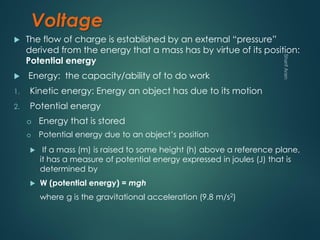
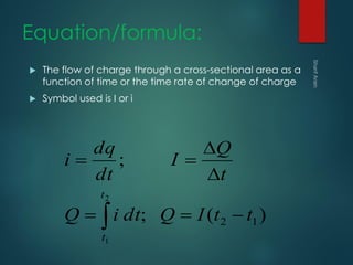
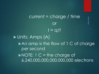
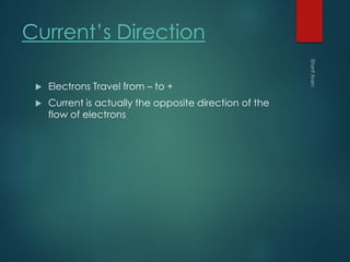
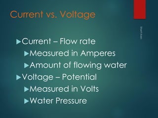
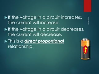
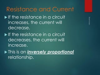
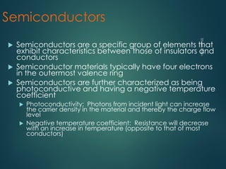
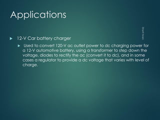


1. The document covers basic electrical concepts including circuits, charge, voltage, current, resistance, Ohm's law, conductors, insulators, semiconductors, and measurement devices. 2. Key concepts discussed include Kirchhoff's current and voltage laws, factors that influence resistance, and applications of electrical concepts like batteries and power supplies. 3. Engineering concepts such as resistivity of materials and its relationship to resistance through geometry are examined alongside historical scientists like Ohm, Ampere, and Volta who contributed to the field.


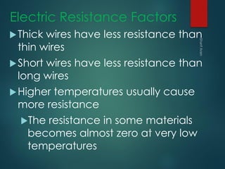
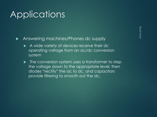
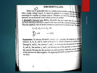
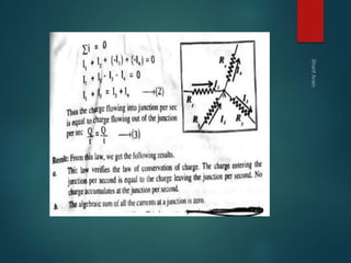
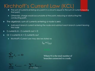
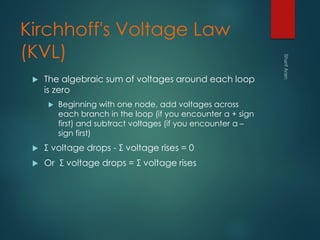
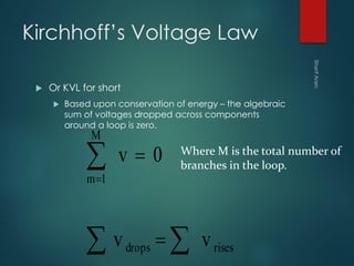
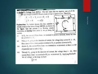
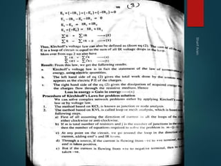
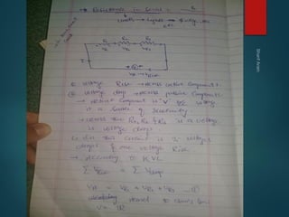
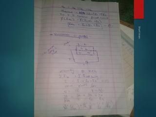
![Electric current, potential difference and reietance [Autosaved] [Autosaved]....](https://cdn.slidesharecdn.com/ss_thumbnails/electriccurrentpotentialdifferenceandreietanceautosavedautosaved-230603173933-3538dcc3-thumbnail.jpg?width=640&height=640&fit=bounds)


