Downloaded 230 times
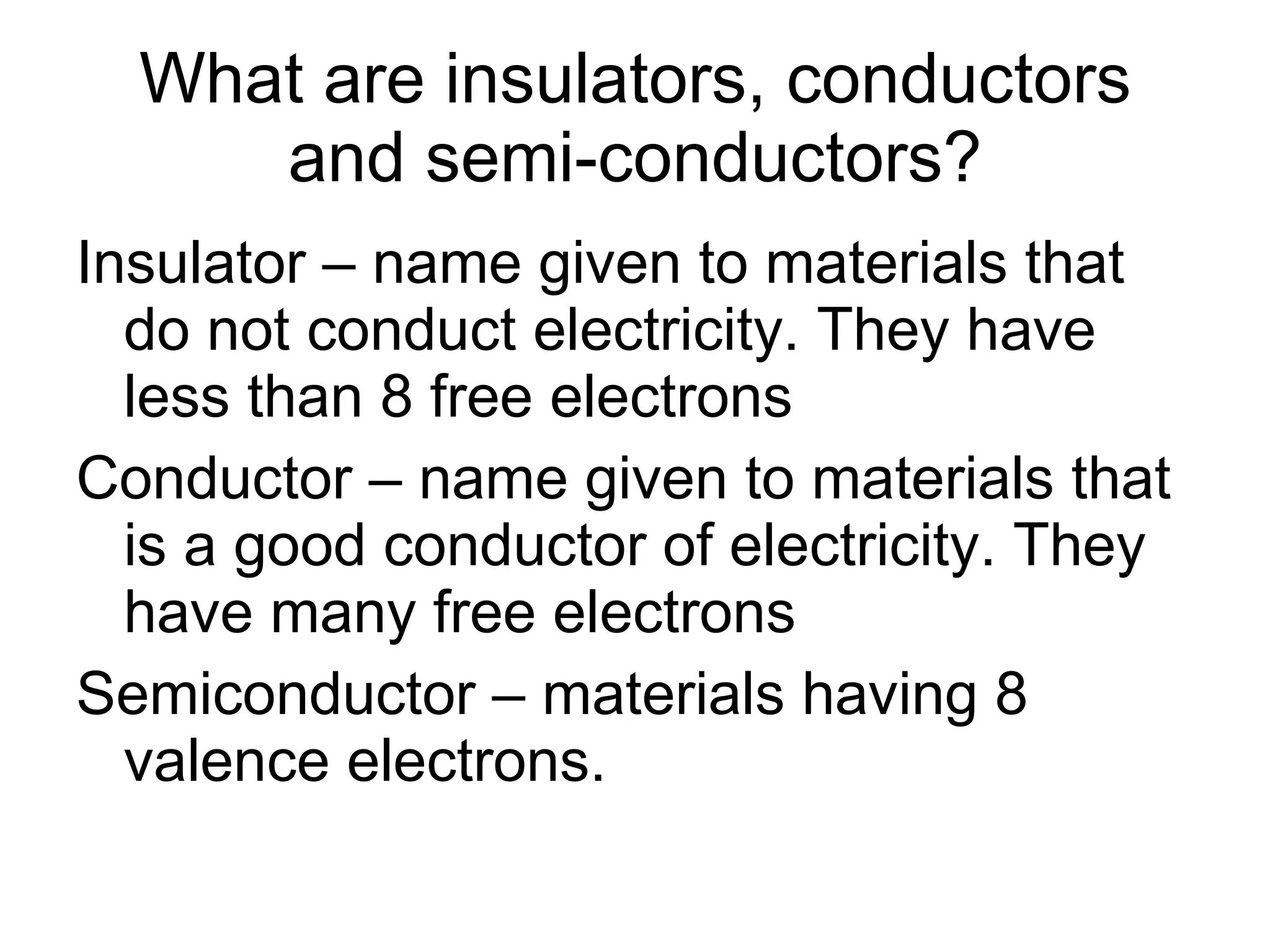
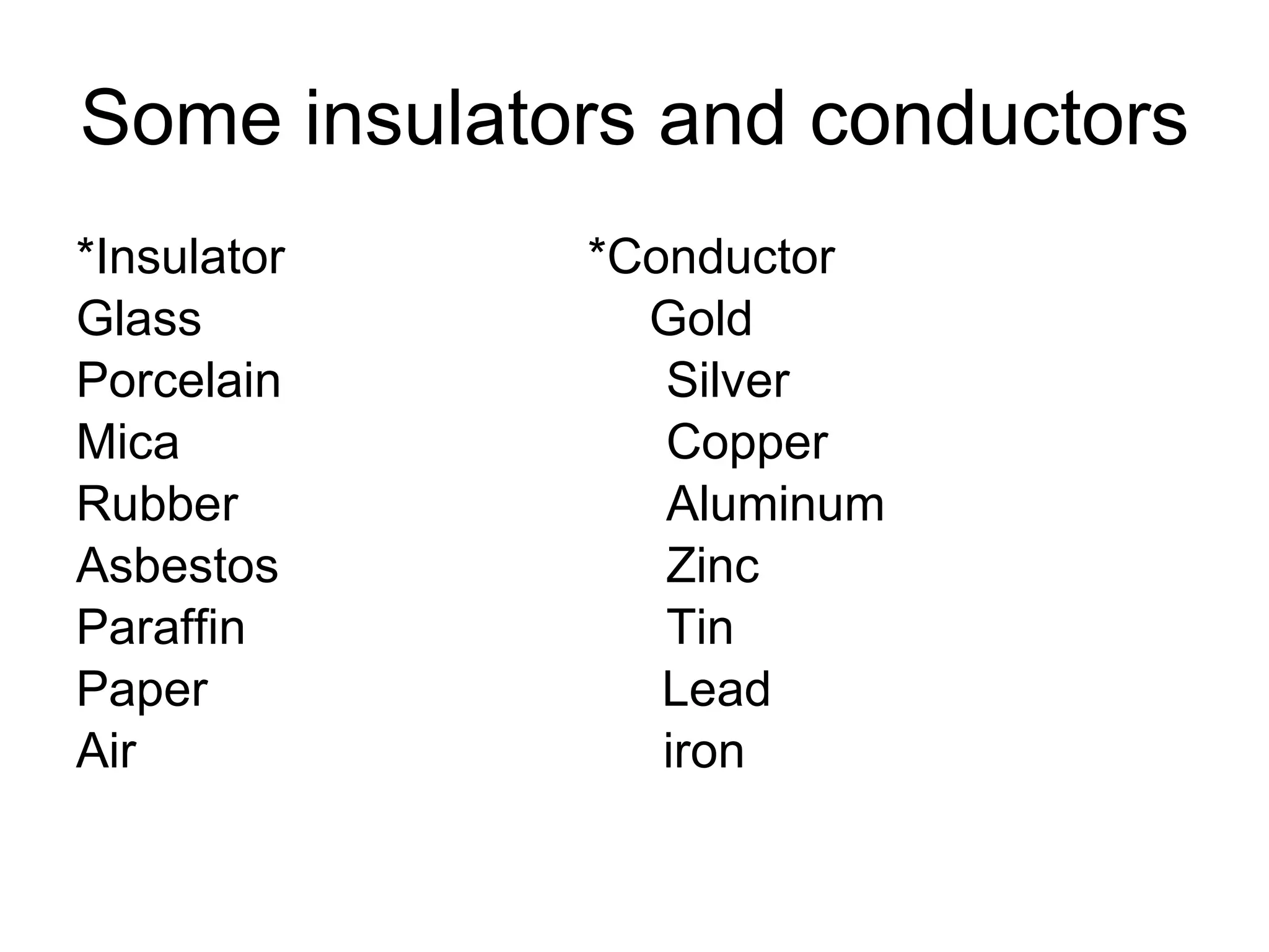
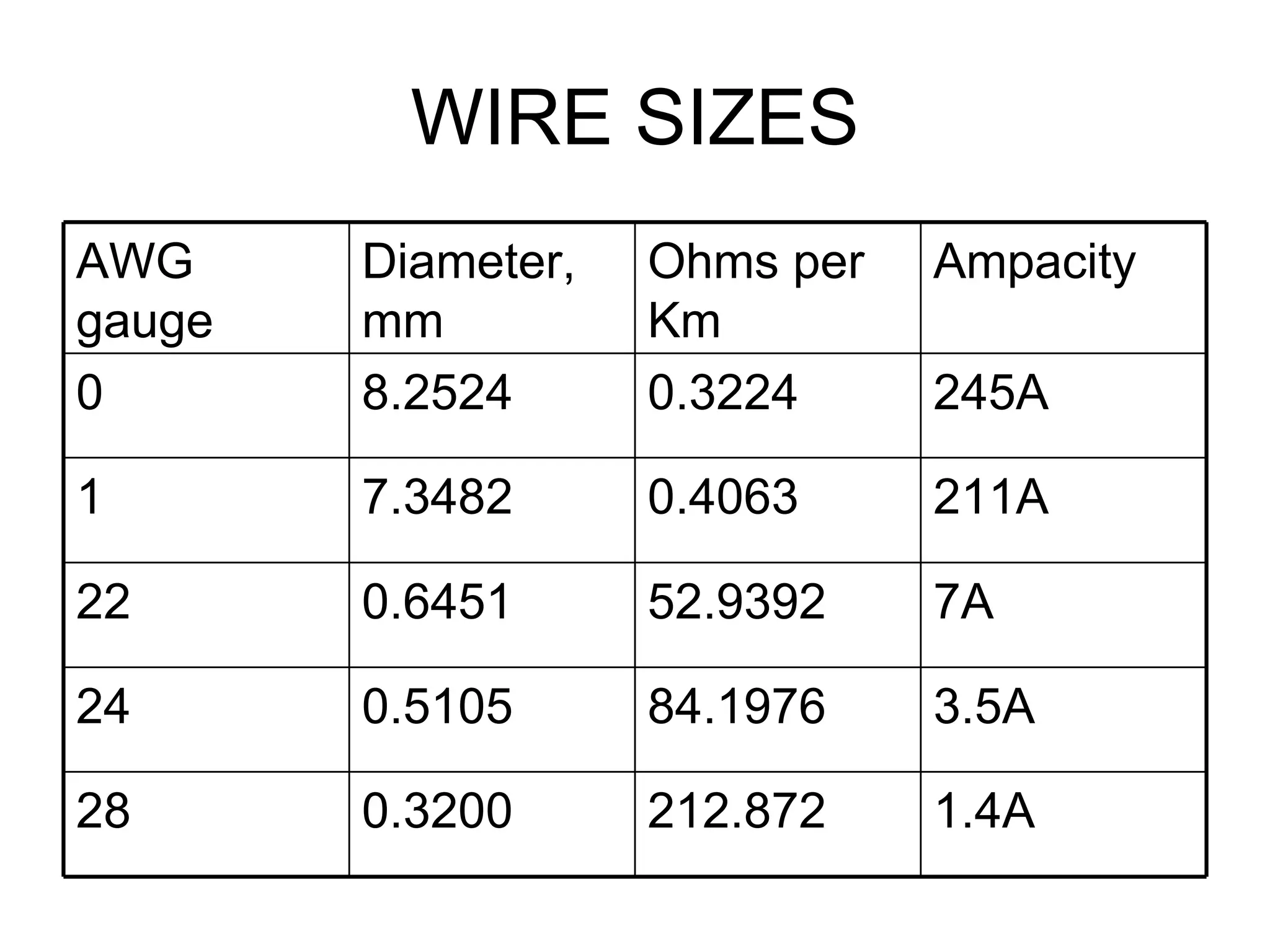
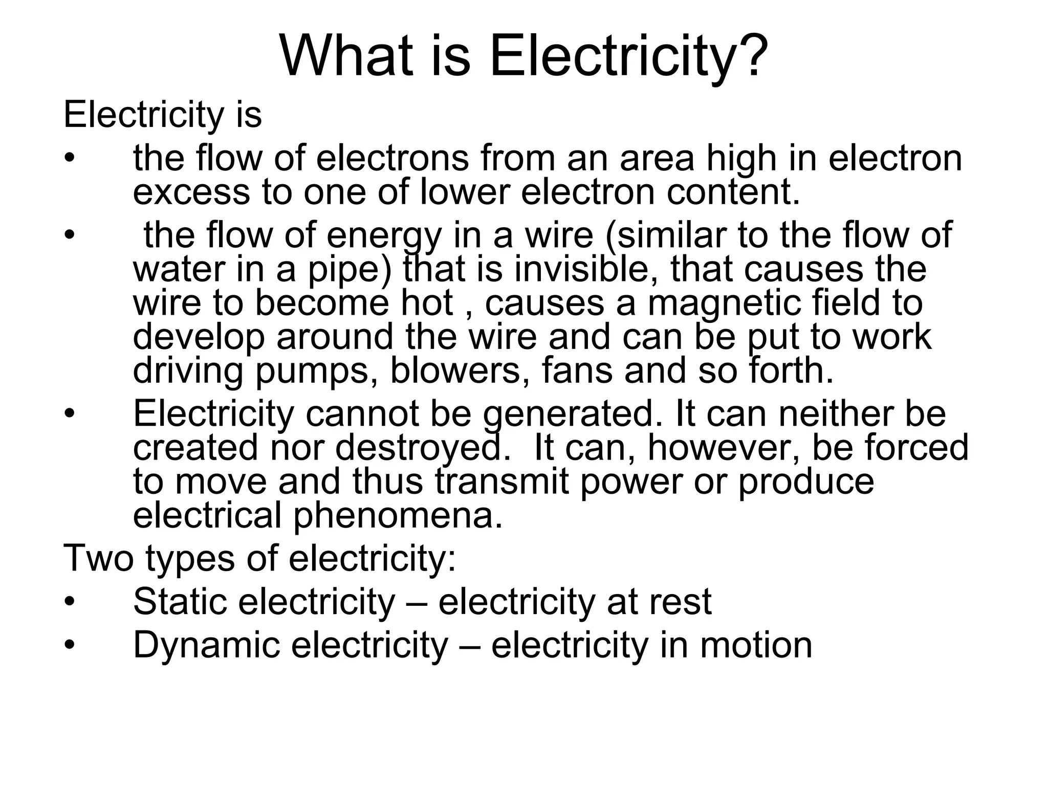

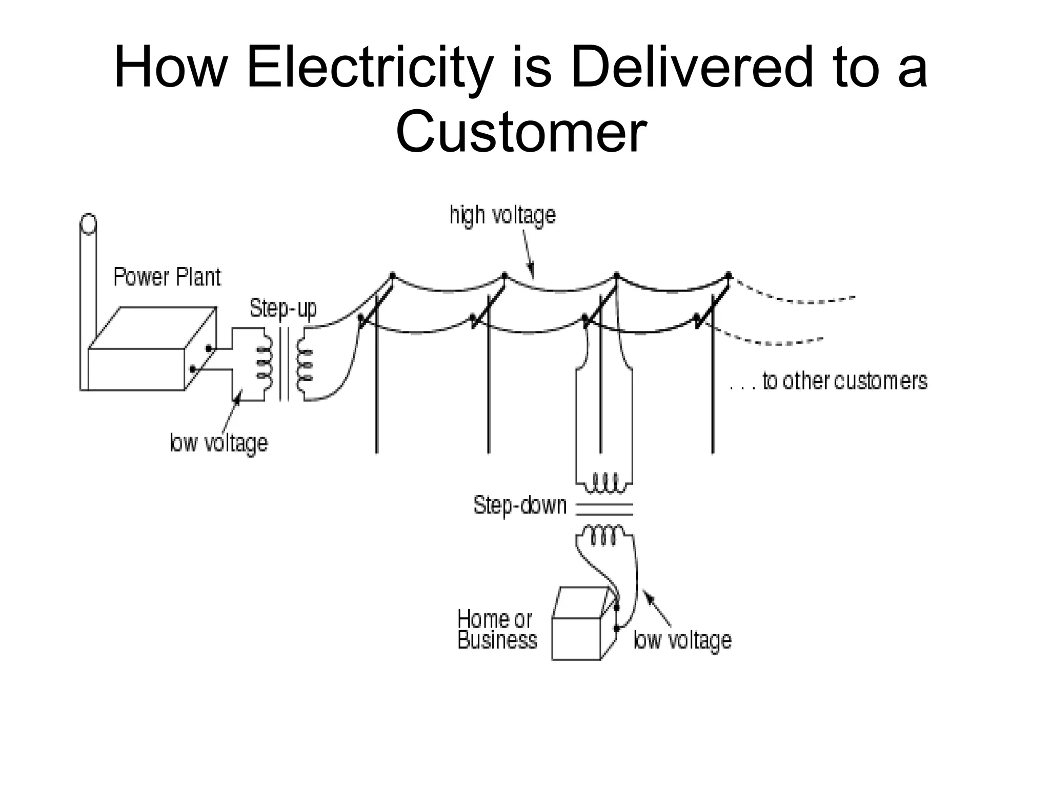
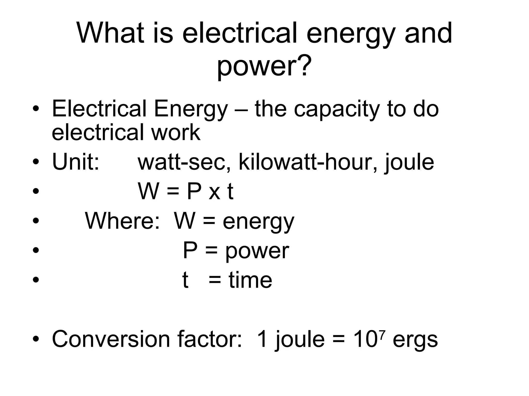
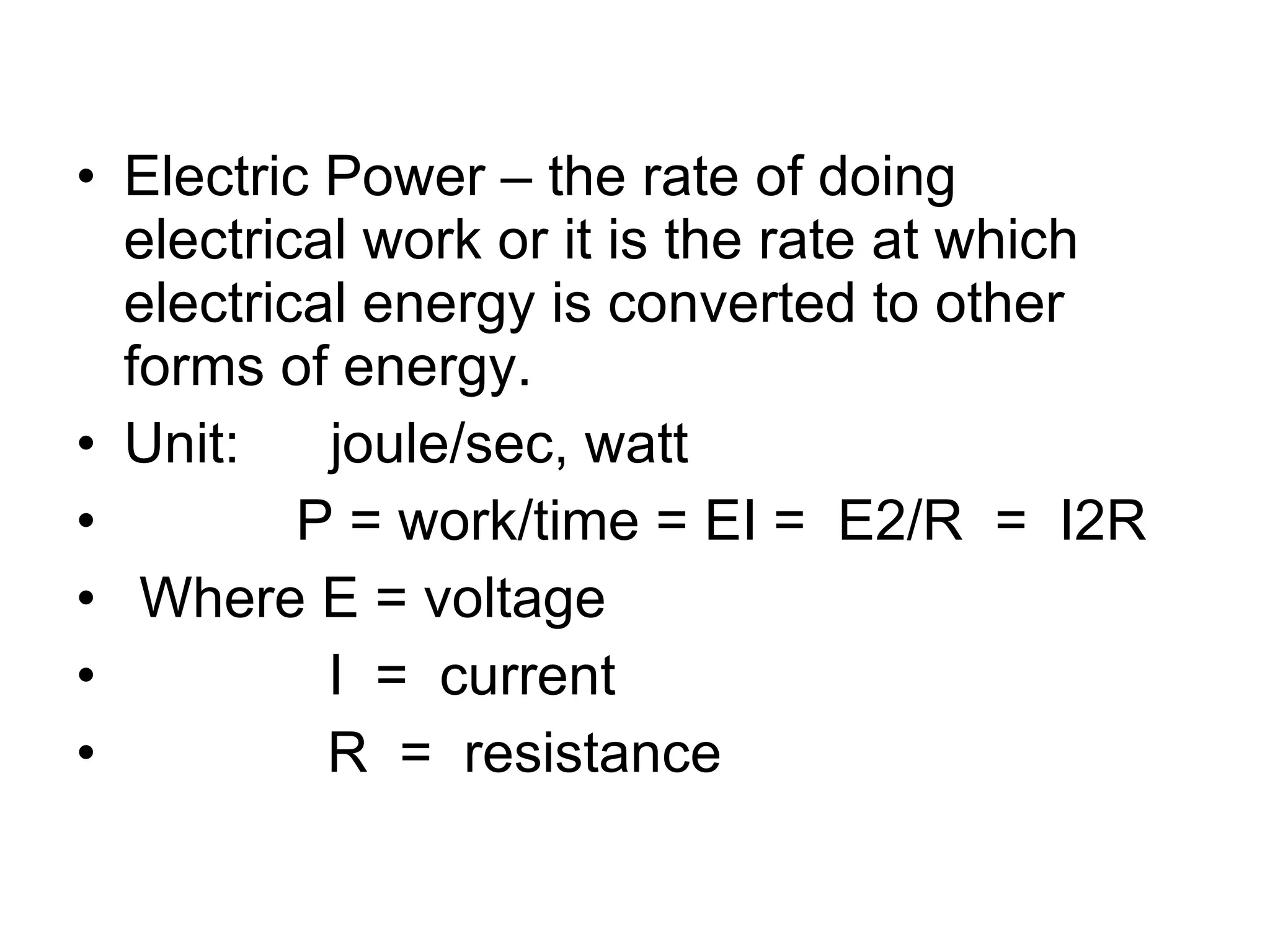
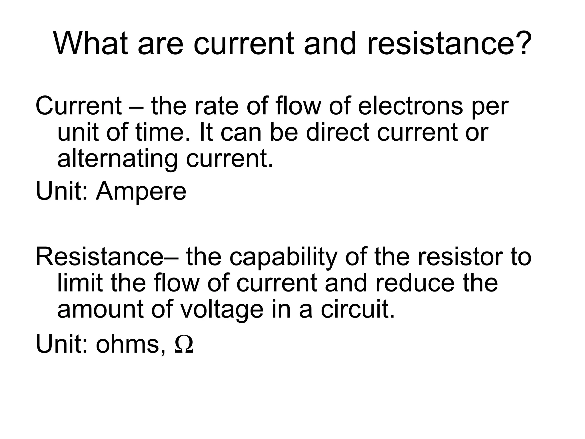
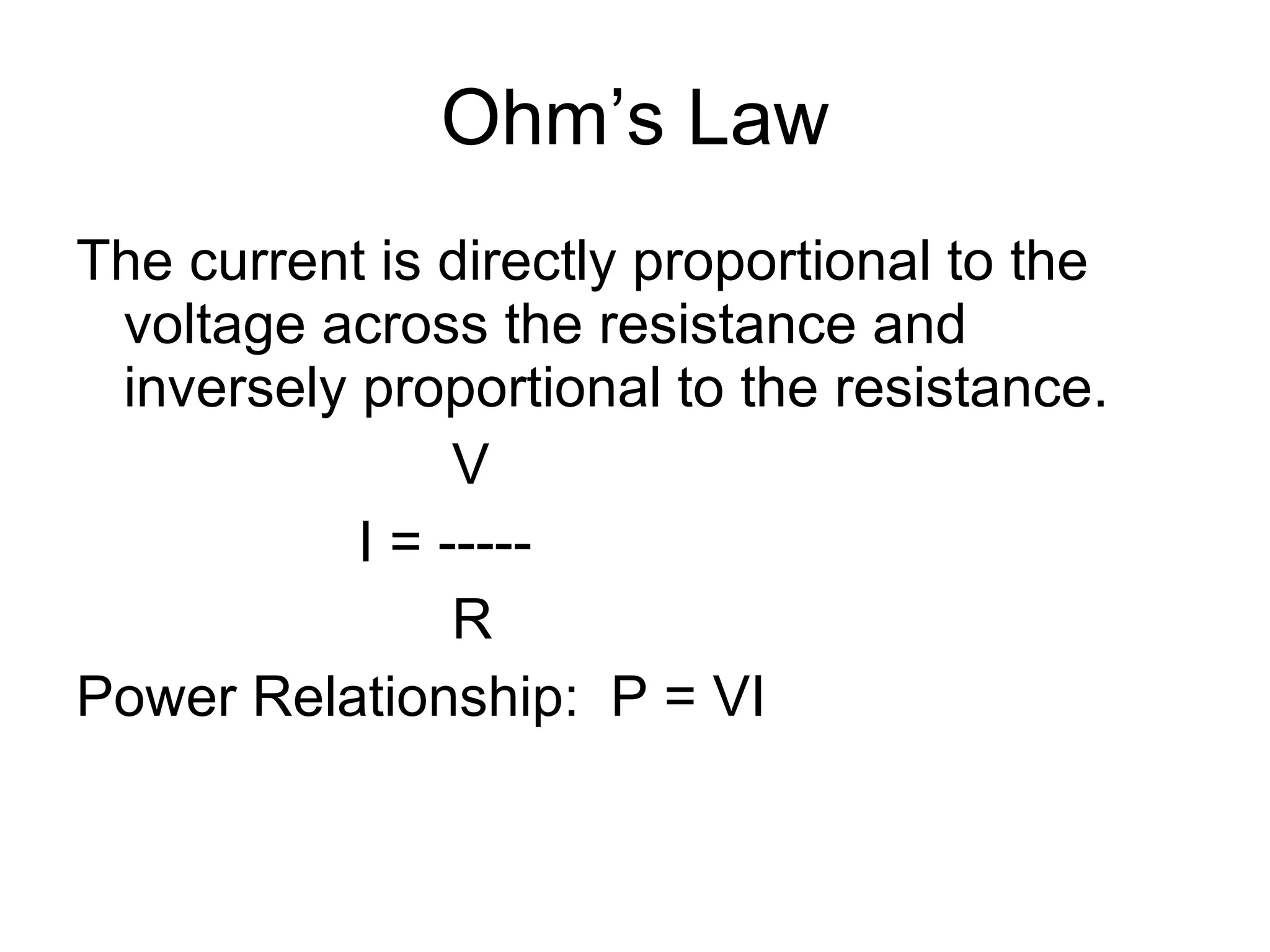
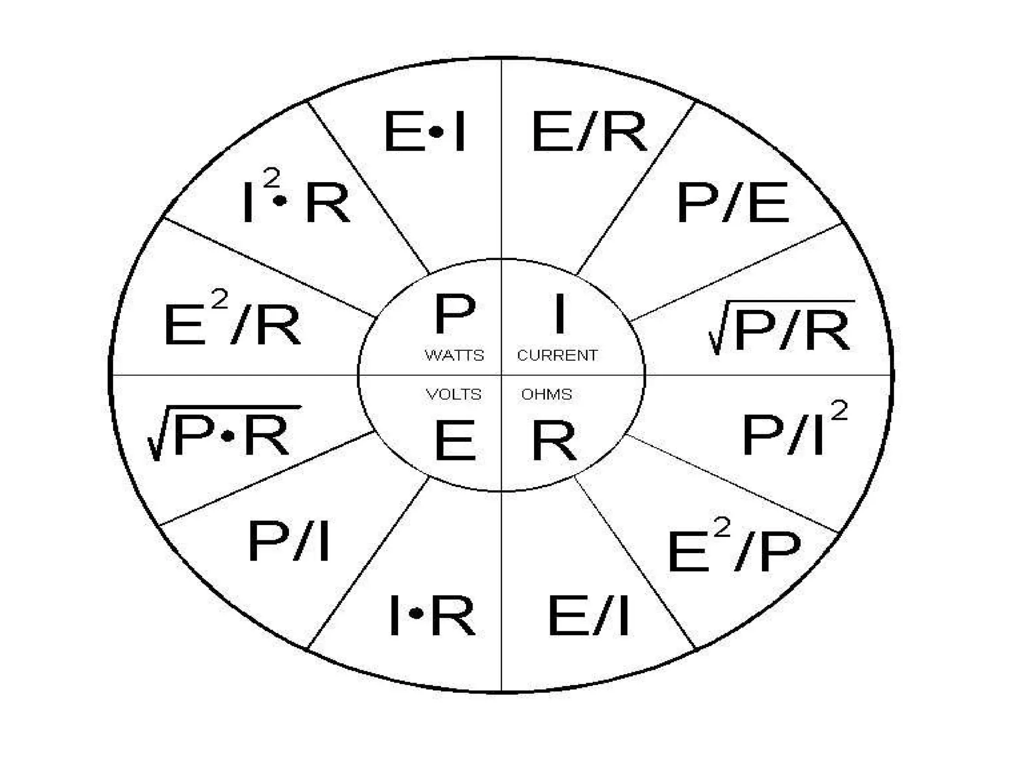
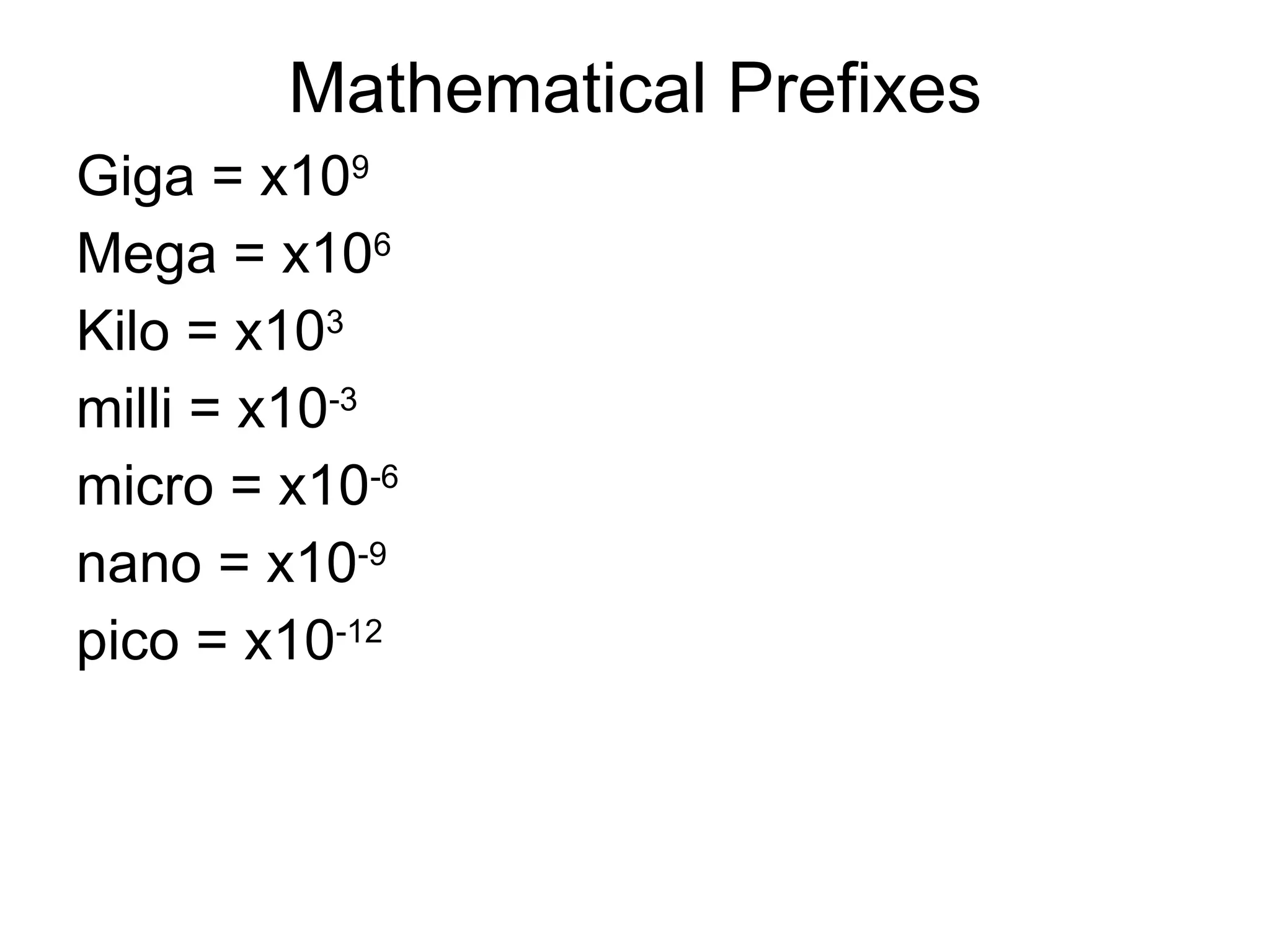
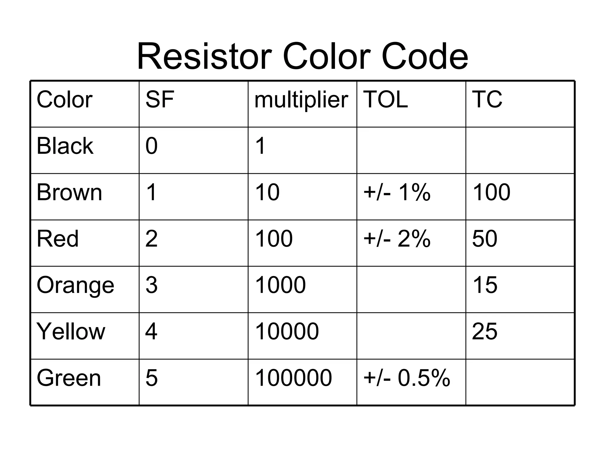
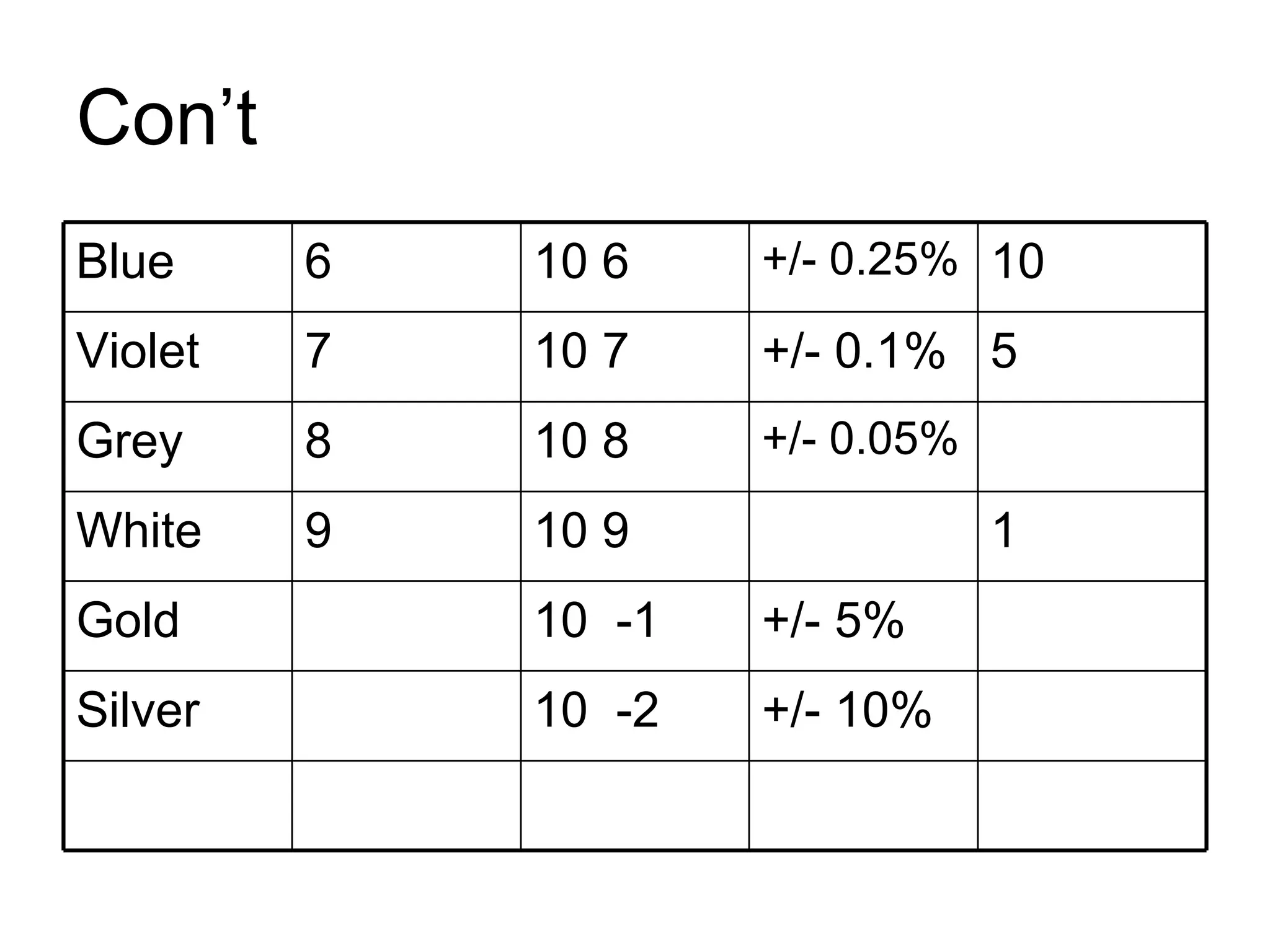
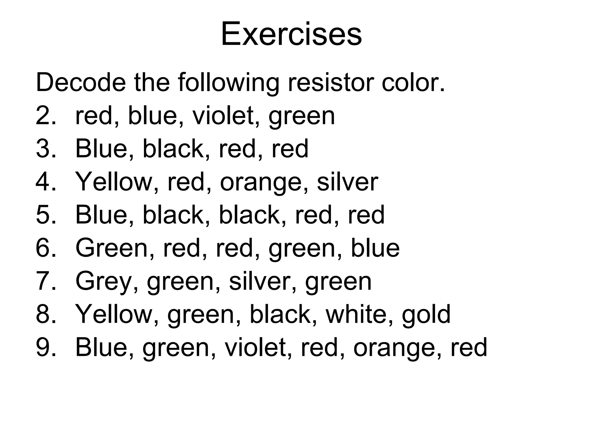
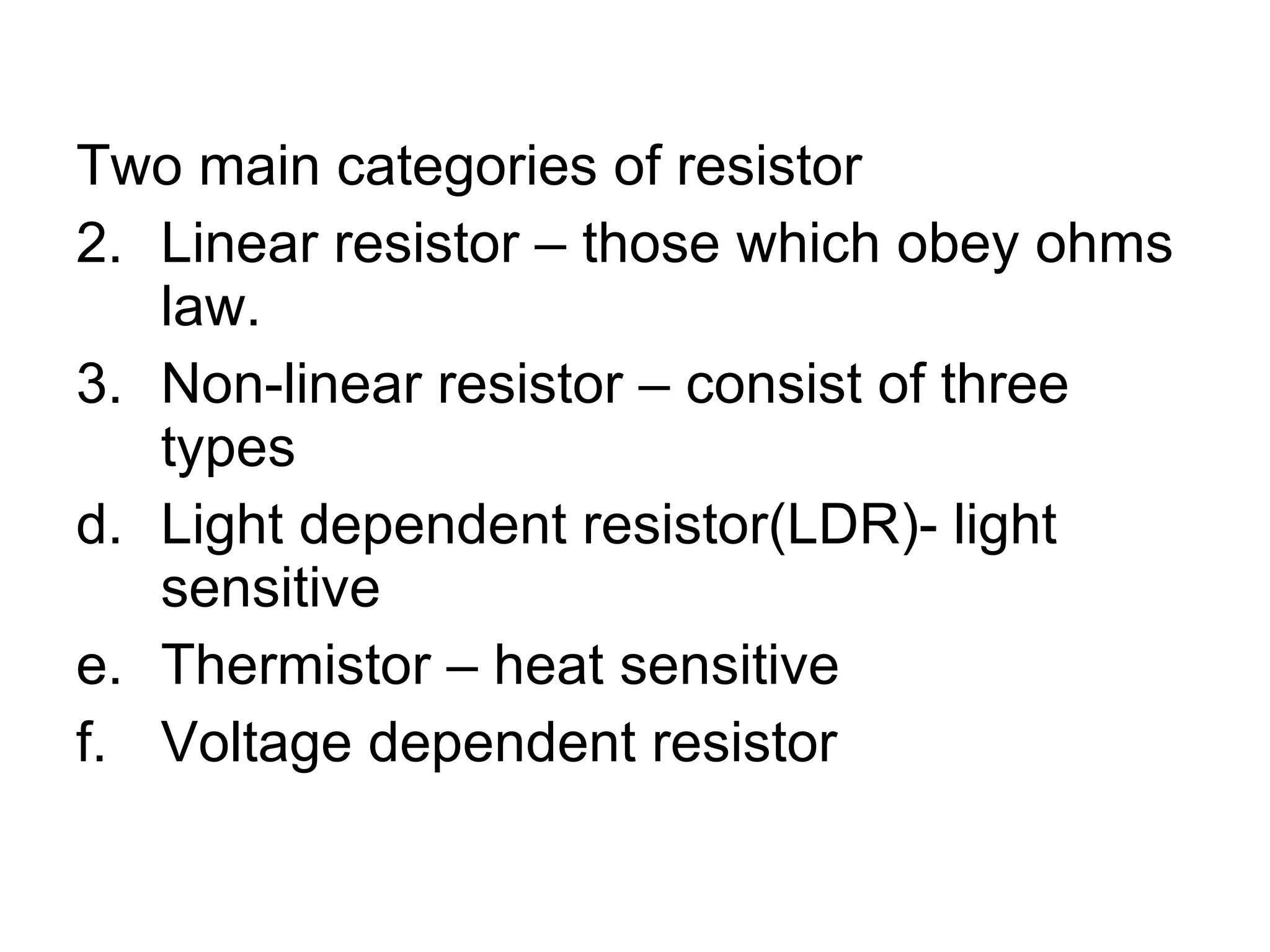
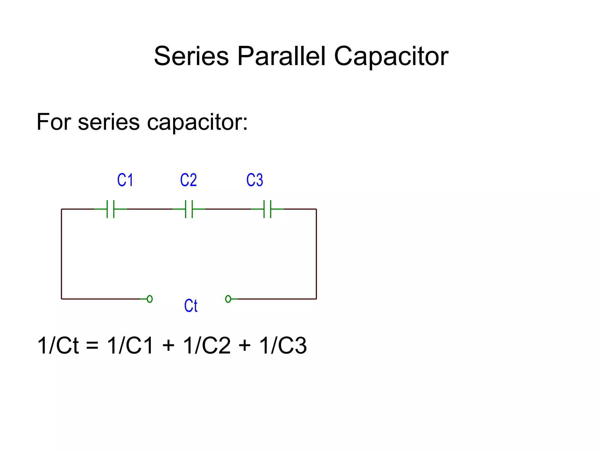
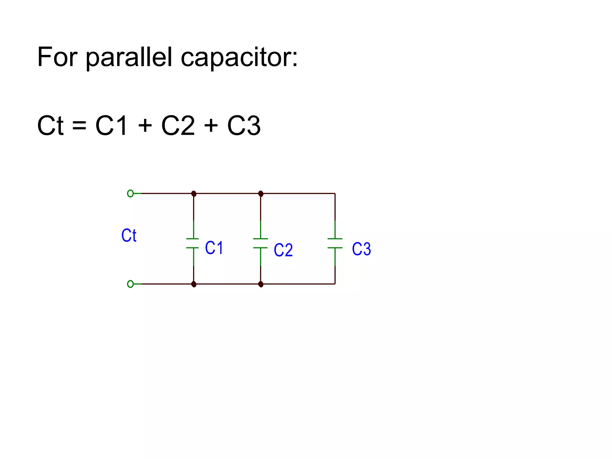
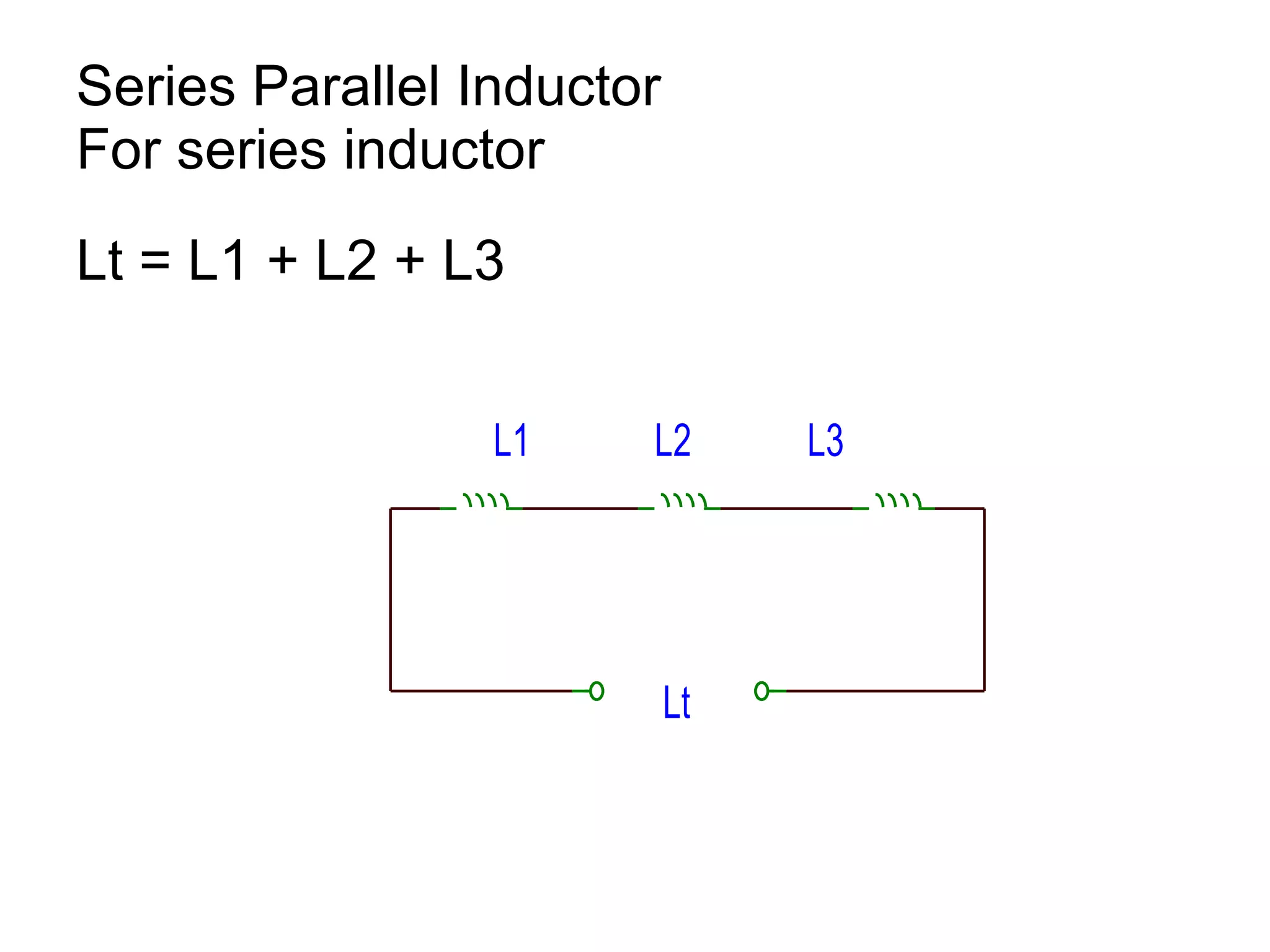
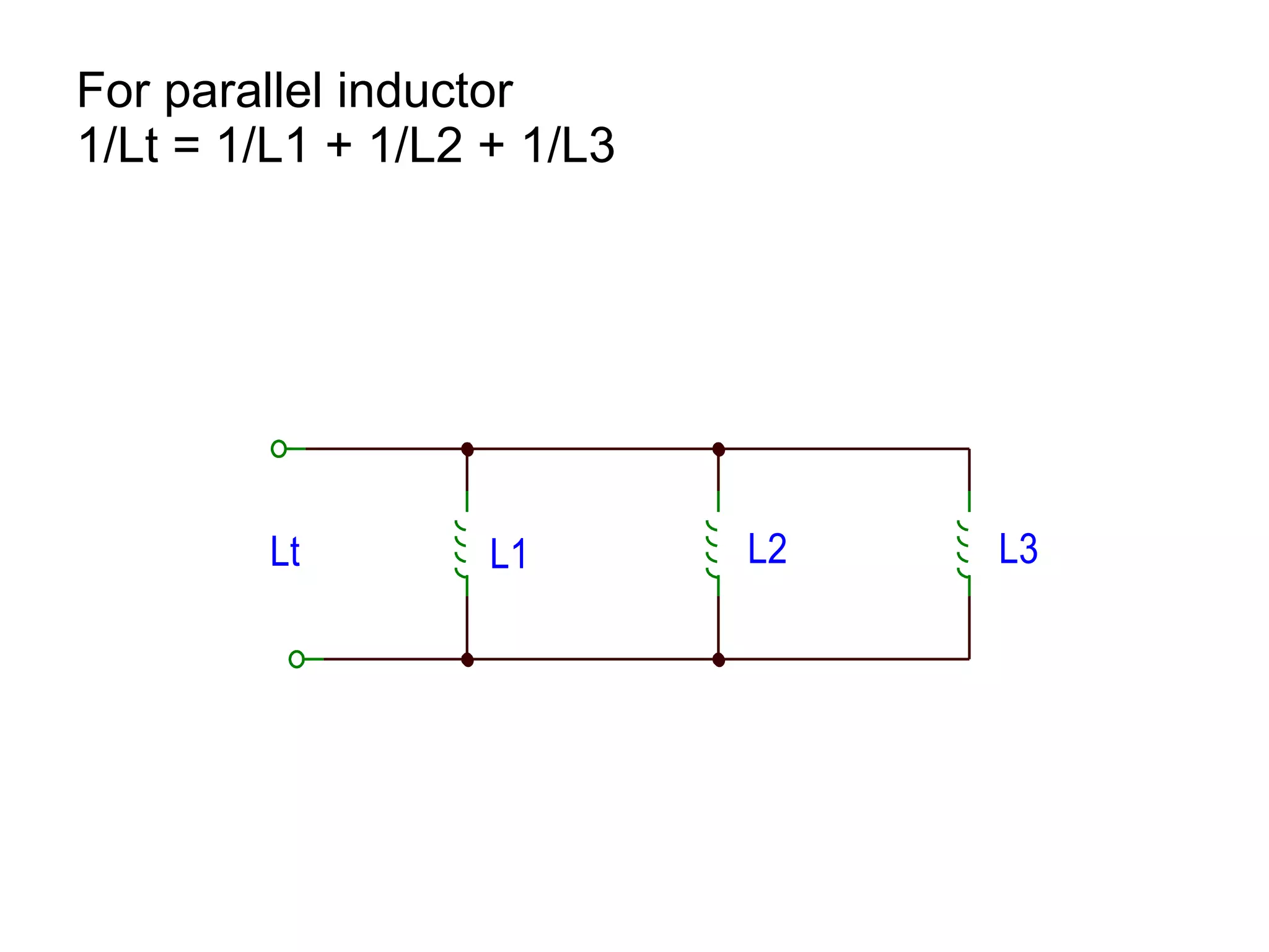
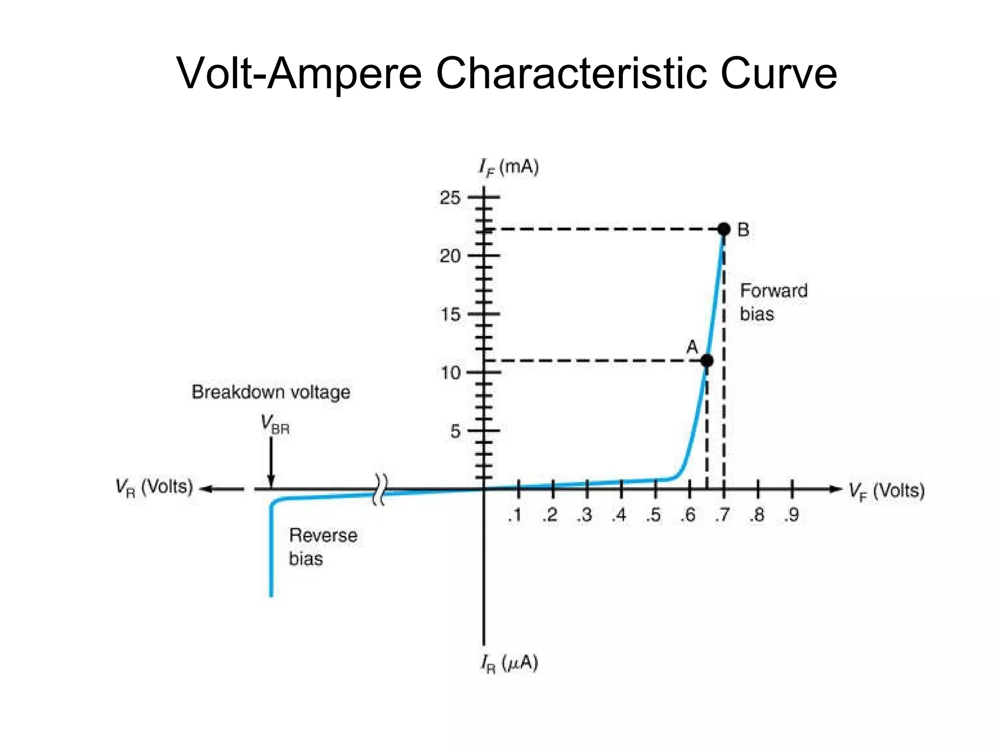
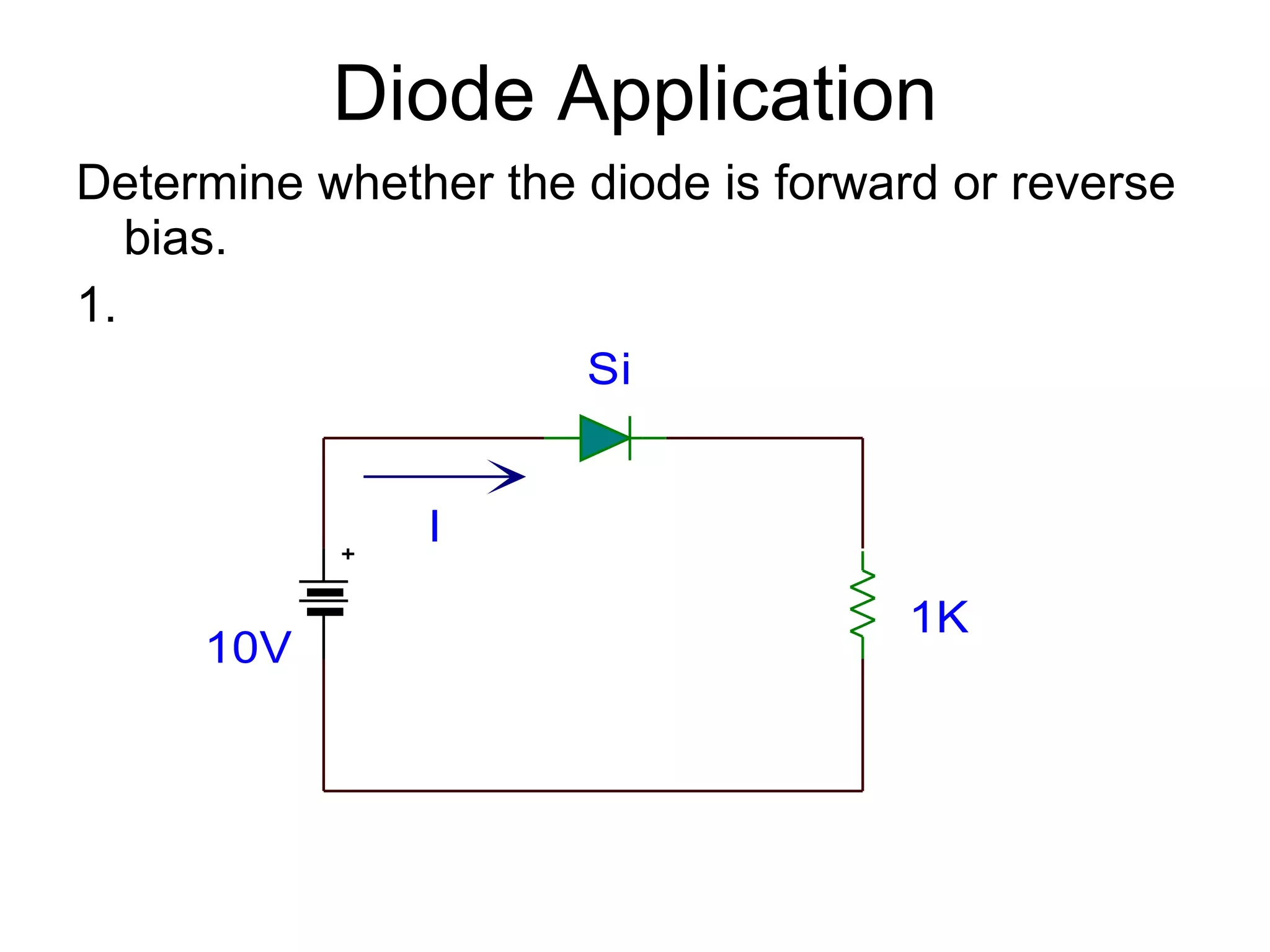
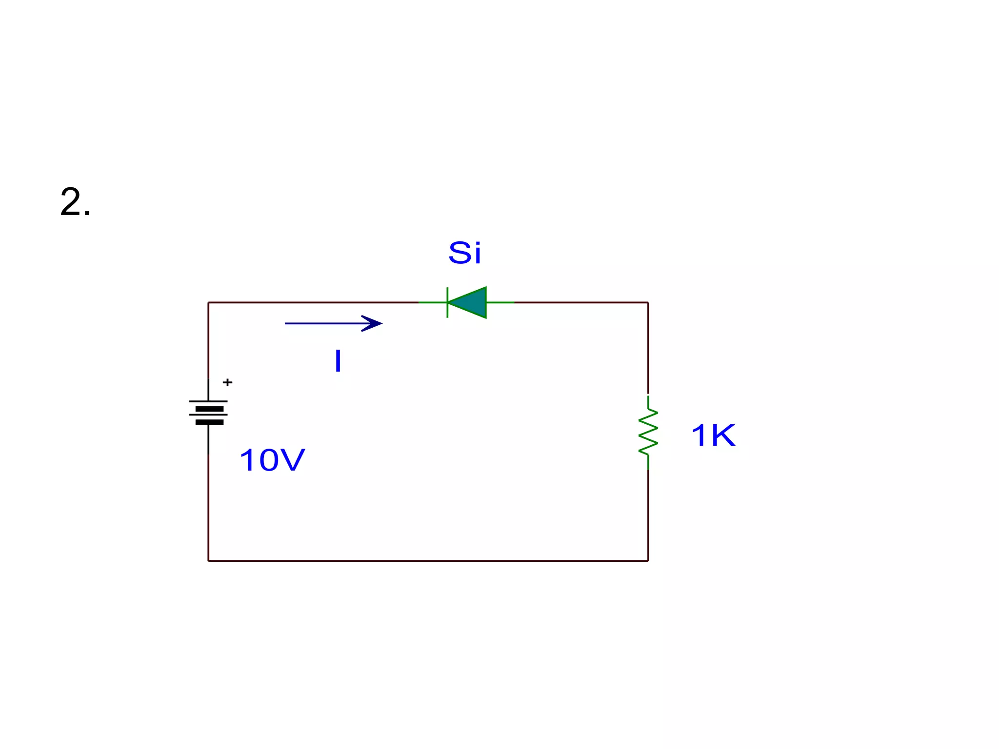
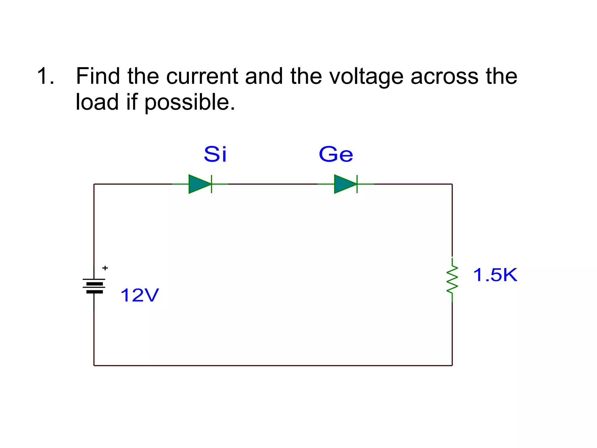
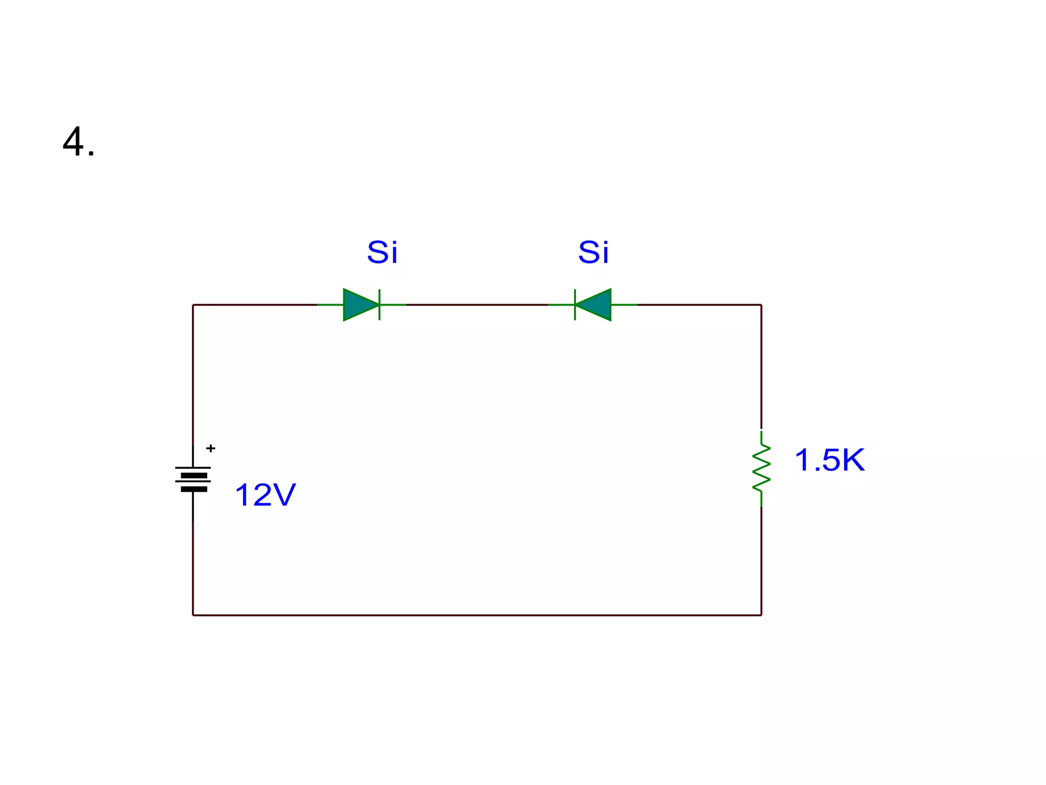
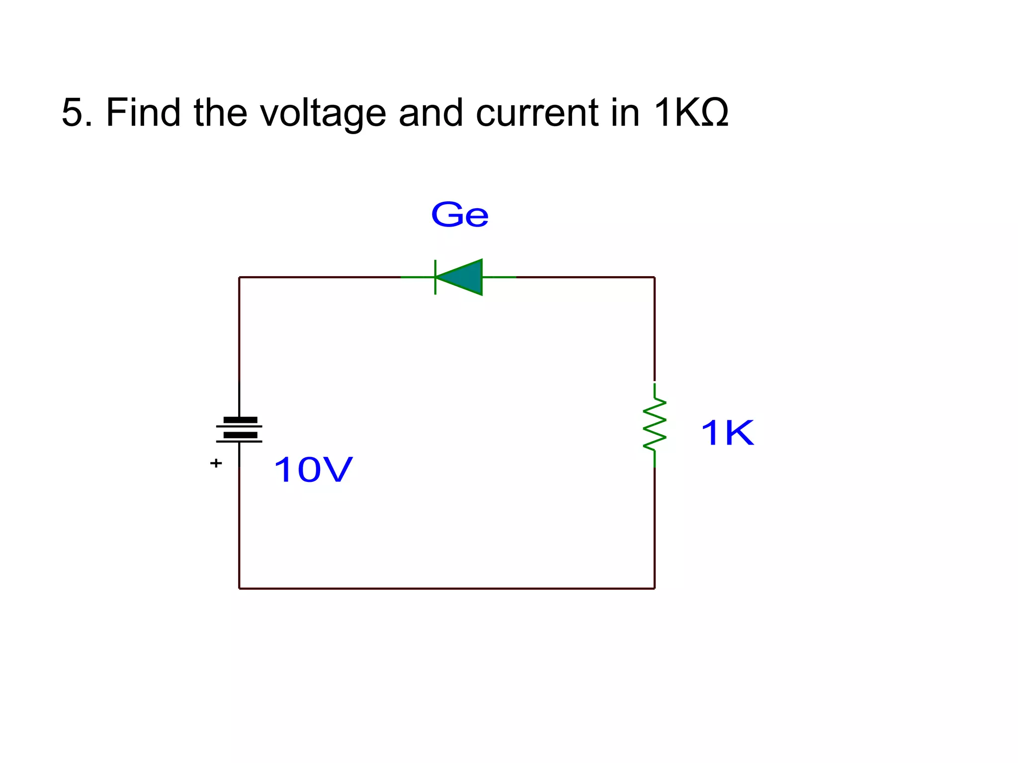
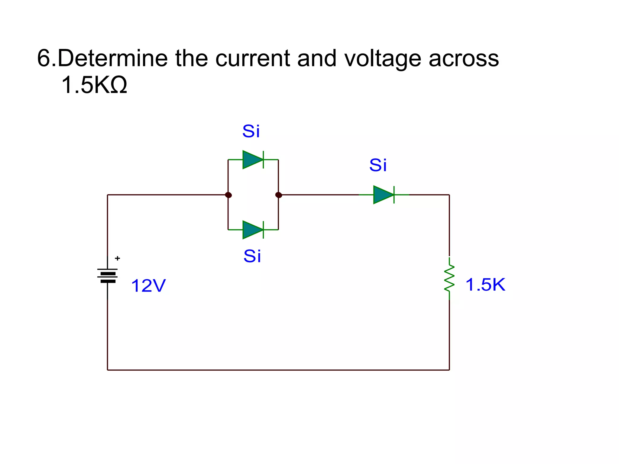
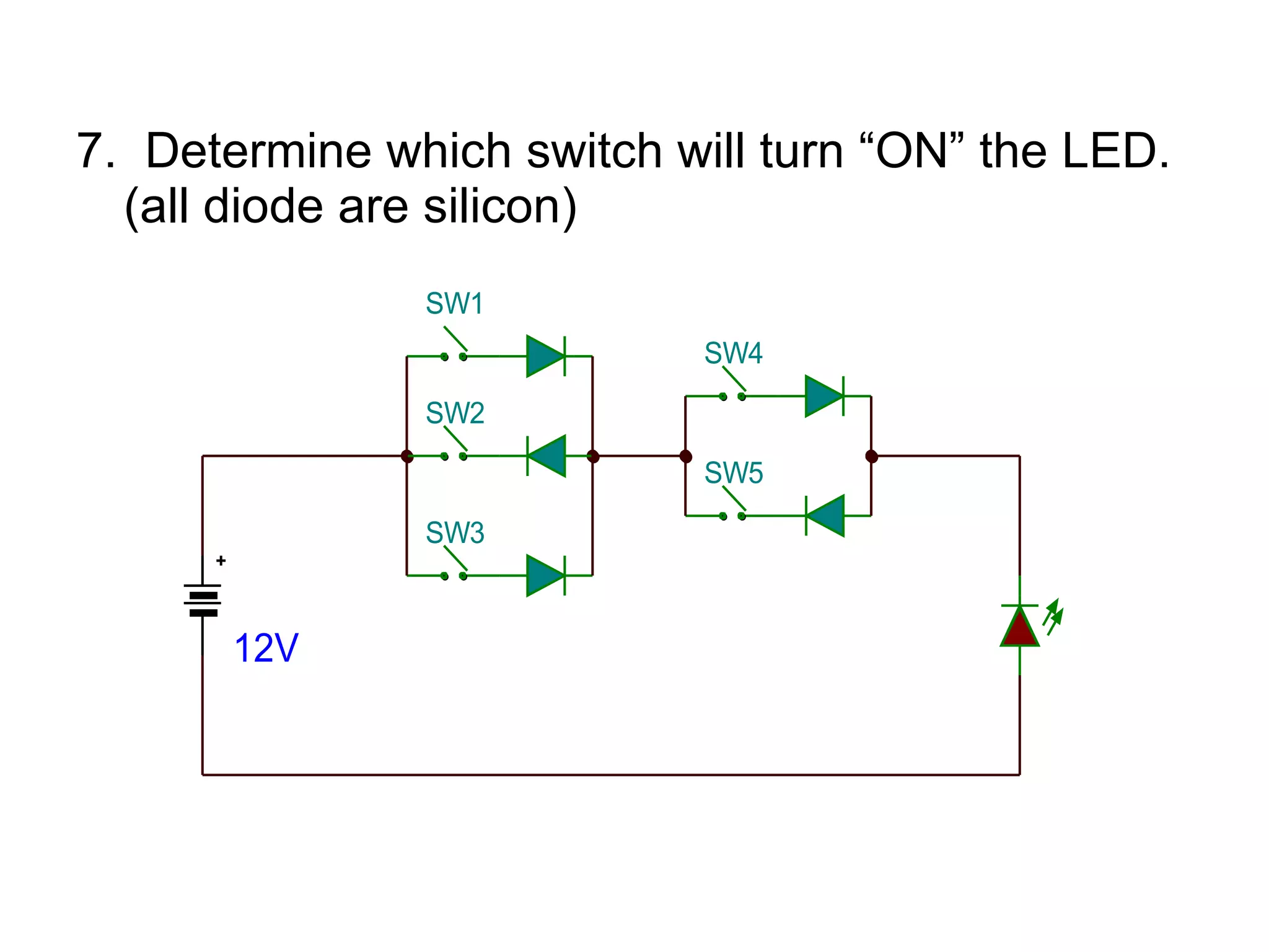
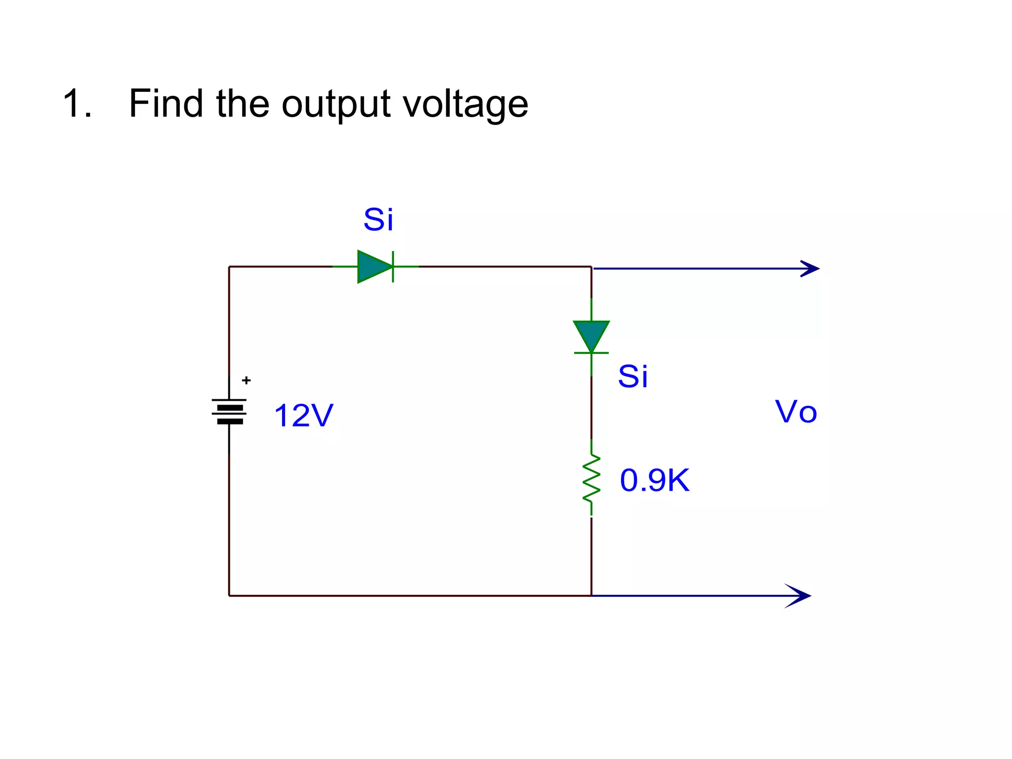
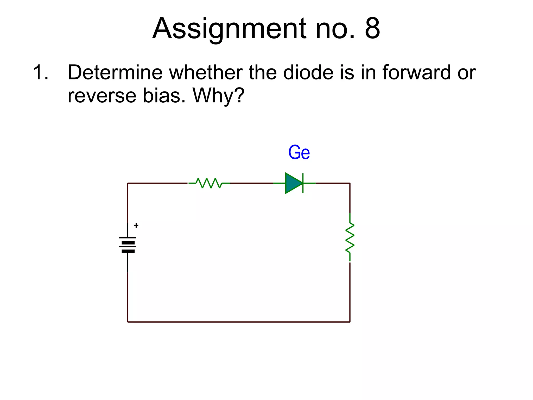
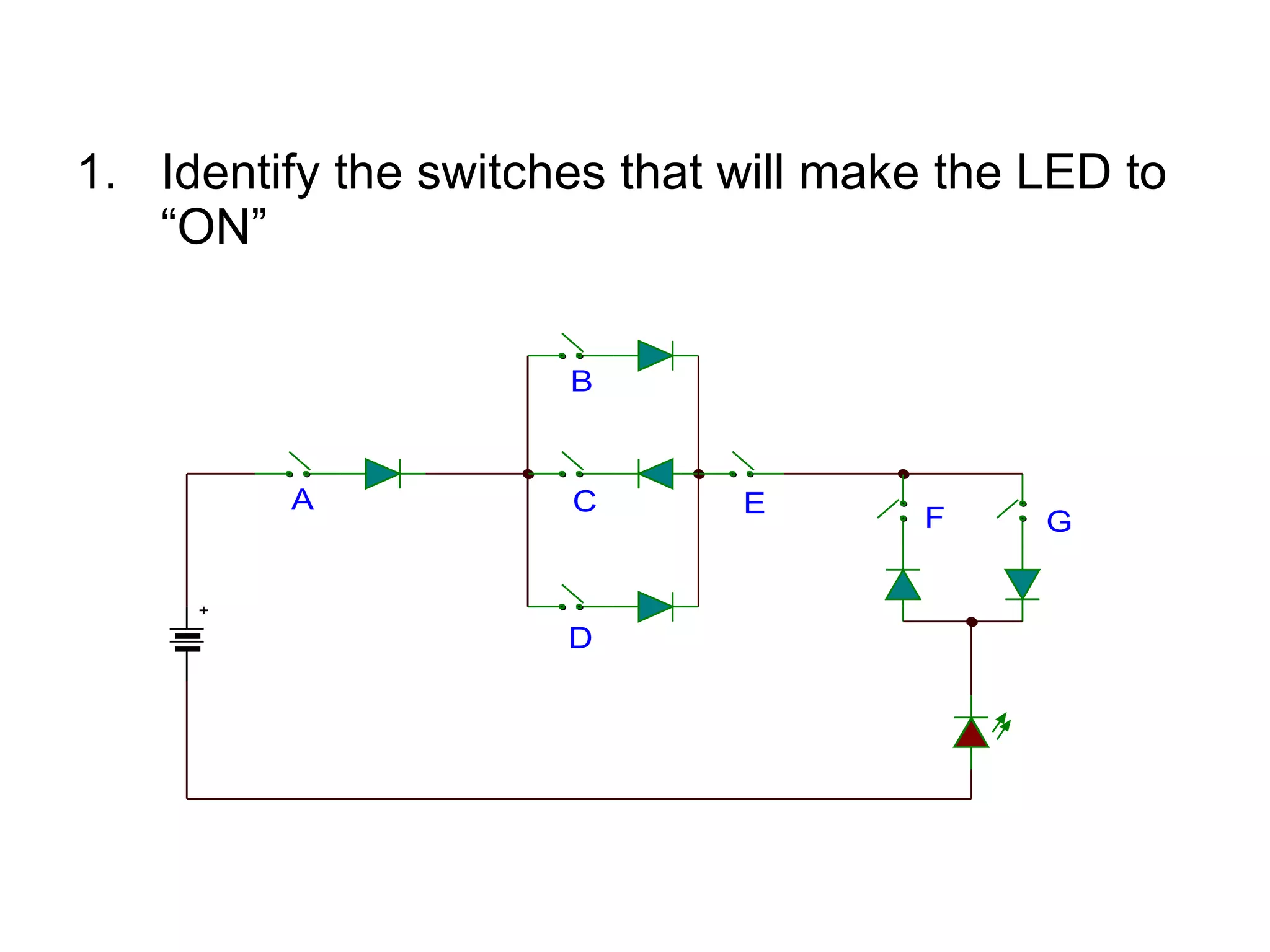
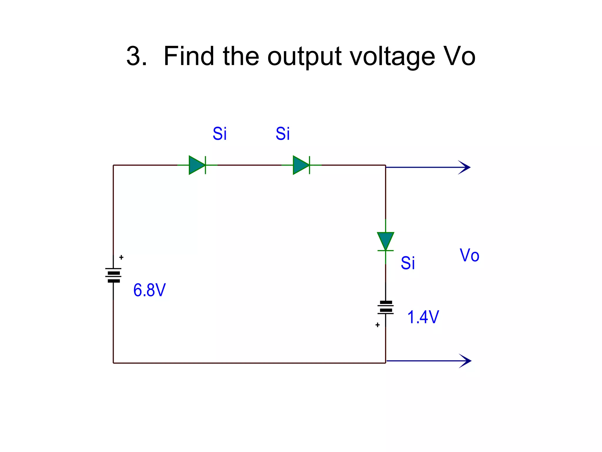
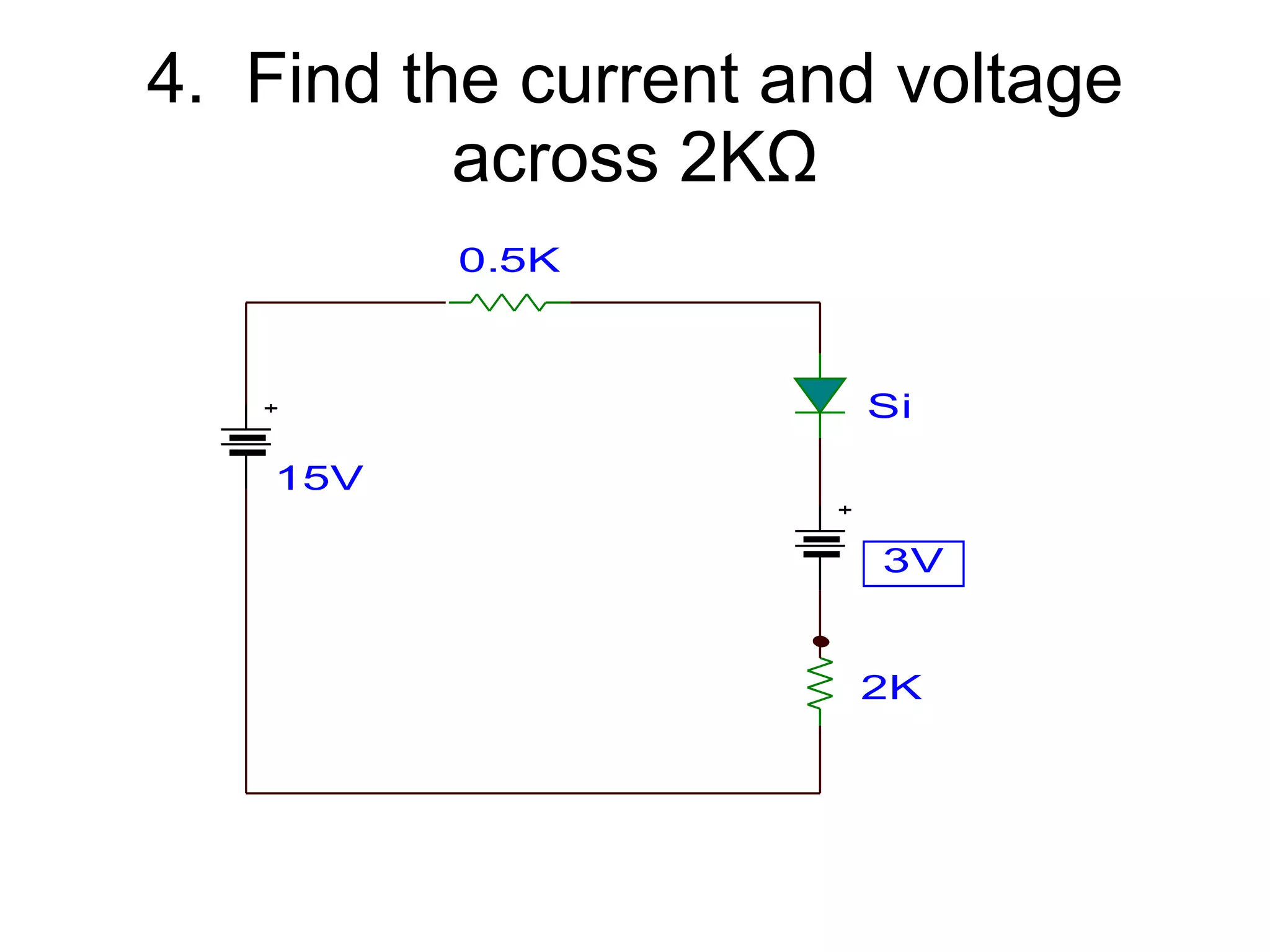
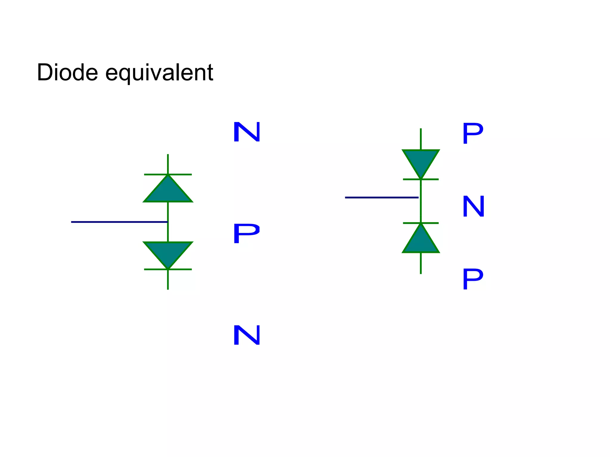
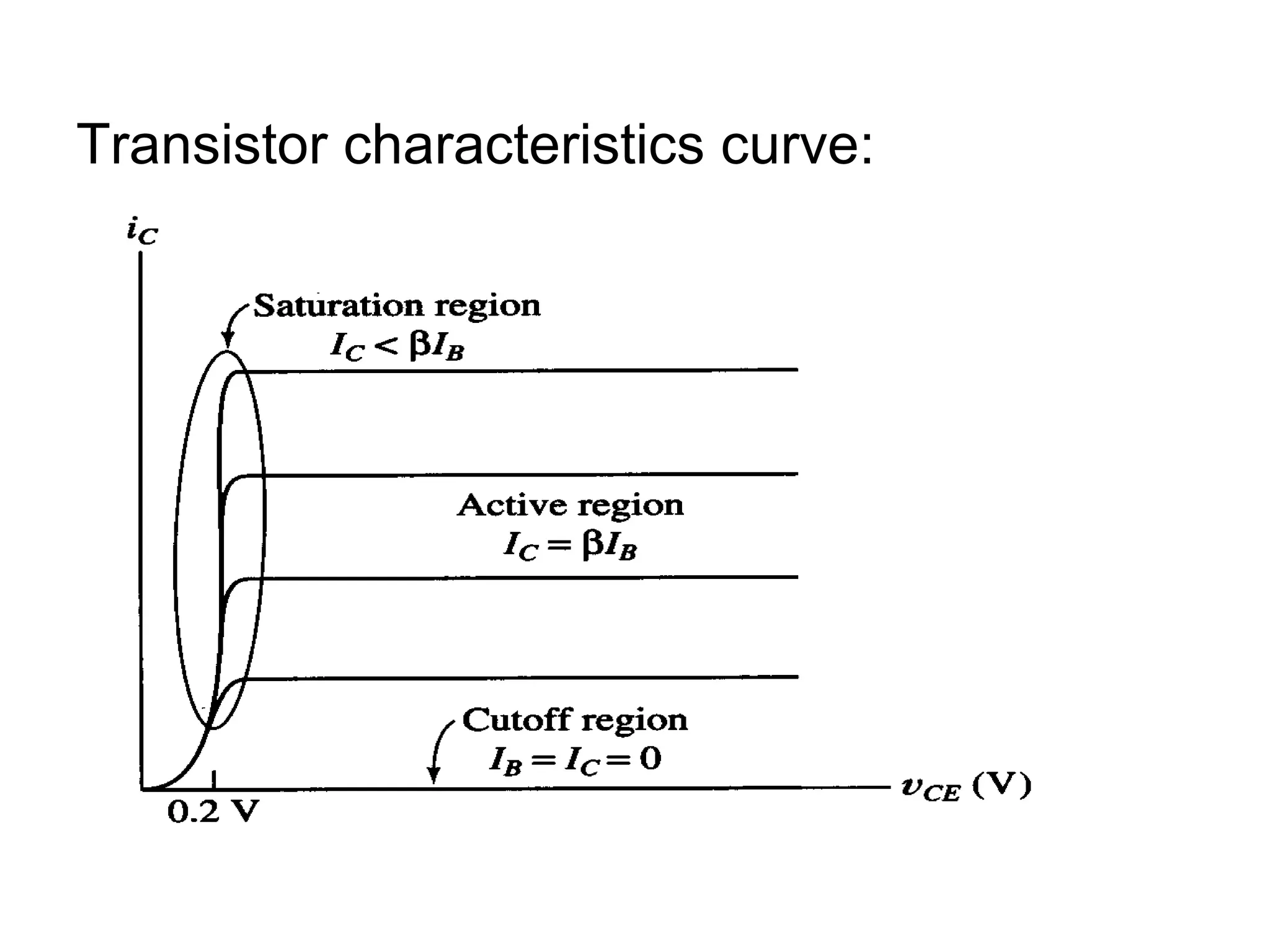
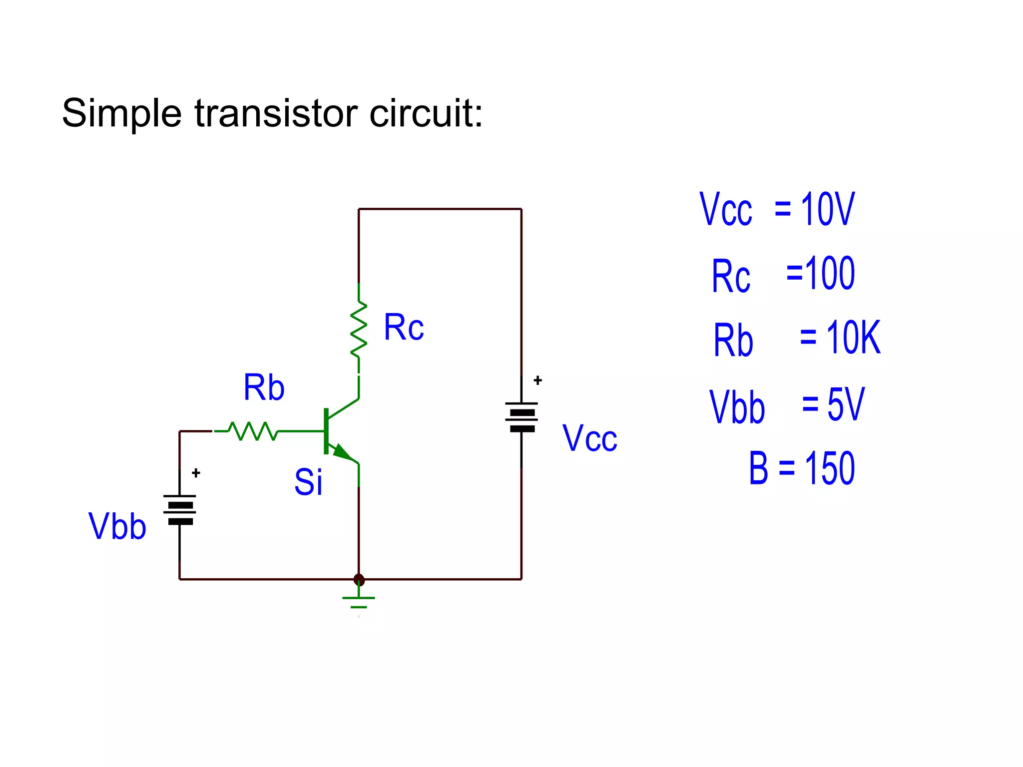
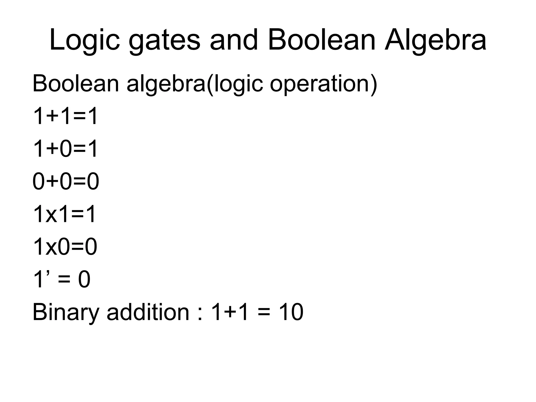
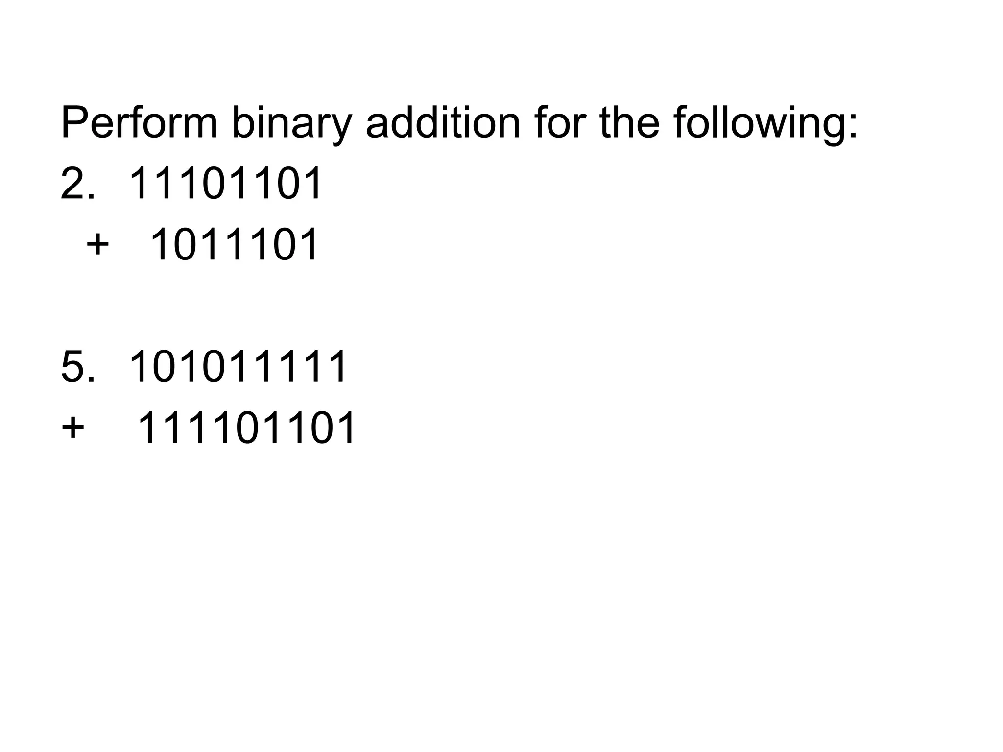

This document provides an outline for a course on electromagnetism, electricity, and digital electronics. The course covers topics such as the theory of electrons and electricity, resistors, Ohm's law, electric circuits, theory of magnetism, diodes, logic gates, and combinational and sequential circuits. It lists textbooks that will be used as references. The document also provides detailed explanations of concepts in atomic structure, electricity, circuits, electromagnetism, and electronics.


![Coded Agents – with UiPath SDK + LangGraph [Virtual Hands-on Workshop]](https://cdn.slidesharecdn.com/ss_thumbnails/codedagentsdeck-251215155422-5497c599-thumbnail.jpg?width=640&height=640&fit=bounds)


