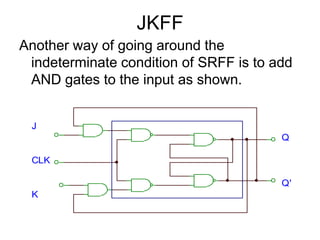
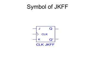
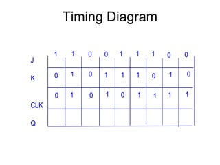
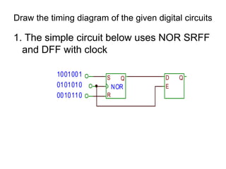
Downloaded 31 times


![Design a logic circuit that would generate the given function.f(a,b,c) = a’b + c(ab+b’)f(a,b,c) = a[b’c’ + ab]’ + ac’f(a,b,c) = a + bc + b(a’bc’)](https://image.slidesharecdn.com/electromagnetismanddigitalelectronics-101005053924-phpapp01/85/COMPLETE-FINAL-EMAG-PPT-156-320.jpg)
![Assignment No. 8Design the given function using logic gates and construct the truth table and timing diagram.X = abd’ + d(a + bc’)Y = bd’ + (a + b + c’)(a’ + b’ + cd)f(a,b,c,d) = (ab + cd)(a’b + ab’)X = abc’ + bcd’ + cd[ab’ + a’b]’Y = (abcd’)’(ab + bc + cd’)](https://image.slidesharecdn.com/electromagnetismanddigitalelectronics-101005053924-phpapp01/85/COMPLETE-FINAL-EMAG-PPT-157-320.jpg)


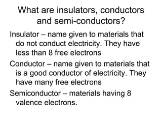
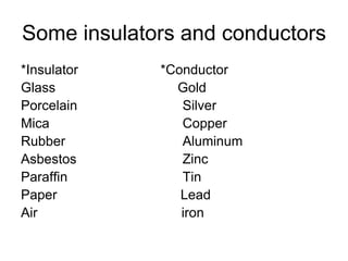
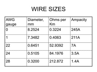
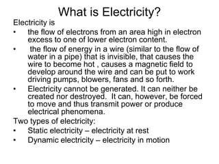
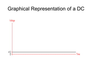
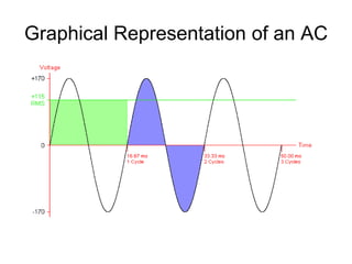
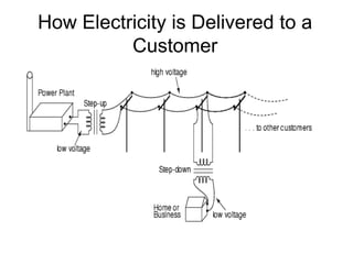
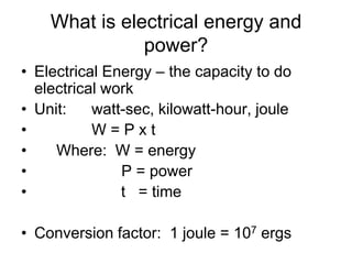
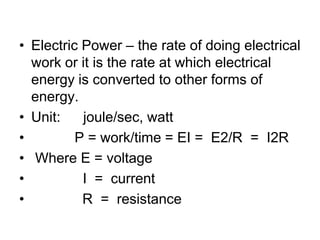
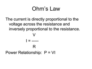
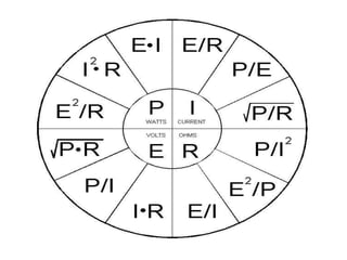
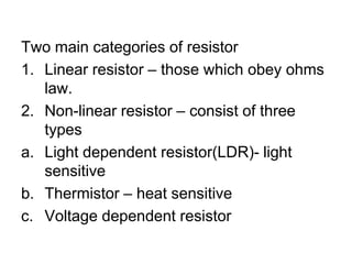
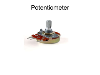
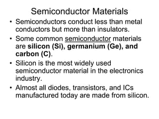
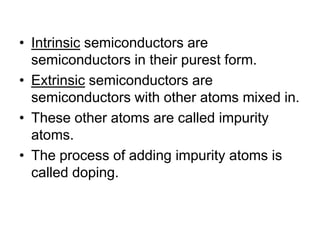
This document provides an outline for a course on electromagnetism, electricity, and digital electronics. The course covers topics such as the theory of electrons and electricity, resistors, Ohm's law, circuits, magnetism, diodes, logic gates, combinational and sequential circuits. References for the course include textbooks on digital design, electronic devices, engineering circuit analysis, and introductions to electric circuits and digital circuits. The document also provides details on some of the topics, including the theory of electrons, insulators/conductors/semiconductors, direct and alternating current, voltage, current, resistance, and Ohm's law.


