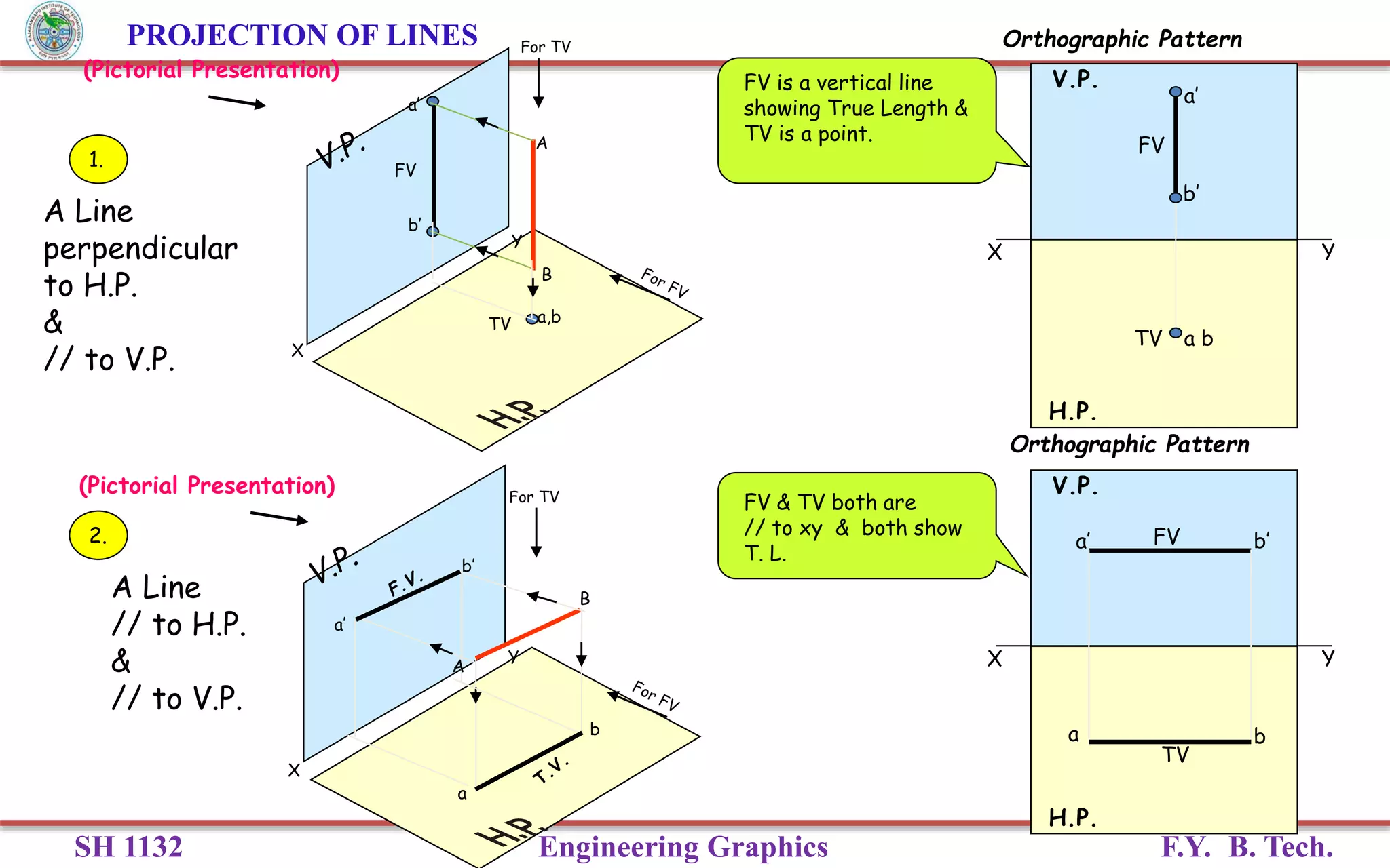
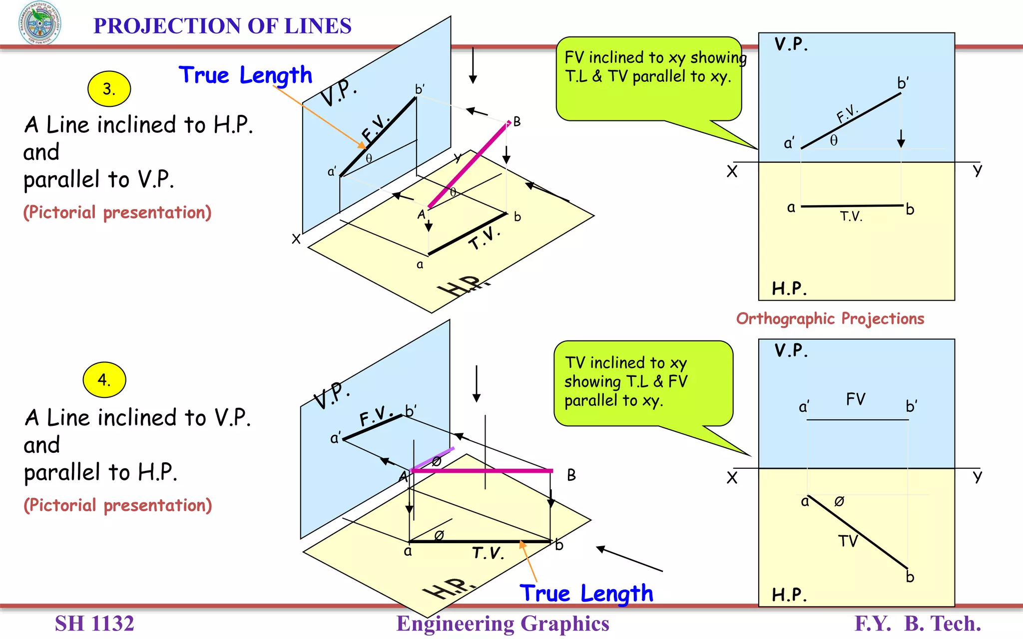
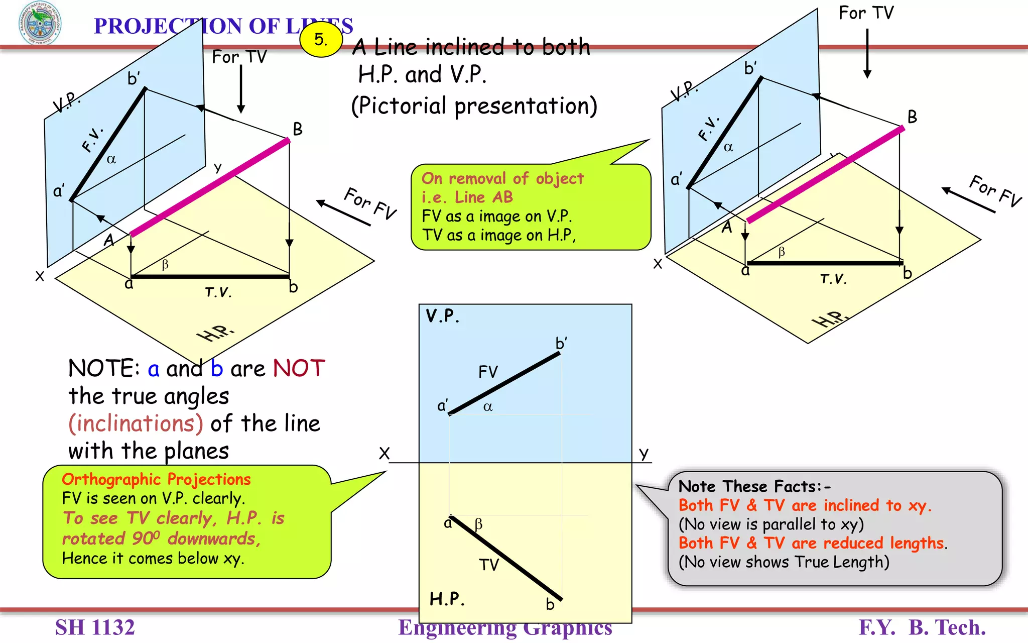
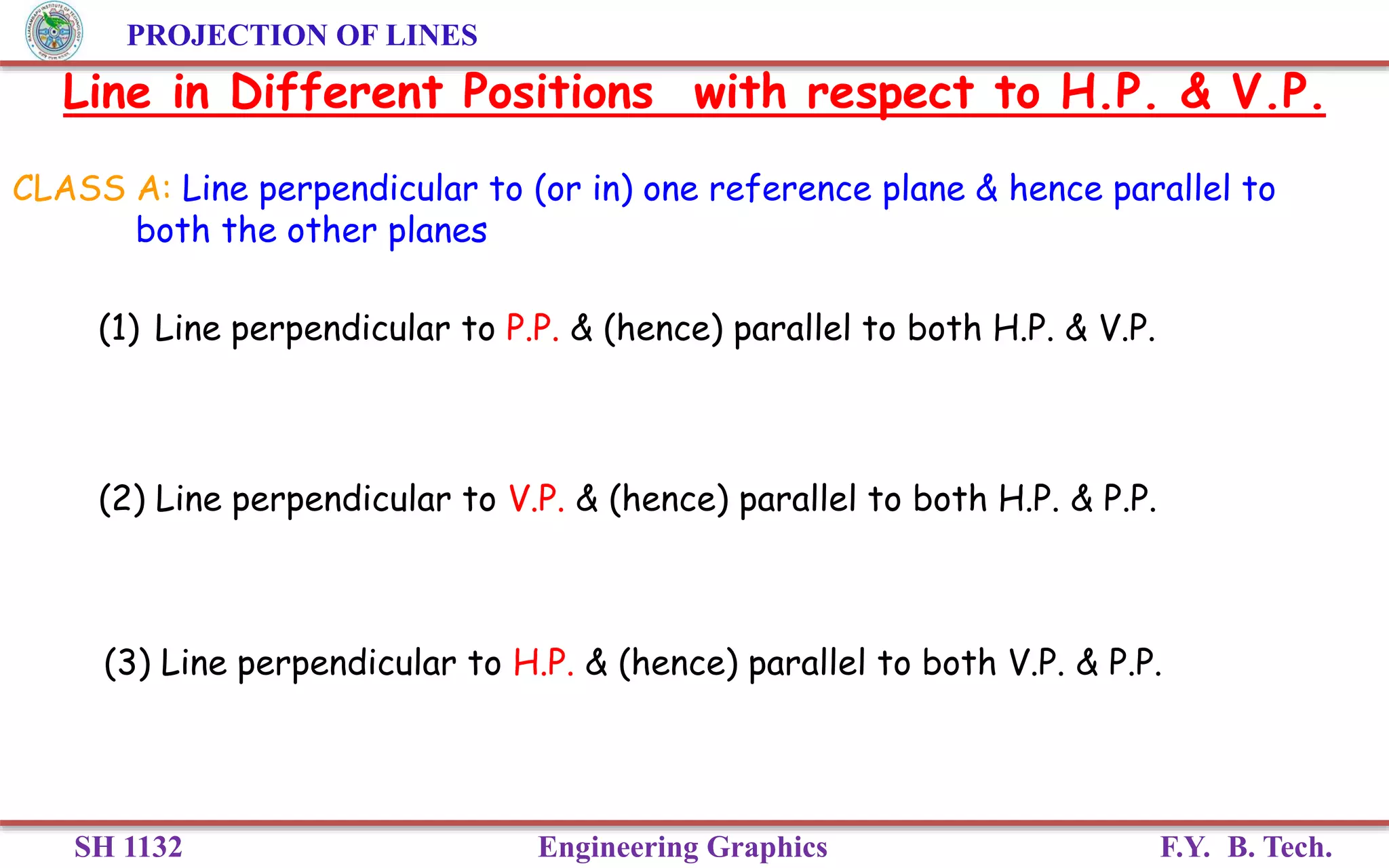
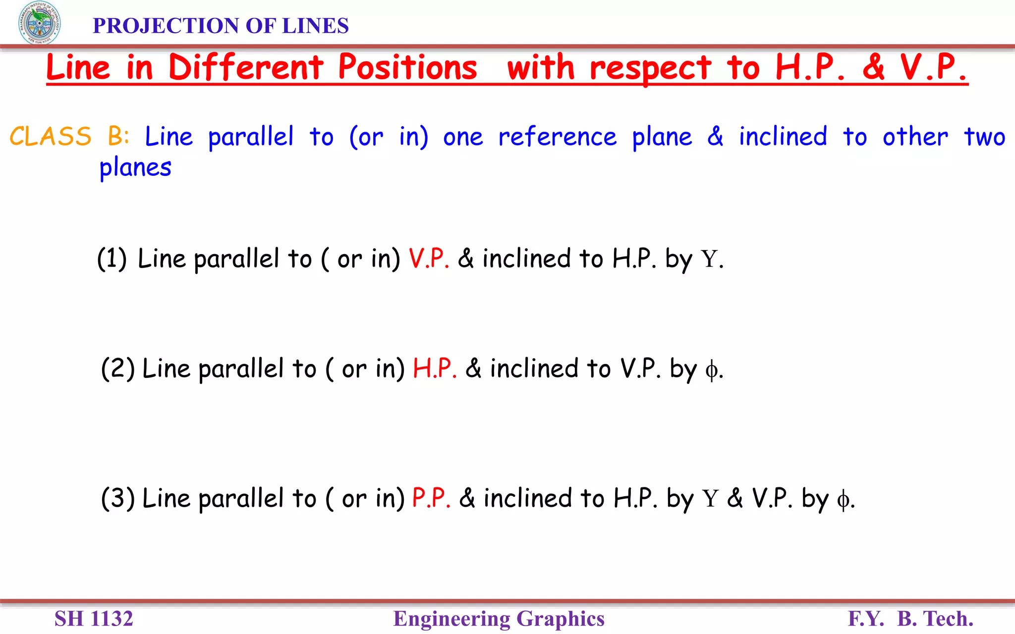
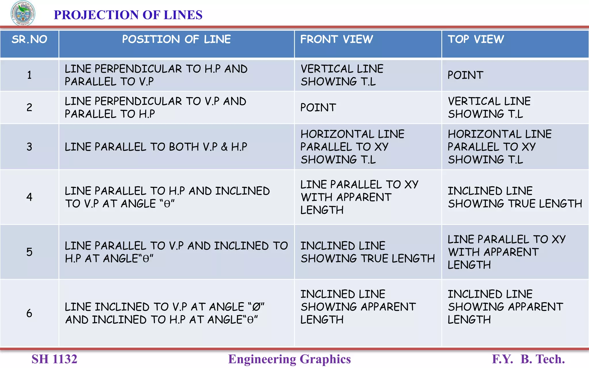
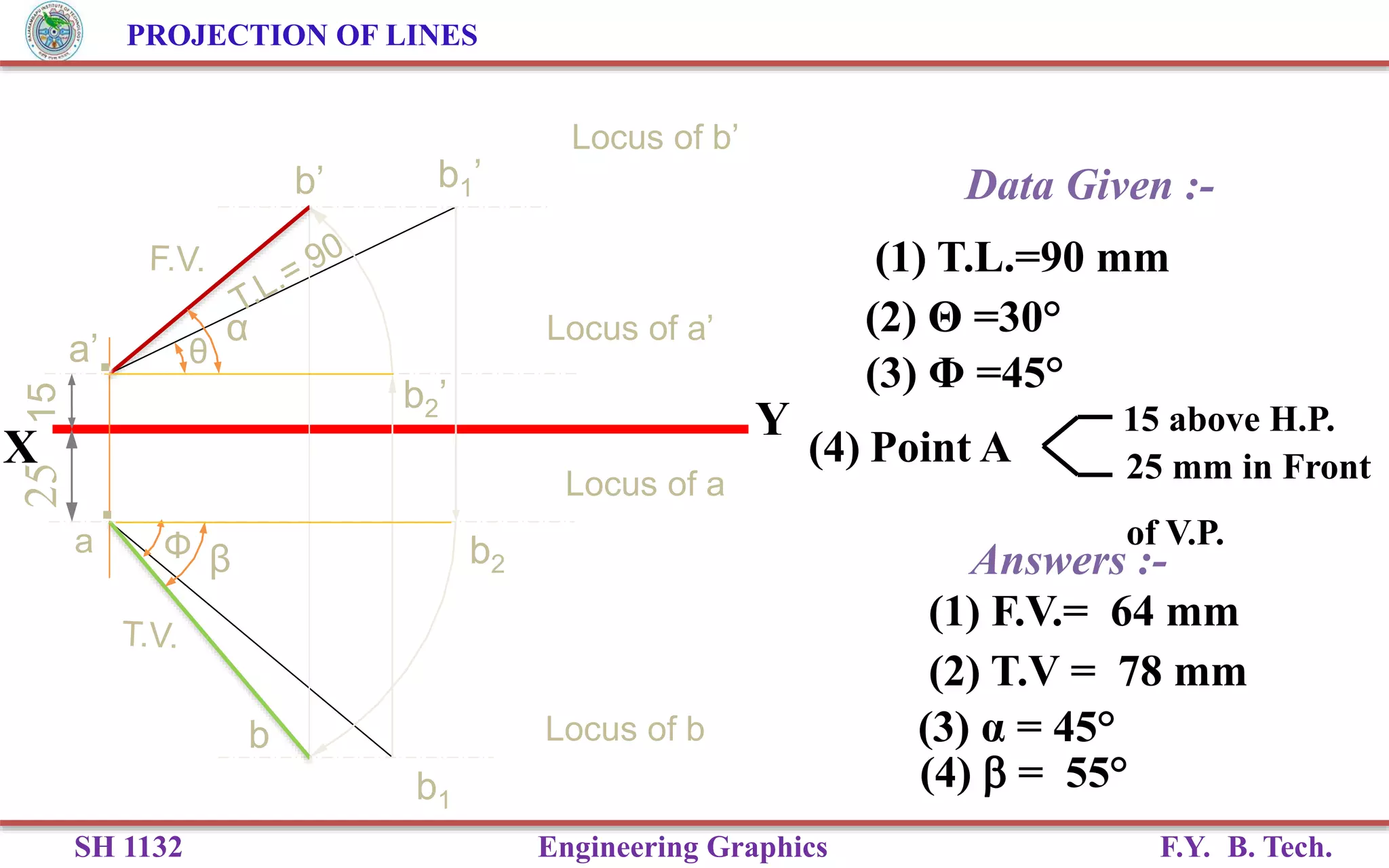
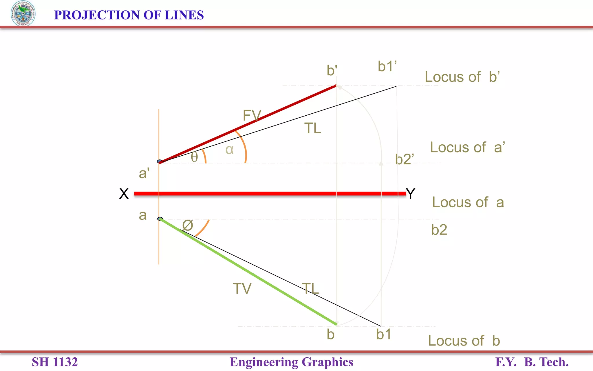
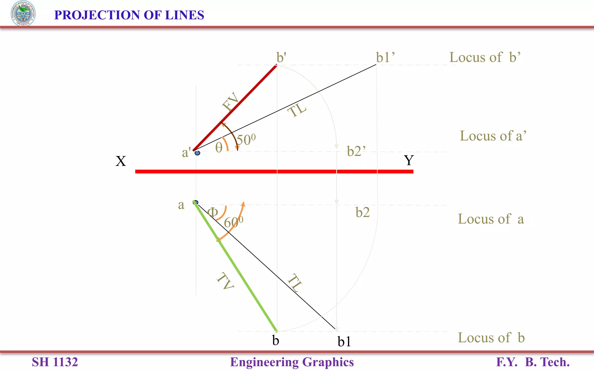
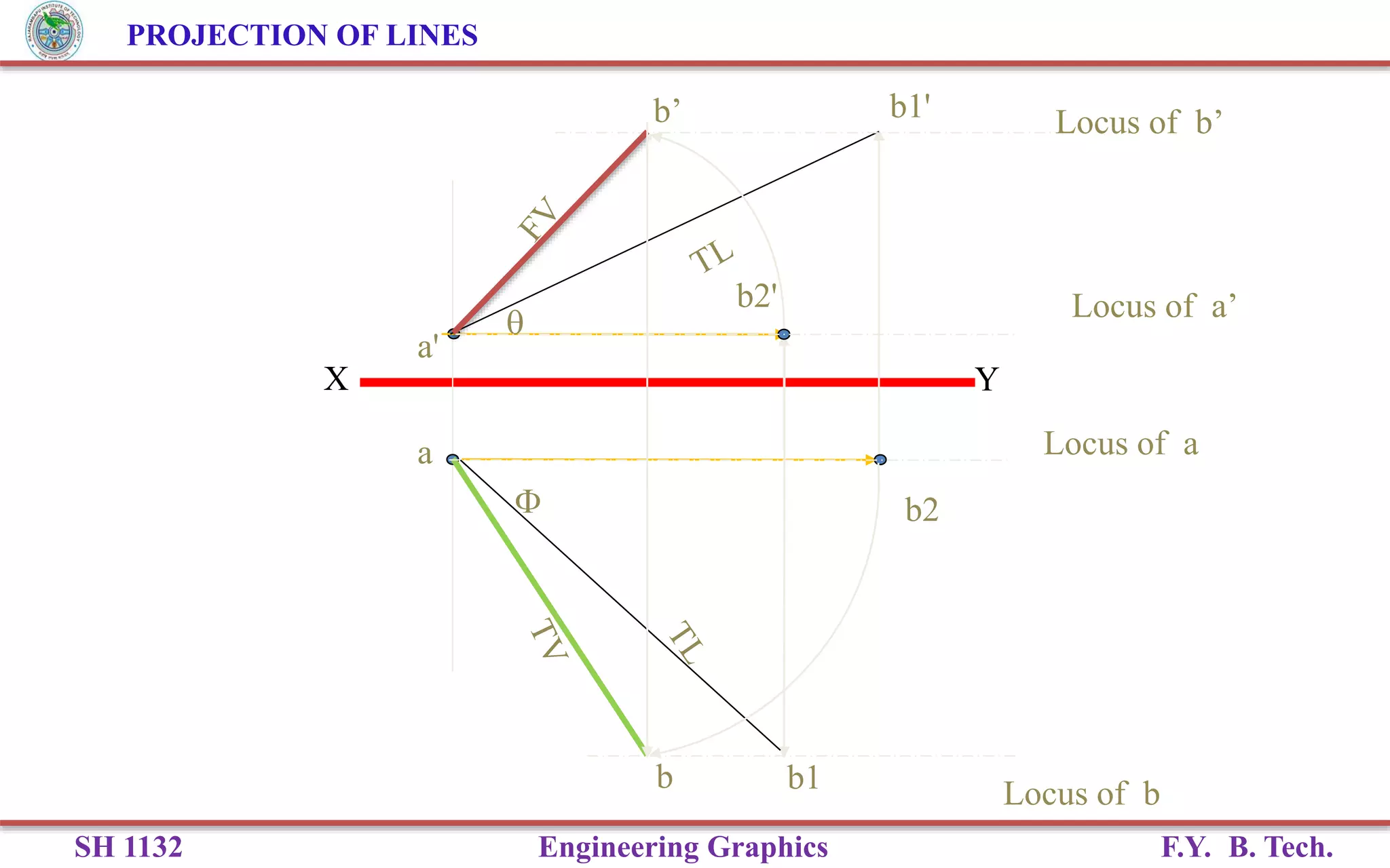
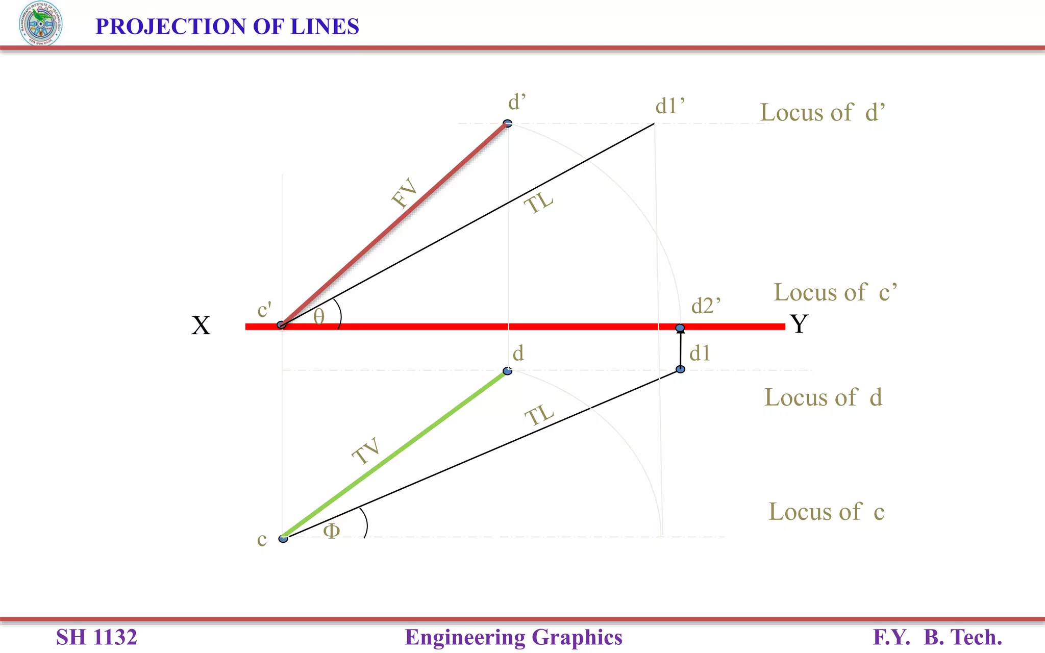
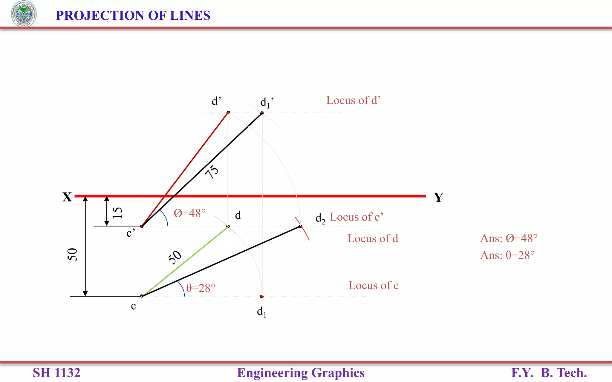
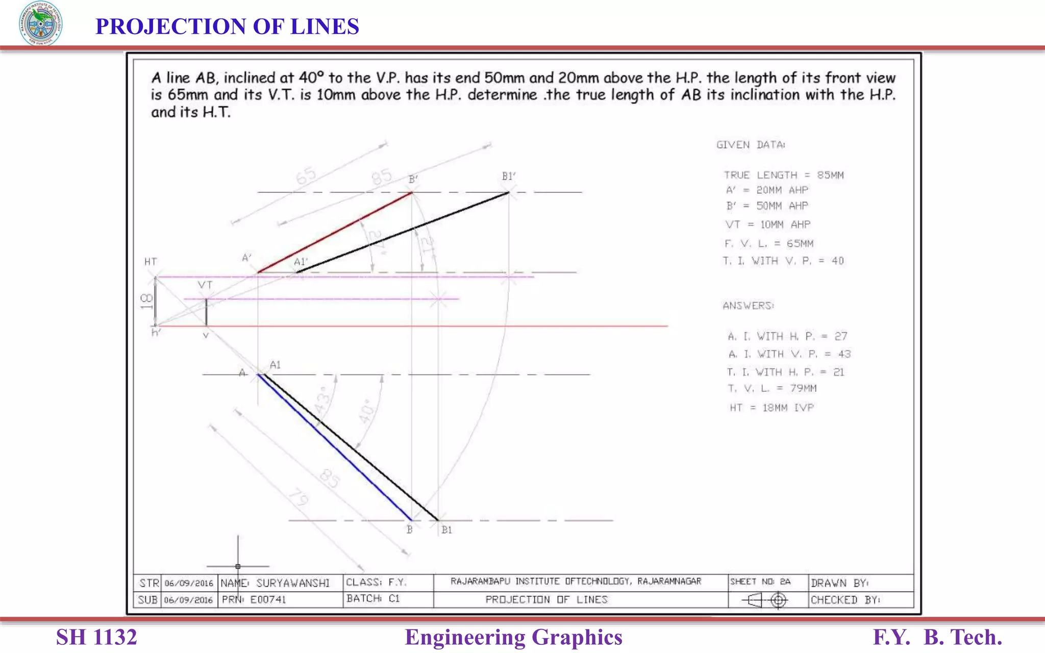
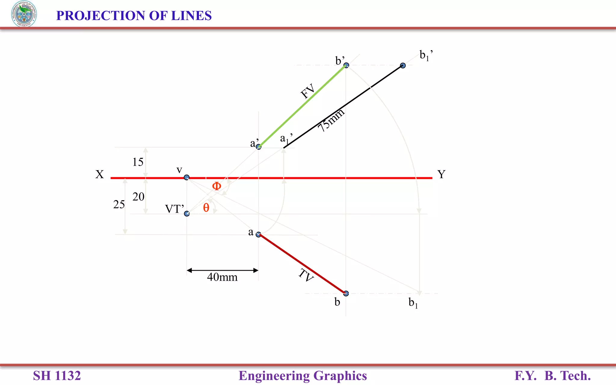
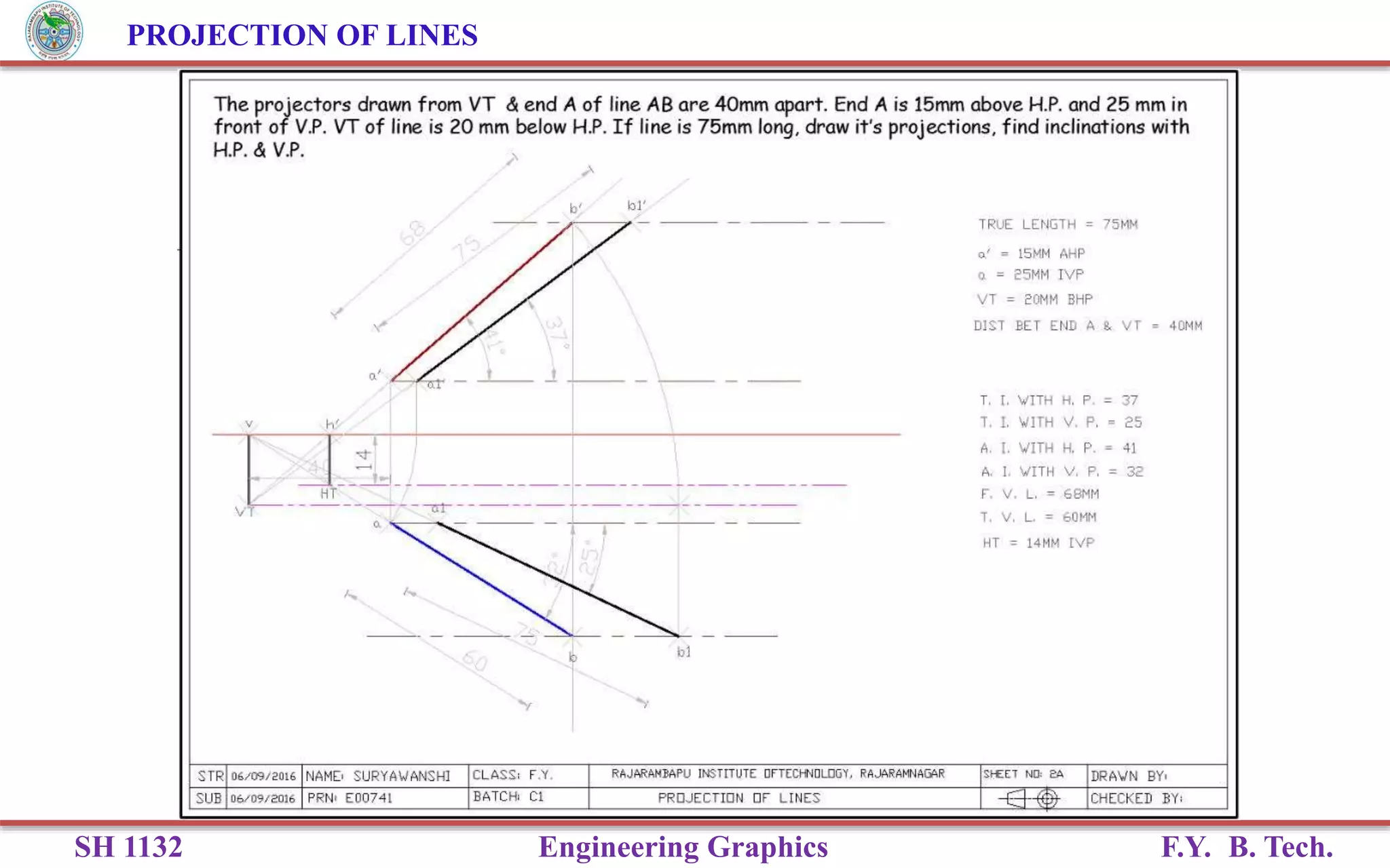
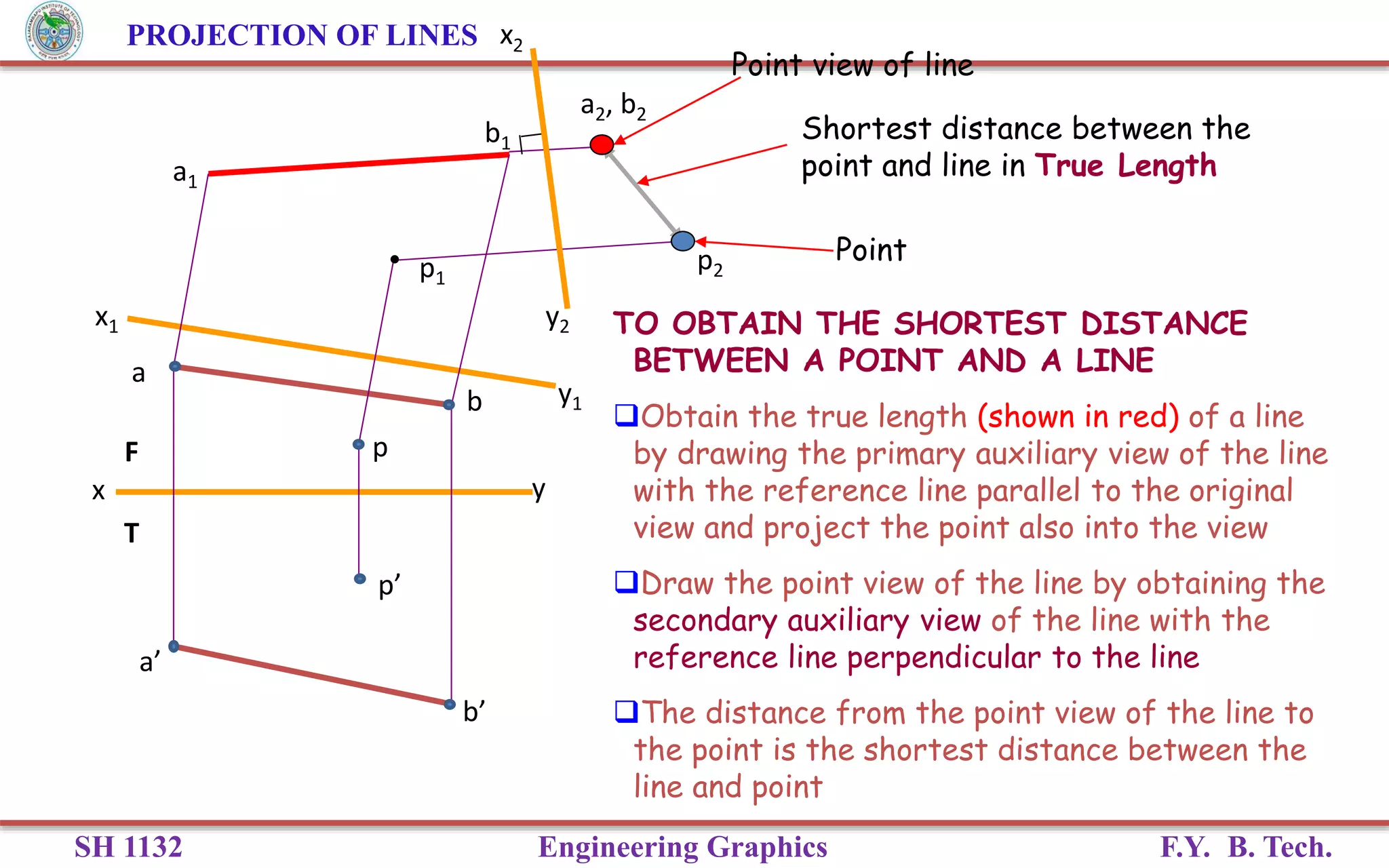
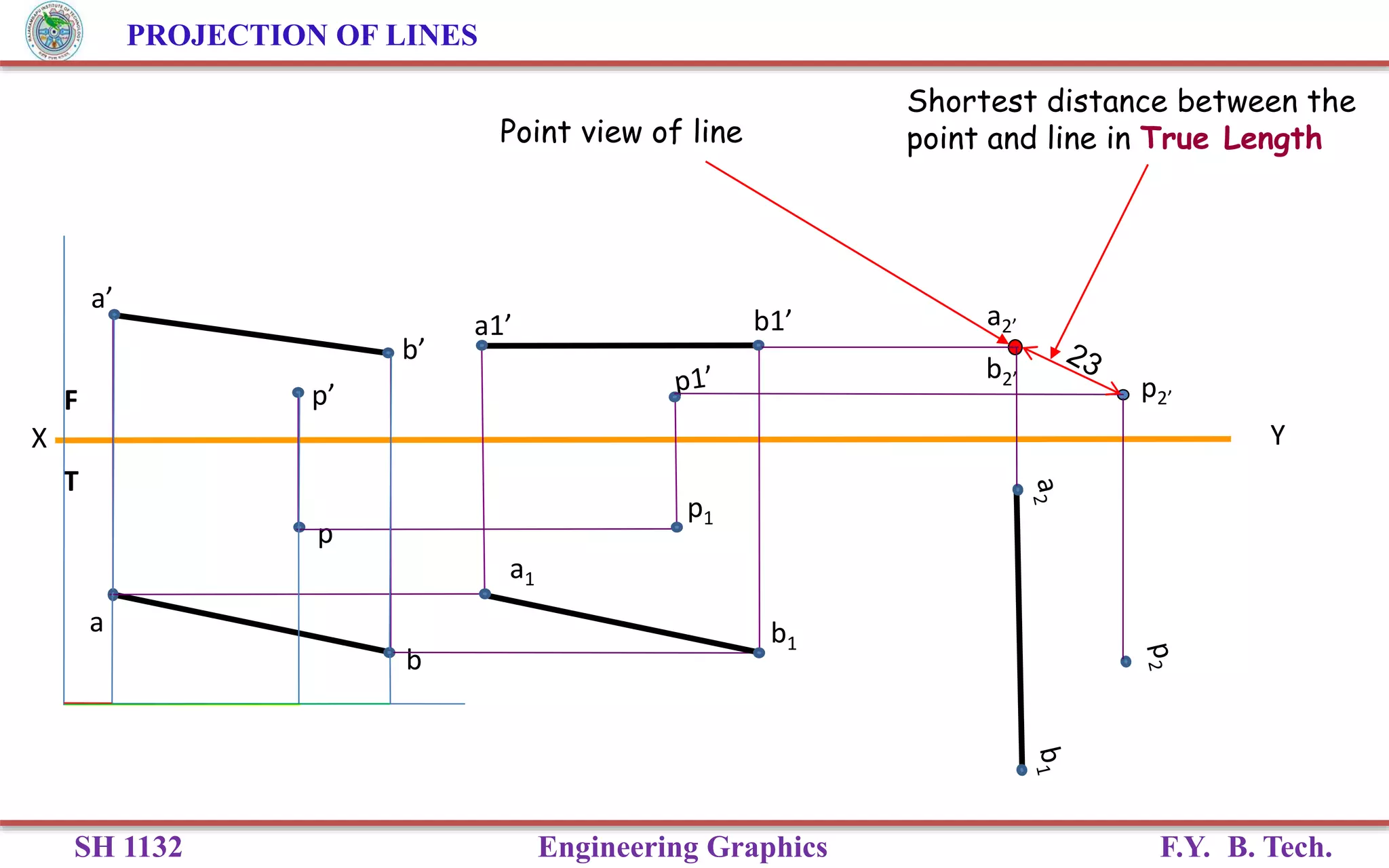
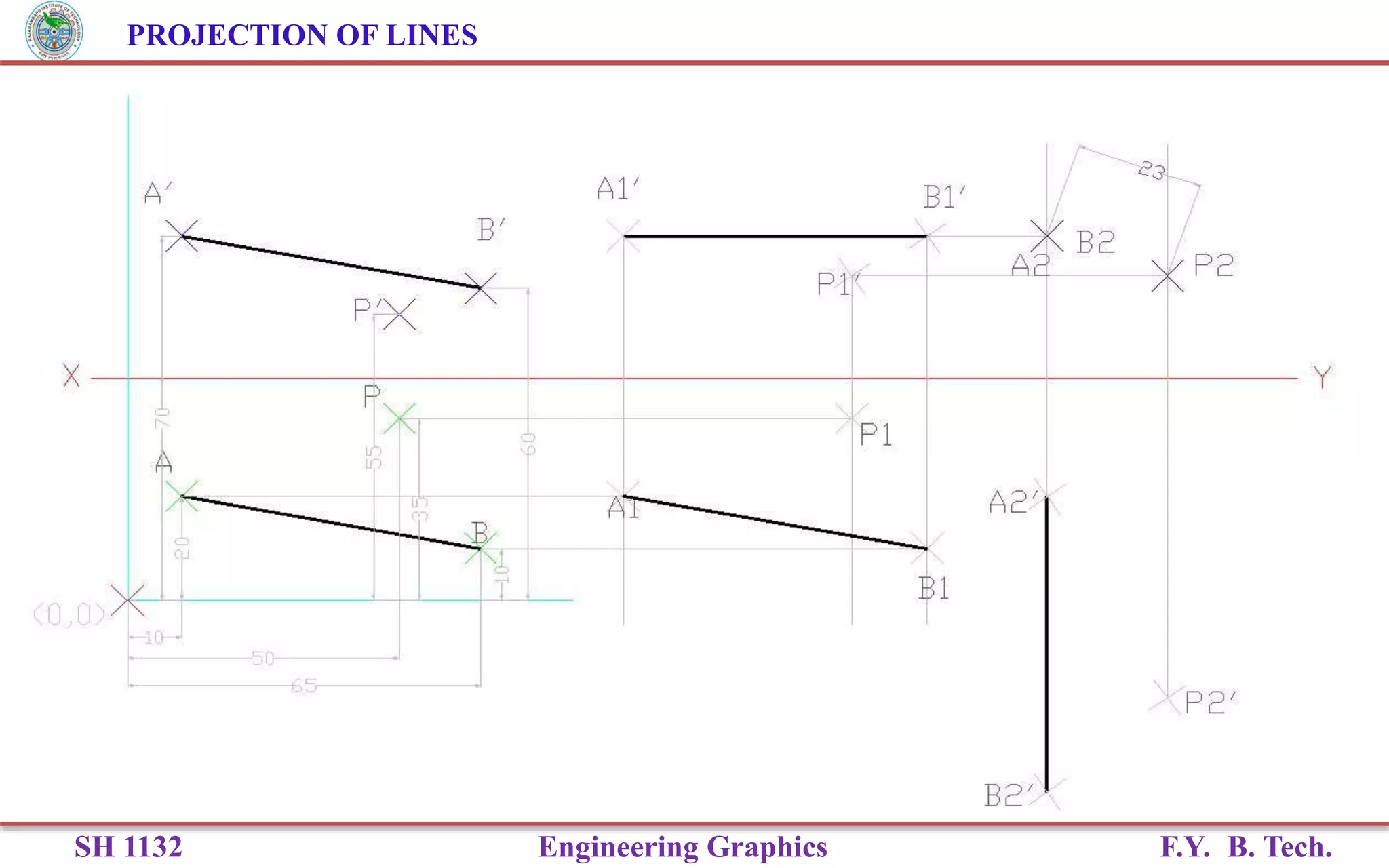
The document discusses the concepts and methods of projecting lines in engineering graphics. It defines key terms used in line projections such as true length, front view length, top view length, end projector distance, and inclinations. It presents different categories of line positions with respect to reference planes and provides examples of each with their orthographic projections. The document also contains several example problems demonstrating how to draw the projections of lines given information about their lengths, positions of endpoints, and inclinations to the planes. It describes the process for locating the horizontal and vertical traces of a line when given its projections.
introduction of engineering graphics ,projection of points,lines,planes,solids,section of solids,development of surfaces,isometric projection,perspective projection
Section of solids - ENGINEERING DRAWING/GRAPHICSAbhishek Kandare
Section of solids
THIS SLIDE CONTAINS WHOLE SYLLABUS OF ENGINEERING DRAWING/GRAPHICS. IT IS THE MOST SIMPLE AND INTERACTIVE WAY TO LEARN ENGINEERING DRAWING.SYLLABUS IS RELATED TO rajiv gandhi proudyogiki vishwavidyalaya / rajiv gandhi TECHNICAL UNIVERSITY ,BHOPAL.
Development of surfaces of solids -ENGINEERING DRAWING - RGPV,BHOPALAbhishek Kandare
Development of surfaces of solids
THIS SLIDE CONTAINS WHOLE SYLLABUS OF ENGINEERING DRAWING/GRAPHICS. IT IS THE MOST SIMPLE AND INTERACTIVE WAY TO LEARN ENGINEERING DRAWING.SYLLABUS IS RELATED TO rajiv gandhi proudyogiki vishwavidyalaya / rajiv gandhi TECHNICAL UNIVERSITY ,BHOPAL.
introduction of engineering graphics ,projection of points,lines,planes,solids,section of solids,development of surfaces,isometric projection,perspective projection
Projection of solids - ENGINEERING DRAWING/GRAPHICSAbhishek Kandare
Projection of solids
HIS SLIDE CONTAINS WHOLE SYLLABUS OF ENGINEERING DRAWING/GRAPHICS. IT IS THE MOST SIMPLE AND INTERACTIVE WAY TO LEARN ENGINEERING DRAWING.SYLLABUS IS RELATED TO rajiv gandhi proudyogiki vishwavidyalaya / rajiv gandhi TECHNICAL UNIVERSITY ,BHOPAL.
Download link: https://www.researchgate.net/publication/318852873_Engineering_Drawing_-_I
DOI: 10.13140/RG.2.2.22512.56328
An engineering drawing is a type of technical drawing, used to fully and clearly define requirements for engineered items, and is usually created in accordance with standardized conventions for layout, nomenclature, interpretation, appearance size, etc.
Its purpose is to accurately and unambiguously capture all the geometric features of a product or a component. The end goal of an engineering drawing is to convey all the required information that will allow a manufacturer to produce that component.
This is Mechnicial Engineering's subjrct technicial drawing slides
topic name is Projection of lines.
this would help you in how you draw front side and top view of a line.
Final project report on grocery store management system..pdfKamal Acharya
In today’s fast-changing business environment, it’s extremely important to be able to respond to client needs in the most effective and timely manner. If your customers wish to see your business online and have instant access to your products or services.
Online Grocery Store is an e-commerce website, which retails various grocery products. This project allows viewing various products available enables registered users to purchase desired products instantly using Paytm, UPI payment processor (Instant Pay) and also can place order by using Cash on Delivery (Pay Later) option. This project provides an easy access to Administrators and Managers to view orders placed using Pay Later and Instant Pay options.
In order to develop an e-commerce website, a number of Technologies must be studied and understood. These include multi-tiered architecture, server and client-side scripting techniques, implementation technologies, programming language (such as PHP, HTML, CSS, JavaScript) and MySQL relational databases. This is a project with the objective to develop a basic website where a consumer is provided with a shopping cart website and also to know about the technologies used to develop such a website.
This document will discuss each of the underlying technologies to create and implement an e- commerce website.
Cosmetic shop management system project report.pdfKamal Acharya
Buying new cosmetic products is difficult. It can even be scary for those who have sensitive skin and are prone to skin trouble. The information needed to alleviate this problem is on the back of each product, but it's thought to interpret those ingredient lists unless you have a background in chemistry.
Instead of buying and hoping for the best, we can use data science to help us predict which products may be good fits for us. It includes various function programs to do the above mentioned tasks.
Data file handling has been effectively used in the program.
The automated cosmetic shop management system should deal with the automation of general workflow and administration process of the shop. The main processes of the system focus on customer's request where the system is able to search the most appropriate products and deliver it to the customers. It should help the employees to quickly identify the list of cosmetic product that have reached the minimum quantity and also keep a track of expired date for each cosmetic product. It should help the employees to find the rack number in which the product is placed.It is also Faster and more efficient way.
Welcome to WIPAC Monthly the magazine brought to you by the LinkedIn Group Water Industry Process Automation & Control.
In this month's edition, along with this month's industry news to celebrate the 13 years since the group was created we have articles including
A case study of the used of Advanced Process Control at the Wastewater Treatment works at Lleida in Spain
A look back on an article on smart wastewater networks in order to see how the industry has measured up in the interim around the adoption of Digital Transformation in the Water Industry.
Sachpazis:Terzaghi Bearing Capacity Estimation in simple terms with Calculati...Dr.Costas Sachpazis
Terzaghi's soil bearing capacity theory, developed by Karl Terzaghi, is a fundamental principle in geotechnical engineering used to determine the bearing capacity of shallow foundations. This theory provides a method to calculate the ultimate bearing capacity of soil, which is the maximum load per unit area that the soil can support without undergoing shear failure. The Calculation HTML Code included.
Explore the innovative world of trenchless pipe repair with our comprehensive guide, "The Benefits and Techniques of Trenchless Pipe Repair." This document delves into the modern methods of repairing underground pipes without the need for extensive excavation, highlighting the numerous advantages and the latest techniques used in the industry.
Learn about the cost savings, reduced environmental impact, and minimal disruption associated with trenchless technology. Discover detailed explanations of popular techniques such as pipe bursting, cured-in-place pipe (CIPP) lining, and directional drilling. Understand how these methods can be applied to various types of infrastructure, from residential plumbing to large-scale municipal systems.
Ideal for homeowners, contractors, engineers, and anyone interested in modern plumbing solutions, this guide provides valuable insights into why trenchless pipe repair is becoming the preferred choice for pipe rehabilitation. Stay informed about the latest advancements and best practices in the field.
2. PROJECTION OF LINES
SH 1132 Engineering Graphics F.Y. B. Tech.
Notations used for Straight Line
True length of the line:
Denoted by Capital letters. e.g. AB=100 mm, means that true length of the line is
100 mm.
Front View Length:
Denoted by small letters. e.g. a’b’=70 mm, means that Front View Length is 70 mm.
Top View Length:
Denoted by small letters. e.g. ab=80 mm, means that Top View Length is 80 mm.
End Projector Distance:
It is the distance between two projectors passing through end points of F.V. & T.V.
measured parallel to XY line.
3. PROJECTION OF LINES
SH 1132 Engineering Graphics F.Y. B. Tech.
Inclination of Front View Length with XY :
It is denoted by α. e.g. Inclination of the Front View of the line with XY is given as
50º means that α = 50º.
Inclination of True Length of Line with V.P.:
It is denoted by Φ. e.g. Inclination of the line with V.P. is given as 40º means that Φ
= 40º.
Inclination of True Length of Line with H.P.:
It is denoted by θ. e.g. Inclination of the line with H.P. (or Ground) is given as 30º
means that θ = 30º.
Inclination of Top View Length with XY :
It is denoted by β. e.g. Inclination of the Top View of the line with XY is given as
30º means that β = 30º.
4. PROJECTION OF LINES
SH 1132 Engineering Graphics F.Y. B. Tech.
X
Y
X
Y
b’
a’
b
a
a,b
a’
b’
B
A
TV
FV
A
B
X Y
H.P.
V.P.
a’
b’
a b
FV
TV
X Y
H.P.
V.P.
a b
a’ b’FV
TV
For TV
For TV
FV is a vertical line
showing True Length &
TV is a point.
FV & TV both are
// to xy & both show
T. L.
1.
2.
A Line
perpendicular
to H.P.
&
// to V.P.
A Line
// to H.P.
&
// to V.P.
Orthographic Pattern
(Pictorial Presentation)
5. PROJECTION OF LINES
SH 1132 Engineering Graphics F.Y. B. Tech.
A Line inclined to H.P.
and
parallel to V.P.
(Pictorial presentation)
X
Y
A
B
b’
a’
b
a
A Line inclined to V.P.
and
parallel to H.P.
(Pictorial presentation)
Ø
a b
a’
b’
BA
Ø
X Y
H.P.
V.P.
T.V.
a b
a’
b’
X Y
H.P.
V.P.
Øa
b
a’ b’
TV
FV
TV inclined to xy
showing T.L & FV
parallel to xy.
3.
4.
FV inclined to xy showing
T.L & TV parallel to xy.
Orthographic Projections
True Length
True Length
6. PROJECTION OF LINES
SH 1132 Engineering Graphics F.Y. B. Tech.
X
Y
a’
b’
a b
B
A
For TV
T.V.
X
Y
a’
b’
a b
T.V.
For TV
B
A
X Y
H.P.
V.P.
a
b
FV
TV
a’
b’
A Line inclined to both
H.P. and V.P.
(Pictorial presentation)
5.
Note These Facts:-
Both FV & TV are inclined to xy.
(No view is parallel to xy)
Both FV & TV are reduced lengths.
(No view shows True Length)
Orthographic Projections
FV is seen on V.P. clearly.
To see TV clearly, H.P. is
rotated 900 downwards,
Hence it comes below xy.
On removal of object
i.e. Line AB
FV as a image on V.P.
TV as a image on H.P,
NOTE: a and b are NOT
the true angles
(inclinations) of the line
with the planes
7. PROJECTION OF LINES
SH 1132 Engineering Graphics F.Y. B. Tech.
Line in Different Positions with respect to H.P. & V.P.
CLASS A: Line perpendicular to (or in) one reference plane & hence parallel to
both the other planes
(1) Line perpendicular to P.P. & (hence) parallel to both H.P. & V.P.
(2) Line perpendicular to V.P. & (hence) parallel to both H.P. & P.P.
(3) Line perpendicular to H.P. & (hence) parallel to both V.P. & P.P.
8. PROJECTION OF LINES
SH 1132 Engineering Graphics F.Y. B. Tech.
CLASS B: Line parallel to (or in) one reference plane & inclined to other two
planes
(1) Line parallel to ( or in) V.P. & inclined to H.P. by .
(2) Line parallel to ( or in) H.P. & inclined to V.P. by .
(3) Line parallel to ( or in) P.P. & inclined to H.P. by & V.P. by .
Line in Different Positions with respect to H.P. & V.P.
9. PROJECTION OF LINES
SH 1132 Engineering Graphics F.Y. B. Tech.
CLASS C: Line inclined to all three reference planes ( Oblique lines )
Line inclined to H.P. by , to V.P. by and also inclined to profile plane.
Line in Different Positions with respect to H.P. & V.P.
10. PROJECTION OF LINES
SH 1132 Engineering Graphics F.Y. B. Tech.
SR.NO POSITION OF LINE FRONT VIEW TOP VIEW
1
LINE PERPENDICULAR TO H.P AND
PARALLEL TO V.P
VERTICAL LINE
SHOWING T.L
POINT
2
LINE PERPENDICULAR TO V.P AND
PARALLEL TO H.P
POINT
VERTICAL LINE
SHOWING T.L
3 LINE PARALLEL TO BOTH V.P & H.P
HORIZONTAL LINE
PARALLEL TO XY
SHOWING T.L
HORIZONTAL LINE
PARALLEL TO XY
SHOWING T.L
4
LINE PARALLEL TO H.P AND INCLINED
TO V.P AT ANGLE “Ѳ”
LINE PARALLEL TO XY
WITH APPARENT
LENGTH
INCLINED LINE
SHOWING TRUE LENGTH
5
LINE PARALLEL TO V.P AND INCLINED TO
H.P AT ANGLE“Ѳ”
INCLINED LINE
SHOWING TRUE LENGTH
LINE PARALLEL TO XY
WITH APPARENT
LENGTH
6
LINE INCLINED TO V.P AT ANGLE “Ø”
AND INCLINED TO H.P AT ANGLE“Ѳ”
INCLINED LINE
SHOWING APPARENT
LENGTH
INCLINED LINE
SHOWING APPARENT
LENGTH
11. PROJECTION OF LINES
SH 1132 Engineering Graphics F.Y. B. Tech.
PROBLEM 1:-
A Line AB, 90 mm long, is inclined to H.P. by 30° and inclined to V.P.
by 45º. The line is in first quadrant with Point A 15 mm above H.P. and 25
mm in front of V.P. Draw the projection of line AB.
12. PROJECTION OF LINES
SH 1132 Engineering Graphics F.Y. B. Tech.
2515
Φ
α
β
a’
a
b’ b1’
Y
X
b
b2
θ
Locus of b’
Locus of b
Data Given :-
(1) T.L.=90 mm
(2) Θ =30°
(3) Φ =45°
(4) Point A
15 above H.P.
25 mm in Front
of V.P.
Answers :-
(1) F.V.= 64 mm
(2) T.V = 78 mm
(3) α = 45°
(4) = 55°
b2’
b1
.
. Locus of a’
Locus of a
13. PROJECTION OF LINES
SH 1132 Engineering Graphics F.Y. B. Tech.
PROBLEM 2:-
Line AB is 75 mm long and it is 30o & 40o inclined to HP & VP
respectively. End A is 12 mm above HP and 10 mm in front of VP. Draw
projections. Line is in 1st quadrant.
14. PROJECTION OF LINES
SH 1132 Engineering Graphics F.Y. B. Tech.
a'
b'
a
b
X Y
b2’
b1
Ø
α
TL
FV
TV
b2
Locus of b’
Locus of b
TL
b1’
Locus of a’
Locus of a
15. PROJECTION OF LINES
SH 1132 Engineering Graphics F.Y. B. Tech.
PROBLEM 3:-
F.V of line AB is 50o inclined to XY and measures 55 mm long,
while it’s TV is 60o inclined to XY line. If end A is 10 mm above HP and
15 mm in front of VP, draw it’s projections, find True Length,
inclinations of line with Hp & Vp.
16. PROJECTION OF LINES
SH 1132 Engineering Graphics F.Y. B. Tech.
X
a'
Y
a
b'
500
b
600
b1
b1’
b2
b2’
Locus of b’
Locus of b
Locus of a’
Locus of a
17. PROJECTION OF LINES
SH 1132 Engineering Graphics F.Y. B. Tech.
PROBLEM 4:-
Line AB is 75 mm long .It’s FV and TV measure 50 mm & 60
mm long respectively. End A is 10 mm above HP and 15 mm in front
of VP. Draw projections of line AB if end B is in first quadrant.
Find angle with HP and VP.
18. PROJECTION OF LINES
SH 1132 Engineering Graphics F.Y. B. Tech.
X Y
a'
a
b’
b1
b2'
b
b2
b1' Locus of b’
Locus of b
Locus of a
Locus of a’
19. PROJECTION OF LINES
SH 1132 Engineering Graphics F.Y. B. Tech.
PROBLEM 5:-
T.V. of a 75 mm long Line CD, measures 50 mm. End C is in HP
and 50 mm in front of VP. End D is 15 mm in front of VP and it is
above HP. Draw projections of CD and find angles with HP and VP.
20. PROJECTION OF LINES
SH 1132 Engineering Graphics F.Y. B. Tech.
X Y
c'
c
Locus of d
d d1
d’
Locus of d’d1’
d2’
Locus of c
Locus of c’
21. PROJECTION OF LINES
SH 1132 Engineering Graphics F.Y. B. Tech.
PROBLEM 6:-
The top view of a 75mm long line CD measures 50 mm. C is 50
mm in front of the VP & 15mm below the HP. D is 15 mm in front of the
VP & is above the HP. Draw the FV of CD & find its inclinations with
the HP and the VP.
22. PROJECTION OF LINES
SH 1132 Engineering Graphics F.Y. B. Tech.
X Y
15
50
c’
c
Locus of c’d
d1
d1’d’
Ø=48°
Ans: Ø=48°
d2
θ=28°
Ans: θ=28°
Locus of d’
Locus of c
Locus of d
23. PROJECTION OF LINES
SH 1132 Engineering Graphics F.Y. B. Tech.
PROBLEM 7:-
A line PQ 100 mm long is inclined at 30º to the H.P. and at 45º
to the V.P. Its mid point is in the V.P. and 20 mm above the H.P. Draw
its projections, if its end P is in the third quadrant and Q is in the
first quadrant.
24. PROJECTION OF LINES
SH 1132 Engineering Graphics F.Y. B. Tech.
X Y
20
m’
m
30°
q1’
p1’
q2
p2
q2’
q’
p’
q
p
q2
p1
p2’
45°
25. PROJECTION OF LINES
SH 1132 Engineering Graphics F.Y. B. Tech.
TRACES OF A LINE
Definition: When a line is inclined to a plane, it will meet that plane, produced if
necessary. The point where the line or line produced meets the plane is
called trace.
Horizontal Trace: The point of intersection of the inclined line with the H.P. is
called Horizontal Trace or simply H.T.
A line itself or it’s extension, where ever touches H.P., That point is called
trace of the line on H.P. ( It is called H.T.)
H.T.:- It is a point on HP.
It’s FV comes on XY line (point h).
26. PROJECTION OF LINES
SH 1132 Engineering Graphics F.Y. B. Tech.
Similarly, a line itself or it’s extension, where ever touches V.P., That point is
called trace of the line on V.P.( It is called V.T.)
Traces of A line
Vertical Trace: The point of intersection of the inclined line with the V.P. is called
Vertical Trace or simply V.T.
V.T.:- It is a point on VP.
It’s TV comes on XY line (point V).
27. PROJECTION OF LINES
SH 1132 Engineering Graphics F.Y. B. Tech.
1. Begin with FV. Extend FV up to XY line.
2. Name this point h
( as it is a FV of a point in HP)
3. Draw one projector from h’.
4. Now extend TV to meet this projector.
This point is HT
STEPS TO LOCATE HT.
(WHEN PROJECTIONS ARE GIVEN.)
1. Begin with TV. Extend TV up to XY line.
2. Name this point v
( as it is a TV of a point in VP)
3. Draw one projector from v.
4. Now extend Fv to meet this projector.
This point is VT
STEPS TO LOCATE VT.
(WHEN PROJECTIONS ARE GIVEN.)
h
HTVT
v
a’
x y
a
b’
b
Observe & note :-
1. Points h & v always on x-y line.
2. VT & v always on one projector.
3. HT & h always on one projector.
4. FV - h- VT always co-linear.
5. TV - v - HT always co-linear.
28. PROJECTION OF LINES
SH 1132 Engineering Graphics F.Y. B. Tech.
PROBLEM 8:-
Point A of a line AB is 15mm above the H. R. P. and 20mm in
front of the F. R. P. and the point B is 50mm above H. R. P. and 75mm
in front of the F. R. P. If the projections through A and B are 50mm
apart, complete the projections of AB, determine the H.T., V.T., the
true inclinations of the line with F. R. P. and with H. R. P.
29. PROJECTION OF LINES
SH 1132 Engineering Graphics F.Y. B. Tech.
a'
X Y
a
15
20
50
50
b'
75
b1’
b1
θ α
Φ β
h’
HT
v
VT
’
b
θ: True inclination of the line
with HP = 24º
α : Inclination of FV of the
line with HP/ XY
Ø: True inclination of the line
with VP = 41º
β : Inclination of TV of the
line with VP/ XY
b2’
b2
H.T. : Behind the F.R.P.
V.T. : Above the H.R.P.
15
20
50
50
75
30. PROJECTION OF LINES
SH 1132 Engineering Graphics F.Y. B. Tech.
PROBLEM 9:
A line AB, 70mm long, has its end A 15mm above HP and
20mm in front of VP. It is inclined at 30° to HP and 45°to VP.
Draw its projections and mark its traces.
31. PROJECTION OF LINES
SH 1132 Engineering Graphics F.Y. B. Tech.
X Y
15
a’
20
b1’
a
b2
30°
45°
b1
b
b’
b2’
h’
HT
v
VT’
32. PROJECTION OF LINES
SH 1132 Engineering Graphics F.Y. B. Tech.
PROBLEM 10:
The projectors of the ends of a line AB are 50mm apart.
The end A is 20mm above the H.P and 30mm in front of V.P. The
end B is 10mm below H.P. and 40mm behind the V.P. Determine
the true length and traces of AB, and its inclination with the two
planes
33. PROJECTION OF LINES
SH 1132 Engineering Graphics F.Y. B. Tech.
X Y
50
20
a’
30
a
40
b
10
b’
b1
Ans. θ=20º
20º
b2’
b2
50º
Ans. Ø=50º
h’
HT
v
VT’
34. PROJECTION OF LINES
SH 1132 Engineering Graphics F.Y. B. Tech.
PROBLEM 11:
One end of line AB is 10mm above Hp and other end is 100 mm
in-front of V.P. It’s FV is 45° inclined to XY while it’s HT & VT are
45mm and 30 mm below XY respectively. Draw projections and find TL
with it’s inclinations with H.P. & V.P.
35. PROJECTION OF LINES
SH 1132 Engineering Graphics F.Y. B. Tech.
a’
b’
30
45
10
LOCUS OF b’ & b’1
X Y
450
VT’
v
HT
h’
LOCUS OF b & b1
100
a
b
b’1
b1
36. PROJECTION OF LINES
SH 1132 Engineering Graphics F.Y. B. Tech.
PROBLEM 12:
A line AB, inclined at 40º to the V.P. has its end 50mm and 20mm
above the H.P. the length of its front view is 65mm and its V.T. is
10mm above the H.P. determine .the true length of AB its inclination
with the H.P. and its H.T.
37. PROJECTION OF LINES
SH 1132 Engineering Graphics F.Y. B. Tech.
X Y
50 b’
20
a’
10
VT’
h’
b2’
v40º
b2
b
a
b1
b1’
21º HT
Ans:
TL = 85 mm,
θ = 21º
HT is 17 mm behind VP
39. PROJECTION OF LINES
SH 1132 Engineering Graphics F.Y. B. Tech.
PROBLEM 13:
The projectors drawn from VT & end A of line AB are
40mm apart. End A is 15mm above H.P. and 25 mm in front of V.P.
VT of line is 20 mm below H.P. If line is 75mm long, draw it’s
projections, find inclinations with H.P. & V.P.
40. PROJECTION OF LINES
SH 1132 Engineering Graphics F.Y. B. Tech.
X Y
40mm
15
20
25
v
VT’
a’
a
a1’
b1’
b’
b b1
42. PROJECTION OF LINES
SH 1132 Engineering Graphics F.Y. B. Tech.
Shortest distance between Point and Line
43. PROJECTION OF LINES
SH 1132 Engineering Graphics F.Y. B. Tech.
PROBLEM : 14
Find out the shortest distance of point P from Line AB. Complete the
projections. If A(10,20,70), B(65,10,60) and P(50,35,55).
44. PROJECTION OF LINES
SH 1132 Engineering Graphics F.Y. B. Tech.
a’
b’
a
p’
p
Shortest distance between the
point and line in True Length
Point
Point view of line
TO OBTAIN THE SHORTEST DISTANCE
BETWEEN A POINT AND A LINE
Obtain the true length (shown in red) of a line
by drawing the primary auxiliary view of the line
with the reference line parallel to the original
view and project the point also into the view
Draw the point view of the line by obtaining the
secondary auxiliary view of the line with the
reference line perpendicular to the line
The distance from the point view of the line to
the point is the shortest distance between the
line and point
a2, b2
p2
T
F
x
x1
y1
y2
y
b
a1
p1
b1
45. PROJECTION OF LINES
SH 1132 Engineering Graphics F.Y. B. Tech.
a
b
a’
p
p’
b2’
p2’
T
F
X Y
b’
a1’ b1’
p1
a1
b1
a2’
Shortest distance between the
point and line in True LengthPoint view of line
47. PROJECTION OF LINES
SH 1132 Engineering Graphics F.Y. B. Tech.
Projections of Perpendicular Line
48. PROJECTION OF LINES
SH 1132 Engineering Graphics F.Y. B. Tech.
PROBLEM 15:
Line PQ is perpendicular to line AB. End Q of line PQ is on AB. Complete
the projections. If A(10,20,70), B(65,10,60) and P(50,35,55).
49. PROJECTION OF LINES
SH 1132 Engineering Graphics F.Y. B. Tech.
a’
b’
a
p’
p
T
F
x
x1
y1
y
b
a1
p1
b1q1
Point on line at
shortest distance
q
q’
50. PROJECTION OF LINES
SH 1132 Engineering Graphics F.Y. B. Tech.
a
b
a’
p
p’
T
F
X Y
b’
a1’ b1’
p1
a1
b1
H.P.
V.P.
q1
q’
q
52. PROJECTION OF LINES
SH 1132 Engineering Graphics F.Y. B. Tech.
Projection of Lines
Projection of intersecting lines
When the lines are intersecting, the point of intersection lies on both the lines
and hence these lines have no shortest distance between them.
53. PROJECTION OF LINES
SH 1132 Engineering Graphics F.Y. B. Tech.
Projection of Lines
PROBLEM 16:
Determine the angle of intersection between Line AB and Line CD. if
A(25, 30, 55), B(65, 05, 90), C(10, 15, 75), and D(50, 40, y2)
54. PROJECTION OF LINES
SH 1132 Engineering Graphics F.Y. B. Tech.
Primary
Auxilary
View
Parallel
True length
x1
y1
a1
b1
c1 d1
T
F
TRUE LENGTH OF
BOTH LINES
True Angle between
the two lines
x y
a’
a
c’ b’
b
d’
c
d
x2
a2 ,b2
c2
Point view of
one line SECONDARY AUXILIARY VIEW
d2
TERTIARY AUXILIARY VIEW
Parallel
x3
y3
b3
a3
c3
d3
55. PROJECTION OF LINES
SH 1132 Engineering Graphics F.Y. B. Tech.
X
a’
a
c’
b’
b
d’
c
d a1
b1
c1
d1
c2’
b2’
a2’
d2’
c3
d3
a3
b3
True length of
both lines
True Angle
between the
two lines
Y
Angle between the line AB and line CD is 93°
Point view of
one line AB
True length
57. PROJECTION OF LINES
SH 1132 Engineering Graphics F.Y. B. Tech.
PROBLEM 17:
Find the angle between two intersecting lines AB and CD, if A(30,30,60),
B(70,45,80), C(20,40,80) and D(65, 30, y2).
59. PROJECTION OF LINES
SH 1132 Engineering Graphics F.Y. B. Tech.
Problem 18:
Find the angle between EF and FG if E(15, 10, 55), G(75, 40, 90),
and F(40, 40, 50)
61. PROJECTION OF LINES
SH 1132 Engineering Graphics F.Y. B. Tech.
Projection of Lines
Projections of skew lines
Non-parallel and non-intersecting lines are called Skew Lines.
The parallel lines and the skew lines have a shortest distance between them.
62. PROJECTION OF LINES
SH 1132 Engineering Graphics F.Y. B. Tech.
Problem 19:
Find the shortest distance between AB and CD lines if A(10, 25,
60), B(50, 45, 70), C(10, 10, 75), and D(50, 05, 60).
63. PROJECTION OF LINES
SH 1132 Engineering Graphics F.Y. B. Tech.
a
a’
b
b’
d’
c’
d
c
b2
a2
d2, c2
•Find the true length of one of the lines and
project its point view using auxiliary plane
method
•Project the other line also in each view
•The perpendicular distance between the
point view of one line and the other line is
the required shortest distance between the
two lines
Required distance
* Point can be projected back into the
other planes
T
F
Primary auxiliary view
Secondary auxiliary view
DISTANCE BETWEEN 2 LINES
a1
c1
d1TL
X1
Y1
X2
Y2
Parallel
Perpendicular
65. PROJECTION OF LINES
SH 1132 Engineering Graphics F.Y. B. Tech.
Projections of Parallel lines
66. PROJECTION OF LINES
SH 1132 Engineering Graphics F.Y. B. Tech.
PROBLEM 20:
Line CD 40mm long is parallel to AB and 20mm away from it. Complete the
projections of line CD. A(20, 10, 55), C(10, 10, y2), B(55, 45, 90)
68. PROJECTION OF LINES
SH 1132 Engineering Graphics F.Y. B. Tech.
F
X Y
T
X1
Y1
a
a'
b
b'
c1
X2
Y2
c
c'
b2
b1
a2
a1
d2
d1
c2
d'
d
Parallel
Perpendicular
Primary
Auxiliary
View
69. PROJECTION OF LINES
SH 1132 Engineering Graphics F.Y. B. Tech.
Problem 21:
AB and CD are parallel to each other. Complete the projections of
line AB, if it is 25 mm away from CD. Length of AB= 35 mm A(30, 10, z),
C(15, 25, 55), D(55, 45, 75)
70. PROJECTION OF LINES
SH 1132 Engineering Graphics F.Y. B. Tech.
Problem 22:
Line makes 30º with FRP and its TL is 30mm. It is parallel to AB
and 15 mm away from it. Draw the projections of CD if A(10, 50, 65), B(60,
y1, 80), C(20, y1, 80).
71. PROJECTION OF LINES
SH 1132 Engineering Graphics F.Y. B. Tech.
PROJECTIONS OF
STRAIGHT LINES