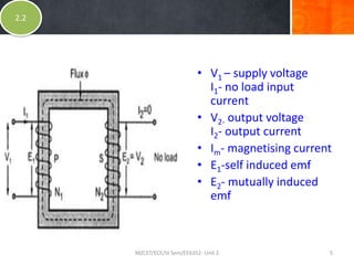
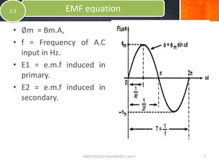
SUMMARY
• In last class, we discussed about the function
of transformers.
• Basic principle behind the operation of
transformer.
• Electromagnetic induction and mutual
induction.
• Types of transformers based on some
properties such as current, voltage and
winding.
Ideal Transformers
• Zero leakage flux:
-Fluxes produced by the primary and secondary
currents are confined within the core
• The windings have no resistance:
- Induced voltages equal applied voltages
2.2
MZCET/ECE/III Sem/EE6352- Unit 2 3
Ideal Transformers
• The core has infinite permeability
1. Reluctance of the core is zero
2. Negligible current is required to establish
magnetic flux
• Loss-less magnetic core
No hysteresis or eddy currents
2.2
MZCET/ECE/III Sem/EE6352- Unit 2 4
Ideal transformer
• V1 – supply voltage
I1- no load input
current
• V2- output voltage
I2- output current
• Im- magnetising current
• E1-self induced emf
• E2- mutually induced
emf
2.2
MZCET/ECE/III Sem/EE6352- Unit 2 5
Let
• N1 = Number of turns in primary windings.
• N2 = Number of turns in second windings.
• ∅m =flux.
• ∅m = Maximum flux in the core in Webbers.
EMF equation of Transformer
2.3
MZCET/ECE/III Sem/EE6352- Unit 2 6
• ∅m = Bm.A,
• f = Frequency of A.C
input in Hz.
• E1 = e.m.f induced in
primary.
• E2 = e.m.f induced in
secondary.
EMF equation2.3
MZCET/ECE/III Sem/EE6352- Unit 2 7
• As shown in fig- flux increases from its zero
value to maximum value Øm in one quarter of
the cycle i.e. in ¼ second.
• Average rate of change of flux = (Øm / ¼f.)
= 4f Øm Wb/s or volt.
EMF equation2.3
MZCET/ECE/III Sem/EE6352- Unit 2 8
• Average e.m.f /per turn = 4f Øm volt.
• If flux Øm varies sinusoidally, then r.m.s value of
induced .e.m.f is obtained by multiplying the
average value with form factor.
EMF equation
MZCET/ECE/III Sem/EE6352- Unit 2 9
2.3
• Form factor =r.m.s value =1.11
• r.m.s value of e.m.f/turn = 1.11*4 f Øm
= 4.44f Øm volt
• now r.m.s value of the induced e.m.f in the whole primary
winding.=
( induced e.m.f/turn)*number of primary turns
EMF equation2.3
MZCET/ECE/III Sem/EE6352- Unit 2 10
• E1=4.44fN1Øm…………………………(1)
• E1 = 4.44fN1BmA.
(Øm= BmA)
Similarly, r.m.s value of the e.m.f. induced in
secondary is,
• E2 = 4.44fN2 Øm
EMF equation2.3
MZCET/ECE/III Sem/EE6352- Unit 2 11
• E2 = 4.44fN2BmA.……..(2)
(Øm= BmA)
It’s seen from (1) and (2) that
E1/N1=E2/N2= = 4.44f Øm.
EMF equation2.3
MZCET/ECE/III Sem/EE6352- Unit 2 12
Ideal transformer

Ideal transformer

  • 2.
    SUMMARY • In lastclass, we discussed about the function of transformers. • Basic principle behind the operation of transformer. • Electromagnetic induction and mutual induction. • Types of transformers based on some properties such as current, voltage and winding.
  • 3.
    Ideal Transformers • Zeroleakage flux: -Fluxes produced by the primary and secondary currents are confined within the core • The windings have no resistance: - Induced voltages equal applied voltages 2.2 MZCET/ECE/III Sem/EE6352- Unit 2 3
  • 4.
    Ideal Transformers • Thecore has infinite permeability 1. Reluctance of the core is zero 2. Negligible current is required to establish magnetic flux • Loss-less magnetic core No hysteresis or eddy currents 2.2 MZCET/ECE/III Sem/EE6352- Unit 2 4
  • 5.
    Ideal transformer • V1– supply voltage I1- no load input current • V2- output voltage I2- output current • Im- magnetising current • E1-self induced emf • E2- mutually induced emf 2.2 MZCET/ECE/III Sem/EE6352- Unit 2 5
  • 6.
    Let • N1 =Number of turns in primary windings. • N2 = Number of turns in second windings. • ∅m =flux. • ∅m = Maximum flux in the core in Webbers. EMF equation of Transformer 2.3 MZCET/ECE/III Sem/EE6352- Unit 2 6
  • 7.
    • ∅m =Bm.A, • f = Frequency of A.C input in Hz. • E1 = e.m.f induced in primary. • E2 = e.m.f induced in secondary. EMF equation2.3 MZCET/ECE/III Sem/EE6352- Unit 2 7
  • 8.
    • As shownin fig- flux increases from its zero value to maximum value Øm in one quarter of the cycle i.e. in ¼ second. • Average rate of change of flux = (Øm / ¼f.) = 4f Øm Wb/s or volt. EMF equation2.3 MZCET/ECE/III Sem/EE6352- Unit 2 8
  • 9.
    • Average e.m.f/per turn = 4f Øm volt. • If flux Øm varies sinusoidally, then r.m.s value of induced .e.m.f is obtained by multiplying the average value with form factor. EMF equation MZCET/ECE/III Sem/EE6352- Unit 2 9 2.3
  • 10.
    • Form factor=r.m.s value =1.11 • r.m.s value of e.m.f/turn = 1.11*4 f Øm = 4.44f Øm volt • now r.m.s value of the induced e.m.f in the whole primary winding.= ( induced e.m.f/turn)*number of primary turns EMF equation2.3 MZCET/ECE/III Sem/EE6352- Unit 2 10
  • 11.
    • E1=4.44fN1Øm…………………………(1) • E1= 4.44fN1BmA. (Øm= BmA) Similarly, r.m.s value of the e.m.f. induced in secondary is, • E2 = 4.44fN2 Øm EMF equation2.3 MZCET/ECE/III Sem/EE6352- Unit 2 11
  • 12.
    • E2 =4.44fN2BmA.……..(2) (Øm= BmA) It’s seen from (1) and (2) that E1/N1=E2/N2= = 4.44f Øm. EMF equation2.3 MZCET/ECE/III Sem/EE6352- Unit 2 12