UNIT - IIIELECTRICAL SYSTEMS
SINGLE / THREE PHASE SUPPLY - PROTECTIVE DEVICES IN ELECTRICAL
INSTALLATION - ISI SPECIFICATIONS - TYPES OF WIRES, WIRING SYSTEMS AND
THEIR CHOICE - PLANNING ELECTRICAL WIRING FOR BUILDING INTERIORS -
MAIN AND DISTRIBUTION BOARDS - TYPICAL ELECTRICAL LAYOUT FOR
INTERIORS
2.
INTRODUCTION
• Since theend of the nineteenth century virtually all buildings are provided with electric
lightings installation for use at night. With the advent of fluorescent lamp that is compatible with
daylight, cheap to run and not emitting heat gain in buildings, it made possible to install electric
lighting supplementing day light and in extreme cases provide the only source of light in a
windowless environment.
• Several factors can exercise a critical influence on the success of lighting installations apart
from proper level of illumination on the work plane.
3.
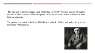
The first useof electric supply were established in 1882 by Thomas Edison, Thereafter
there have been constant effort throughout the world to set-up power stations for more
than one purposes.
The power generation in India in 1947-48 was only 4.1 billion and today we generate
more than 600 billion kw
4.
BASICS OF ELECTRICITY
•Electric current : The current is defined as the rate of flow of charges across any cross sectional
area of a conductor.
• Drift velocity : It is defined as the velocity with which free electrons get drifted towards the
positive terminal, when an electric field is applied.
• Ohm’s Law : At a constant temperature, the steady current flowing through a conductor is
directly proportional to the potential difference between the two ends of the conductor. V-
Voltage I-Current.
• Resistance : The opposition that a material presents to the flow of electrical charges is called
resistance.
• The unit for electrical resistance is the ohm (Ώ).
5.
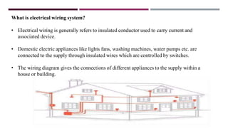
What is electricalwiring system?
• Electrical wiring is generally refers to insulated conductor used to carry current and
associated device.
• Domestic electric appliances like lights fans, washing machines, water pumps etc. are
connected to the supply through insulated wires which are controlled by switches.
• The wiring diagram gives the connections of different appliances to the supply within a
house or building.
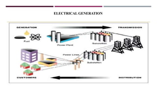
Electric Generator
• Electricityis generated from the stored energy of water that makes turbine run and
generate electricity.
• The other method includes fuels (Coal, diesel or gas) to fire boilers and pass stream and
generate electricity through generators.
• Transformer step up several thousands or even hundreds of thousands of volts before it is
supplied to the transmission lines or cable.
• By transmitting electricity at high voltages less power is lost in the cables.
• At the receiving end of voltage is stepped down by transforms in local sub-stations to
consumers at 240 volts.
8.
1.NEUTRAL:
1. Definition: Theneutral wire serves as the return path for an AC circuit. It carries current
under normal conditions.
2. Purpose: Balances the load and completes the circuit.
3. Current Flow: In normal situations, it doesn’t carry any significant current. However, in case
of phase current imbalance, it might carry a fraction of the phase current or even double it.
4. Charging: A neutral wire is always charged.
5. Reference Point: Also known as a reference point.
6. Connection: Connected to the main power wiring.
7. Example: Your home’s electrical outlets use the neutral wire.
9.
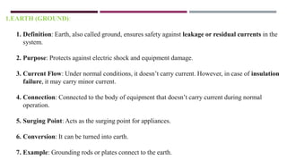
1.EARTH (GROUND):
1. Definition:Earth, also called ground, ensures safety against leakage or residual currents in the
system.
2. Purpose: Protects against electric shock and equipment damage.
3. Current Flow: Under normal conditions, it doesn’t carry current. However, in case of insulation
failure, it may carry minor current.
4. Connection: Connected to the body of equipment that doesn’t carry current during normal
operation.
5. Surging Point: Acts as the surging point for appliances.
6. Conversion: It can be turned into earth.
7. Example: Grounding rods or plates connect to the earth.
10.
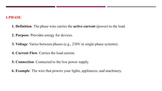
1.PHASE:
1. Definition: Thephase wire carries the active current (power) to the load.
2. Purpose: Provides energy for devices.
3. Voltage: Varies between phases (e.g., 230V in single-phase systems).
4. Current Flow: Carries the load current.
5. Connection: Connected to the live power supply.
6. Example: The wire that powers your lights, appliances, and machinery.
11.
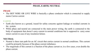
PHASE, EARTH, NEUTRAL
PHASE
•The HOT WIRE OR LIVE WIRE is basically a phase conductor which is connected to supply
mains Carries current
EARTH
• Earth also known as a ground, isused for safety concerns against leakage or residual currents in
the system.
• While phase and neutral are connected to the main power wiring, the earth is connected to the
body of equipment that doesn’t carry current in normal conditions but is supposed to carry some
minor current in case of any insulation failure.
NEUTRAL
• Neutral is there turn path for an AC circuit that carries current in normal conditions. This current
could be primarily because of the phase current imbalance.
• The magnitude of this current is a fraction of the phase current or, in a few cases, even double the
phase current.
12.
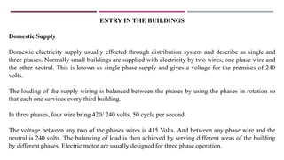
ENTRY IN THEBUILDINGS
Domestic Supply
Domestic electricity supply usually effected through distribution system and describe as single and
three phases. Normally small buildings are supplied with electricity by two wires, one phase wire and
the other neutral. This is known as single phase supply and gives a voltage for the premises of 240
volts.
The loading of the supply wiring is balanced between the phases by using the phases in rotation so
that each one services every third building.
In three phases, four wire bring 420/ 240 volts, 50 cycle per second.
The voltage between any two of the phases wires is 415 Volts. And between any phase wire and the
neutral is 240 volts. The balancing of load is then achieved by serving different areas of the building
by different phases. Electric motor are usually designed for three phase operation.
13.
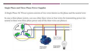
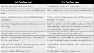
Single Phase andThree Phase Power Supplies
A Single Phase AC Power system consists of two wires known as the phase and the neutral wire.
In case a three phase system, you use either three wires or four wires for transmitting power (no
neutral in three wire three phase power and all the three wires are phases).
14.
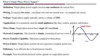
What is SinglePhase Power Supply?
•Definition: Single-phase power supply involves one conductor for current flow.
•Wiring: It requires two wires—one phase wire and one neutral wire—to complete the circuit.
•Voltage: Single-phase supply typically carries a voltage of 230V.
•Applications: It is commonly used for small appliances like fans, coolers, grinders, and heaters.
•Wave Shape: Single-phase power has a single AC waveform.
•Network Complexity: The network is simple, consisting of just two wires.
•Power Transfer Capability: Minimum compared to three-phase.
•Power Failure: Single-phase systems do not experience complete power loss.
•Efficiency: Less efficient due to limited power transfer.
•Example: Your household electrical outlets operate on single-phase power
15.
Advantages
•It is verycommon form of power supply to most small power requirement. Almost all residential
supplies are single phase supplies as the domestic appliances require a small amount of power to run
lights, fans, coolers, heaters, small air conditioners etc.
•The design and operation of a single phase power supply system is often simple.
•Depending on the region, a single phase supply is sufficient for loads up to 2500 Watts.
Disadvantages
•Small single phase motors (usually less than 1kW) cannot start directly with the help of a single phase
supply as there isn’t sufficient initial torque for the motor. So, additional circuitry like a Motor Starters
(like a starter capacitor in fans and pumps) are needed for proper operation.
•Heavy loads like industrial motors and other equipment cannot be run on a single phase supply.
16.
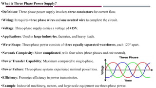
What is ThreePhase Power Supply?
•Definition: Three-phase power supply involves three conductors for current flow.
•Wiring: It requires three phase wires and one neutral wire to complete the circuit.
•Voltage: Three-phase supply carries a voltage of 415V.
•Applications: Used in large industries, factories, and heavy loads.
•Wave Shape: Three-phase power consists of three equally separated waveforms, each 120° apart.
•Network Complexity: More complicated, with four wires (three phases and one neutral).
•Power Transfer Capability: Maximum compared to single-phase.
•Power Failure: Three-phase systems experience minimal power loss.
•Efficiency: Promotes efficiency in power transmission.
•Example: Industrial machinery, motors, and large-scale equipment use three-phase power.
17.
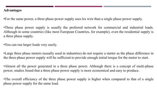
Advantages
•For the samepower, a three phase power supply uses les wire than a single phase power supply.
•Three phase power supply is usually the preferred network for commercial and industrial loads.
Although in some countries (like most European Countries, for example), even the residential supply is
a three phase supply.
•You can run larger loads very easily.
•Large three phase motors (usually used in industries) do not require a starter as the phase difference in
the three phase power supply will be sufficient to provide enough initial torque for the motor to start.
•Almost all the power generated in a three phase power. Although there is a concept of multi-phase
power, studies found that a three phase power supply is more economical and easy to produce.
•The overall efficiency of the three phase power supply is higher when compared to that of a single
phase power supply for the same load.
19.
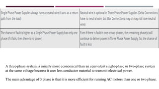
A three-phase systemis usually more economical than an equivalent single-phase or two-phase system
at the same voltage because it uses less conductor material to transmit electrical power.
The main advantage of 3 phase is that it is more efficient for running AC motors than one or two phase.
20.
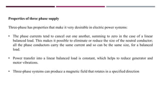
Properties of threephase supply
Three-phase has properties that make it very desirable in electric power systems:
• The phase currents tend to cancel out one another, summing to zero in the case of a linear
balanced load. This makes it possible to eliminate or reduce the size of the neutral conductor;
all the phase conductors carry the same current and so can be the same size, for a balanced
load.
• Power transfer into a linear balanced load is constant, which helps to reduce generator and
motor vibrations.
• Three-phase systems can produce a magnetic field that rotates in a specified direction
21.
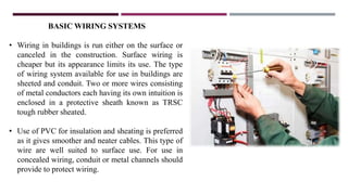
BASIC WIRING SYSTEMS
•Wiring in buildings is run either on the surface or
canceled in the construction. Surface wiring is
cheaper but its appearance limits its use. The type
of wiring system available for use in buildings are
sheeted and conduit. Two or more wires consisting
of metal conductors each having its own intuition is
enclosed in a protective sheath known as TRSC
tough rubber sheated.
• Use of PVC for insulation and sheating is preferred
as it gives smoother and neater cables. This type of
wire are well suited to surface use. For use in
concealed wiring, conduit or metal channels should
provide to protect wiring.
22.
TYPES OF ELECTRICALWIRING
There is wide choice of wiring; however one must keep in mind the safety of men & material.
The various types of wiring used are discussed below.
They are : -
•Cleat wiring.
•Batten wiring.
•Casing and caping.
•Conduit wiring.
23.
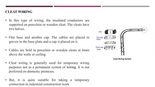
CLEAT WIRING
• Inthis type of wiring, the insulated conductors are
supported on porcelain or wooden cleat. The cleats have
two halves.
• One base and another cap. The cables are placed in
groves in the base plate and a cap is placed on it.
• Cables are held in porcelain or wooden cleats at 6mm
above the walls or ceiling.
• Cleat wiring is generally used for temporary wiring
purposes not as a permanent system of wiring. It is not
preferred on domestic premises.
• But, it is quite suitable for taking a temporary
connection in industrial construction work.
24.
Advantages
•This fitting isvery easy and cheap.
•This method was very good for temporary fitting where some kind of construction is
going on.
Disadvantages
•This fitting doesn’t look good.
•As the cable is kept out, so it has the effect of every kind of environment, a low-quality
wire spoils quickly.
25.
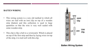
BATTEN WIRING
• Thiswiring system is a very old method in which all
wires are tied with an iron clip on top of a wooden
strip (batten) and this collection is used in large
quantities so that the wire is very well sealed with
some wooden strip.
• This clip is like a belt to a wristwatch. Which is placed
on top of the first strip and then by laying wires on top
of the strip, it is tied well with this clip.
26.
Advantages
•Wiring is simpleand easy to do
•This wiring method is cheaper than another wiring
•This wiring also looks great.
•It is also easy to repair this wiring
Disadvantages
•We can not do this wiring in the open outside the house
•This wiring is not protected from the external environment because it has a great impact on the
weather.
•The heavy wire cannot be used in this wiring
•This wiring is up to 220 V only.
•Require more cables and wires.
•Cable sag may take place after a long period.
27.
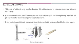
CASING AND CAPPING
•This type of wiring is very popular. Because this wiring system is very easy to do and it is also
very cheap.
• If it is done above the walls, then anyone can fit it very easily in this wiring fitting, the wires are
placed inside the plastic casing or wooden enclosures.
• It is a kind of open fitting it is covered from the top so that it looks good and looks more secure.
28.
Advantages
•This wiring systemis much easier and cheaper than other wiring systems.
•This wiring system is very strong and long-lasting.
•One can make changes to this wiring very easily.
•There is no risk of electric shock as it covers the wires well.
•If phase and neutral follow a different path, repair becomes easy.
Disadvantages
•If there is a fire in the wires inside it, then this whole fitting can burn.
29.
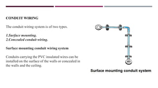
CONDUIT WIRING
The conduitwiring system is of two types.
1.Surface mounting.
2.Concealed conduit wiring.
Surface mounting conduit wiring system
Conduits carrying the PVC insulated wires can be
installed on the surface of the walls or concealed in
the walls and the ceiling.
30.
Concealed conduit wiring
•Conduit wiring is a system, basically, wires or cables which are routed in metal or plastic
inside the wall.
• Conduits isolate wires to avoid exposure, thereby reducing the risk of fires, short circuits,
fire, electrocution.
• Modern practice is the hidden installation of the conduit in the plaster of the wall, so that
appearance of the house or the building remains unaffected. Conduits are available in
standard lengths.
• The conduits system for each circuit must be erected completely before any cable is drawn
in.
31.
Advantages
•A conduit wiringsystem is best for domestic and commercial installations.
•It provides proper protection to the installation against shock, fire hazards mechanical damage.
•Protected from external damage due to rodents, short circuit.
•Conduit is durable and strong, can last for a long time.
•Great protection as it is more robust.
Disadvantages
•If cable got damaged. replacement of cable is difficult compared to any other.
•Requires skill in running the conduit and wires through it.
•The cost, time, and efforts of installation are high.
32.
ELECTRICALAPPLIANCES
• There aremany ways in which electricity can be used to save labour in the home. A vast
number of appliances are designed to run on the ordinary domestic supply.
• The three basic application of electricity are – the production of heat, light and power and in
many devices they are used in combination.
• Electronic appliances such as radio and television sets, and record players constitute a fourth
class and telephone a fifth.
• All the electrical appliances requiring a current of more than 5 A should be fitted with an earth
or ground wire to safe guard the user against shocks from leakages of current.
• Their supply cables thus carry three-pin plugs, and in the best type of socket no current can
flow until the earth-pin can be made its contact.
33.
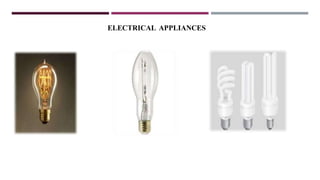
ELECTRICALAPPLIANCES
• There arefour main ways in which electricity can be converted into lights
• It can flow through a wire, so that it glows(lamps), modern filament lamps use coil of tungsten
wire which gives a much whiter light than carbon, and the bulb contains nitrogen and argon.
• Most household bulbs are 25 to 150 watt of electric power, but some large tungsten lamps used in
search lights an in television studios use as much as 30 kw.
• Discharge lamps are long tubes containing a gas or vapour. When electricity passes through a
pure gas at low pressure, energy is transferred to the gas atoms, causing them to emit radiations.
• The wavelength of this radiation, which determines color, depends on the gas e.g., sodium vapor
and neon emit visible radiation.
• Sodium produces an efficient yellow light, mercury produces a bluish white light and some ultra-
violet radiations, and neon gives off a strong red light.
ELECTRIC INSTALLATIONS
Electric Installationsrequire necessary design, planning taking into consideration the whole
requirement of the activities to be carried out in the building.
The following steps are suggested for the same..
• Planning & Designing
• Layout of working drawings
• Application to electric supply company for granting estimated low supply and requirement of sub-
stations/ transformers
• Laying conduit for underground supply lines before concreting and completing the plinth work.
• Laying conduits in slabs and beam reinforcement, fixing of fan hooks/ boxes in slabs reinforcement
for main supply to consumer units/ rooms
36.
ELECTRIC INSTALLATIONS
• Physicalmarking of layout of wiring in all units/ rooms.
• Providing & laying complete wiring
• Fixing all fittings and fixtures and complete electrical installations
• Testing of Installations
• Providing consumer meters.
• Submission of test reports to electric supply company for supply connection after obtaining NOC
from PWD in cases of building exceeds 15m height.
• Checking of electrical installation by authorized officer of electrical supply company before
passing & sealing of meters.
• Permanent electric supply connection to buildings and consumer thereof.
37.
ELECTRIC INSTALLATIONS
Design &Planning
• The design and planning of an electrical Installation is governed by the type of user of the
building and requirement of the consumer thereof. Therefore it is essential to consult
competent electrical engineer/ licensed electrical contractor at the planning stage for
providing and planning electrical installations, which should be safe and efficient in its use
and adequate for its intended purpose.
• For designing layout of electrical installations for specific requirement of power use it is
essential at planning stage that the architect in consultation with structural engineer,
electrical engineer and owner/developer to decide about following
38.
ELECTRIC INSTALLATIONS
• Neededaccommodation for making provision of sub-station, meter room, switch room, services
cable duct, rising mains and cables, opening and chases required in floors and walls for
intending electrical installations.
• Total load requirement i.e. lights, fans, power etc.
• Anticipated future increase in power consumption. Requirement of electric supply company
including location and distance of main supply connection point.
• Layout of wiring installation, whether open conduit or concealed
• After collecting necessary information and suggestions from other consultants the architect
should prepare detailed working drawing of complete electrical installation in consultation with
licensed electrical contractor
39.
EXECUTION
• The executionof entire electrical Installation should be carried out under the guidance and supervision of
competent electrical engineer/through licensed electrical contractor; in accordance to the design and
specification provided in the tender and strictly as per rules and regulations of electrical supply.
• The electrical contractor should decide his sequence of work in consultation with the architect in such a
manner that it will not affect/conflict with working of other agencies and it will allow other service
agencies to work smoothly and simultaneously without any interruption.
• The electrical contractor should get approval for all materials including fitting and fixtures to be used from
the architect before commencement of work.
• The contractor should arrange temporary electrical supply for construction purpose; before proper work is
commenced. • At the end of work the electrical contractor should check and test the entire electrical
installation work and get it approved from the electrical supply company.
• The electrical contractor should submit his test report and completion certificate in required forms for
consumer meter and permanent electric supply connections to the buildings.
40.
STAIRCASE & CORRIDORLIGHTING
• The following provisions have been recommended under the development control regulations.
• The staircase and corridor lighting should be on separate circuit and should be independently
connected so that they could be operated by one switch installations.
• Stair case and corridor lighting should also be connected to alternate supply as defined in sub
regulation.
• Emergency lights should be provided in the staircase/Corridor for multi-storied special buildings.
41.
Distribution Board
A distributionboard (also known as panel-board or breaker panel) is a component of an electricity
supply system which divides an electrical power feed into subsidiary circuits, while providing a
protective fuse or circuit breaker for each circuit in a common enclosure
Transformers
A transformer can accept energy at one voltage and deliver it at another voltage. This permits electrical
energy to be generated at relatively low voltages and transmitted at high voltages and low currents, thus
reducing line losses and voltage drop
Main Distribution Board
The main distribution board (MDB) is an essential component of an electrical power distribution
system, and typically includes the following components: Main circuit-breaker. The main circuit-
breaker is the first device that power from the utility or generator passes through on its way to the rest of
the building.
42.
What is electricalplan in interior design?
The electrical plan is sometimes called as electrical drawing or wiring diagram. It is a type of technical
drawing that delivers visual representation and describes circuits and electrical systems. It consists of
electrical symbols and lines that showcase the engineer's electrical design to its clients.
An electrical drawing may include all of these essential details described below:
•Interconnection of electrical wires and other parts of the system
•Connection of different components and fixtures to the system
•Power lines with details such as size, voltage, rating, and capacity
•Power transformers and also their winding connections
•The main switches, tiebreaker, and fused switches
•Other essential equipment such as solar panels, batteries, generators, air conditioning, and so on.
43.
How to Draftan Electrical Plan?
An excellent electric plan significantly adds aesthetics and comfort in a building. Your drawing
must include types of fixtures, locations, cables, switches, and hardwired appliances. However, an
electrical plan may look scary and complicated, but they are not. These are pointers you should
remember while drafting an electric plan.
Step 1: Know Your Layout
Either use a software or a graph paper and make a scale drawing of the different rooms. Make sure
to include features such as cabinets, counters, stoves, beds, and other various symbols.
Step 2: Plan it in Advance
After finalizing your layout, focus on your electrical plan. The wirings go through the ceilings,
walls, and floor before they are plastered, laid out, and fixed.
44.
Step 3: UseInterior Layout as Your Starting Point
Around your exits and entries, place your fan, AC switches, and light. Now, place your electrical
outlets near the counters and tables. Then, decide where to put your big appliances like TV,
computer, washing machine, printer, etc.
When making an electrical plan, ask yourself some questions:
Do I place switches at a convenient location?
Is the electrical load on all the circuit alright?
Do I place enough easy-to-reach receptacles?
Step 4: Walk Through Your Plan
Once you are finished with your layout, print it out, and walk through your home while holding it.
Since there are no walls and electricity, the arrangement can be easily changed; therefore, imagine
that you are turning on and plugging in appliances. This will enable you to put switches and outlets
in the best places.
45.
Tips for MakingElectrical Plans
Here are a few tip-offs you should consider while making an electric plan.
1. Think About Furniture Placement
Planning about how you are going to set your furniture is essential because you will have an idea
where you are going to place your light switches and electrical outlets. Most people make this
mistake, and they end up placing them at awkward places.
2. Plan for Additional Outlets
Renovating can drain a considerable amount of money. Let's say you want to purchase side table
lamps, kitchen ceiling lights, etc. You may not buy this now, but maybe after a few months or a
year later. Having these additional electrical outlets will save you from a lot of mess. Thereby, it is
crucial to plan for other appliances now.
46.
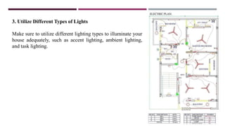
3. Utilize DifferentTypes of Lights
Make sure to utilize different lighting types to illuminate your
house adequately, such as accent lighting, ambient lighting,
and task lighting.
47.
The Electric Act2003
• The salient features of this act
• The central Govt to prepare a National Electricity Policy in Consultation with State Govt.+
• Thrust to complete the rural electrification and provide for management of rural distribution by
Panchayats, Cooperative Societies, non-government organizations, franchises etc.
• Provision for license free generation and distribution in the rural areas.
• Provision for private licenses in transmission and entry in distribution through an independent network.
• The state Electricity Regulatory Commission is a mandatory requirement.
• Metering of all electricity supplied made mandatory.
• Provisions relating to theft of electricity made more stringent.
• Provisions safeguarding consumer interests


![74676371-Coagulation-and-Flocculation[1].ppt](https://cdn.slidesharecdn.com/ss_thumbnails/74676371-coagulation-and-flocculation1-260116154109-a3cbf55e-thumbnail.jpg?width=640&height=640&fit=bounds)


