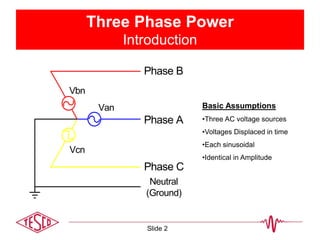
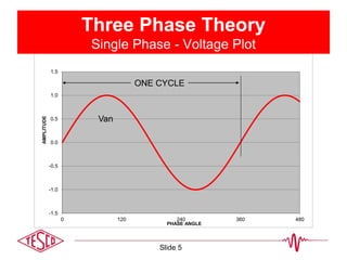
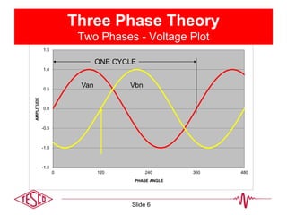
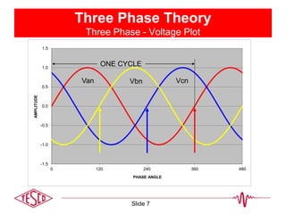
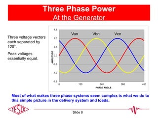
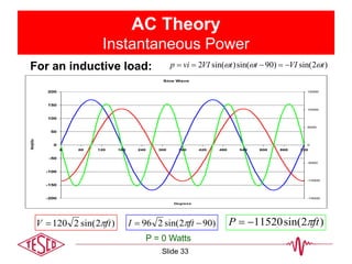
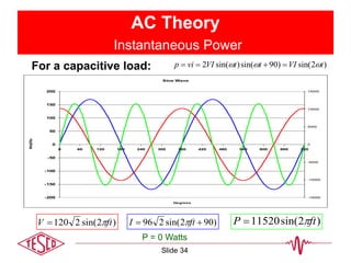
1) The document discusses three-phase power theory, including basic assumptions about three AC voltage sources displaced 120 degrees in time.
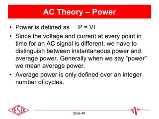
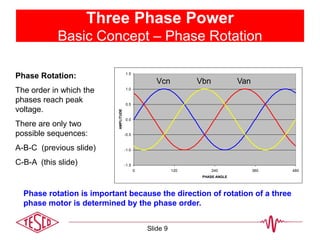
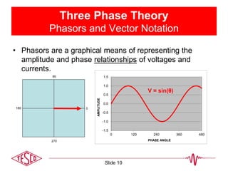
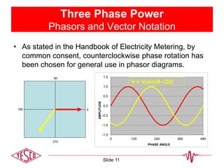
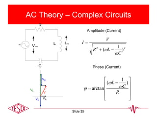
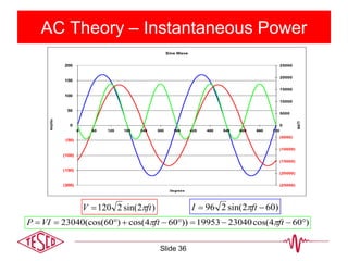
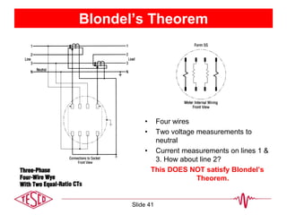
2) Key concepts covered include phasors, phase rotation, resistive/inductive/capacitive loads, instantaneous and average power, and Blondel's theorem for measuring power in a multi-wire system.
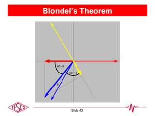
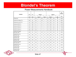
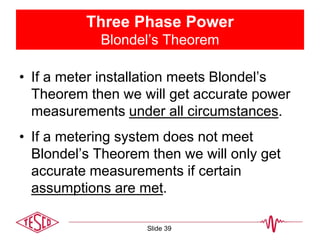
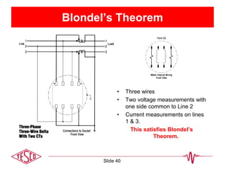
3) Blondel's theorem states that the total power in an N-wire system can be determined from the readings of N-1 wattmeters.
2. Three Phase Power
Introduction
Basic Assumptions
•Three AC voltage sources
•Voltages Displaced in time
•Each sinusoidal
•Identical in Amplitude
Van
Vcn
Vbn
Phase A
Phase B
Phase C
Neutral
(Ground)
Slide 2
3. AC Theory – Sine Wave
)2sin( ftVV pk
0
)2sin(2 ftVV rms
120rmsV
169pkV
Slide 3
8. -1.5
-1.0
-0.5
0.0
0.5
1.0
1.5
0 120 240 360 480
AMPLITUDE
PHASE ANGLE
Three Phase Power
At the Generator
Three voltage vectors
each separated by
120°.
Peak voltages
essentially equal.
Most of what makes three phase systems seem complex is what we do to
this simple picture in the delivery system and loads.
VcnVan Vbn
Slide 8
9. Three Phase Power
Basic Concept – Phase Rotation
-1.5
-1.0
-0.5
0.0
0.5
1.0
1.5
0 120 240 360 480
PHASE ANGLE
AMPLITUDE
VanVbnVcn
Phase Rotation:
The order in which the
phases reach peak
voltage.
There are only two
possible sequences:
A-B-C (previous slide)
C-B-A (this slide)
Phase rotation is important because the direction of rotation of a three
phase motor is determined by the phase order.
Slide 9
10. -1.5
-1.0
-0.5
0.0
0.5
1.0
1.5
0 120 240 360 480
AMPLITUDE
PHASE ANGLE
0
270
90
180
Three Phase Theory
Phasors and Vector Notation
• Phasors are a graphical means of representing the
amplitude and phase relationships of voltages and
currents.
V = sin(θ)
Slide 10
11. 0
270
90
180
Three Phase Power
Phasors and Vector Notation
• As stated in the Handbook of Electricity Metering, by
common consent, counterclockwise phase rotation has
been chosen for general use in phasor diagrams.
-1.5
-1.0
-0.5
0.0
0.5
1.0
1.5
0 120 240 360 480
AMPLITUDE
PHASE ANGLE
V = V0sin(θ-120)
Slide 11
12. 0
270
90
180
Three Phase Power
Phasors and Vector Notation
• The phasor diagram for a simple 3-phase system has
three voltage phasors equally spaced at 120° intervals.
• Going clockwise the order is A – B – C.
-1.5
-1.0
-0.5
0.0
0.5
1.0
1.5
0 120 240 360 480
AMPLITUDE
PHASE ANGLE
V = V0sin(θ-240)
Slide 12
13. Three Phase Theory
Symbols and Conventions
• Systems formed by
interconnecting secondary
of 3 single phase
transformers.
• Generally primaries are not
show unless details of
actual transformer are
being discussed.
A
B
C
N
Ia
Ib
Ic
Slide 13
14. Three Phase Theory
Symbols and Conventions
• Often even the coils are
not shown but are
replaced by simple line
drawings
A
B
C
N
Ia
Ib
Ic
Slide 14
15. 3 Phase, 4-Wire “Y” Service
0° = Unity Power Factor
• Three
Voltage
Phasors
• 120° Apart
• Three
Current
Phasors
• Aligned with
Voltage at
PF=1
Slide 15
16. Symbols and Conventions
Labeling
• Voltages are generally labeled Va, Vb, Vc, Vn for the
three phases and neutral
• This can be confusing in complex cases.
• The recommended approach is to use two subscripts so
the two points between which the voltage is measured
are unambiguous.
B
C
A
N Vca
Vbn
Van
Vcn
Vab
Vbc
Vab means voltage at “a” as
measured relative to “b”.
Slide 16
17. 2 Phase, 3-Wire “Y” Service
“Network Connection”
Single phase variant of the service.
Two voltage sources with their returns connected to a common point.
Provides 208 rather than 240 volts across “high side” wires.
B
C
N
A
208
120
120
Source
B
C
N
Ia
Ib
Load
A
Slide 17
18. 2 Phase, 3-Wire “Network” Service
• Two Voltage
Phasors
• 120° Apart
• Two Current
Phasors
• Aligned with
Voltage at
PF=1
Slide 18
19. 3 Phase, 3-Wire Delta Service
Common service type for industrial customers. This service may have
NO neutral.
•Voltages normally measured relative to phase B.
•Sometimes phase B will be grounded
•Voltage and current vectors do not align.
•Service is provided even when a phase is grounded.
Source
B
C
Ia
Ib
Ic
Load
A
B
C
A
240
240
240
Slide 19
20. 3 Phase, 3-Wire Delta Service
Resistive Loads
• Two Voltage
Phasors
• 60° Apart
• Two Current
Phasors
• For a resistive
load one
current leads by
30° while the
other lags by
30°
Slide 20
21. 3 Phase, 3-Wire Delta Service
Understanding the Diagram
Vab
Vca
B A
C
Vbc
VabB A
C
Vcb
Source
B
C
Ia
Ib
Ic
Load
A
Slide 21
22. 3 Phase, 3-Wire Delta Service
Understanding the Diagram
Ia
Iac
Iab
Icb
Ic
Ica
Source
B
C
Ia
Ib
Ic
Load
A
Slide 22
23. 3 Phase, 3-Wire Delta Service
Resistive Load
• Two Voltage
Phasors
• 60° Apart
• Two Current
Phasors
• For a resistive
load one
current leads
by 30° while
the other lags
by 30°
Slide 23
24. 3 Phase, 4-Wire Delta Service
Common service type for industrial customers. Provides a residential
like 120/240 service (lighting service) single phase 208 (high side) and
even 3 phase 240 V.
•Voltage phasors form a “T” 90° apart
•Currents are at 120° spacing
•In 120/120/208 form only the “hot” (208) leg has its voltage and
current vectors aligned.
Source
B
C
Ib
Ic
Load
IaA
N
Slide 24
25. 3 Phase, 4-Wire Delta Service
Resistive Load
• Three
Voltage
Phasors
• 90° Apart
• Three
Current
Phasors
• 120° apart
Slide 25
26. AC Theory – Resistive Load
Sine Wave
-200
-150
-100
-50
0
50
100
150
200
0 60 120 180 240 300 360 420 480 540 600 660 720
Degrees
Amplitude
AC
RVrms
Irms
Resistors are measured in Ohms. When an AC voltage is applied to a resistor, the
current is in phase. A resistive load is considered a “linear” load because when the
voltage is sinusoidal the current is also sinusoidal.
Slide 26
27. AC Theory – Inductive Load
Sine Wave
-200
-150
-100
-50
0
50
100
150
200
0 60 120 180 240 300 360 420 480 540 600 660 720
Degrees
Amplitude
Inductors are measured in Henries. When an AC voltage is applied to an inductor,
the current is 90 degrees out of phase. We say the current “lags” the voltage. A
inductive load is considered a “linear” load because when the voltage is sinusoidal
the current is also sinusoidal.
AC
LVrms
Irms
Slide 27
28. AC Theory – Capacitive Load
AC CVrms
Irms
Capacitors are measured in Farads. When an AC voltage is applied to a capacitor,
the current is 90 degrees out of phase. We say the current “leads” the voltage. A
capacitive load is considered a “linear” load because when the voltage is
sinusoidal the current is sinusoidal.
Sine Wave
-200
-150
-100
-50
0
50
100
150
200
0 60 120 180 240 300 360 420 480 540 600 660 720
Degrees
Amplitude
Slide 28
29. AC Theory – Power
• Power is defined as P = VI
• Since the voltage and current at every point in
time for an AC signal is different, we have to
distinguish between instantaneous power and
average power. Generally when we say “power”
we mean average power.
• Average power is only defined over an integral
number of cycles.
Slide 29
30. Time Out for Trig
(Right Triangles)
c
a
)cos(
a
b
)tan(
The Right Triangle:
The Pythagorean theory
c2 = a2 + b2
c
b
)sin(
a
c
b
9 0 °
Slide 30
31. AC Theory – Power Triangle
(Sinusoidal Waveforms)
If V = sin(ωt) and I = sin(ωt - θ) (the load is linear)
then
Active Power = VIcos(θ) Watts
Reactive Power = VIsin(θ) VARs
Apparent Power = VI VA
Power Factor = Active/Apparent = cos(θ)
Watts
VARs
Slide 31
32. AC Theory
Instantaneous Power
)2sin(2120 ftV )2sin(296 ftI )2(sin23040 2
ftP
Sine Wave
(200)
(150)
(100)
(50)
0
50
100
150
200
0 60 120 180 240 300 360 420 480 540 600 660 720
Degrees
Amplitude
(25000)
(20000)
(15000)
(10000)
(5000)
0
5000
10000
15000
20000
25000
WATTS
For a resistive load: ))2cos(1()(sin2 2
tVItVIvip
P = 11520 Watts
Slide 32
33. AC Theory
Instantaneous Power
)2sin(2120 ftV )902sin(296 ftI )2sin(11520 ftP
For an inductive load:
P = 0 Watts
)2sin()90sin()sin(2 tVIttVIvip
Sine Wave
-200
-150
-100
-50
0
50
100
150
200
0 60 120 180 240 300 360 420 480 540 600 660 720
Degrees
Amplitude
-15000
-10000
-5000
0
5000
10000
15000
Slide 33
34. AC Theory
Instantaneous Power
)2sin(2120 ftV )902sin(296 ftI )2sin(11520 ftP
For a capacitive load:
P = 0 Watts
)2sin()90sin()sin(2 tVIttVIvip
Sine Wave
-200
-150
-100
-50
0
50
100
150
200
0 60 120 180 240 300 360 420 480 540 600 660 720
Degrees
Amplitude
-15000
-10000
-5000
0
5000
10000
15000
Slide 34
35. AC Theory – Complex Circuits
AC
C
Vrms
Irms
R
L
22
)
1
(
C
LR
V
I
Amplitude (Current)
R
C
L )
1
(
arctan
Phase (Current)
VC
V
VL
VC
VR
Slide 35
37. Three Phase Power
Blondel’s Theorem
If energy be supplied to any system of conductors
through N wires, the total power in the system is
given by the algebraic sum of the readings of N
wattmeters, so arranged that each of the N wires
contains one current coil, the corresponding voltage
coil being connected between that wire and some
common point. If this common point is on one of the
N wires, the measurement may be made by the use
of N-1 wattmeters.
Slide 37
38. Three Phase Power
Blondel’s Theorem
• Simply – We can measure the power in a
N wire system by measuring the power in
N-1 conductors.
• For example, in a 4-wire, 3-phase system
we need to measure the power in 3
circuits.
Slide 38
39. Three Phase Power
Blondel’s Theorem
• If a meter installation meets Blondel’s
Theorem then we will get accurate power
measurements under all circumstances.
• If a metering system does not meet
Blondel’s Theorem then we will only get
accurate measurements if certain
assumptions are met.
Slide 39
40. Blondel’s Theorem
• Three wires
• Two voltage measurements with
one side common to Line 2
• Current measurements on lines
1 & 3.
This satisfies Blondel’s
Theorem.
Slide 40
41. Blondel’s Theorem
• Four wires
• Two voltage measurements to
neutral
• Current measurements on lines 1 &
3. How about line 2?
This DOES NOT satisfy Blondel’s
Theorem.
Slide 41
42. Blondel’s Theorem
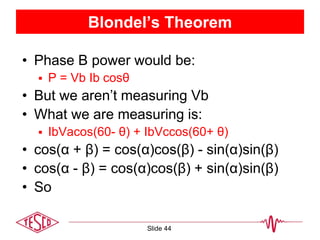
• In the previous example:
What are the “ASSUMPTIONS”?
When do we get errors?
• What would the “Right Answer” be?
• What did we measure?
Slide 42
)cos()cos()cos( cccbbbaaasys IVIVIVP
)]cos()cos([)]cos()cos([ bbcccbbaaasys IIVIIVP
44. Blondel’s Theorem
• Phase B power would be:
P = Vb Ib cosθ
• But we aren’t measuring Vb
• What we are measuring is:
IbVacos(60- θ) + IbVccos(60+ θ)
• cos(α + β) = cos(α)cos(β) - sin(α)sin(β)
• cos(α - β) = cos(α)cos(β) + sin(α)sin(β)
• So
Slide 44
46. Blondel’s Theorem
• If Va ≠ Vb ≠ Vc then the error is
• %Error =
-Ib{(Va+Vc)/(2Vb) - (Va-Vc) 0.866sin(θ)/(Vbcos(θ))
How big is this in reality? If
Va=117, Vb=120, Vc=119, PF=1 then E=-1.67%
Va=117, Vb=116, Vc=119, PF=.866 then E=-1.67%
Slide 46
48. AC Theory – Power
• Power is defined as P = VI
• Since the voltage and current at every point in
time for an AC signal is different, we have to
distinguish between instantaneous power and
average power. Generally when we say “power”
we mean average power.
• Average power is only defined over an integer
number of cycles.
Slide 48
49. Harmonics
Curse of the Modern World
• Every thing discussed so far was based on
“Linear” loads.
For linear loads the current is always a simple
sine wave. Everything we have discussed is
true.
• For nearly a century after AC power was in
use ALL loads were linear.
• Today, many loads are NON-LINEAR.
Slide 49
50. Harmonic Load Waveform
Six Pole Motor
-250
-200
-150
-100
-50
0
50
100
150
200
250
0 60 120 180 240 300 360
-45000
-35000
-25000
-15000
-5000
5000
15000
25000
35000
Pa Voltage
Pa Current
Pa Power
Pa VAR
Eq.# Quantity Phase A
1 V(rms) (Direct Sum) 100
2 I(rms) (Direct Sum) 108
3 V(rms) (Fourier) 100
4 I(rms) (Fourier) 108
5 Pa = (∫ V(t)I(t)dt) 10000
6 Pb = ½∑VnIncos(θ) 10000
7 Q = ½∑VnInsin(θ) 0.000
8 Sa = Sqrt(P^2 +Q^2) 10000
9 Sb = Vrms*Irms(DS) 10833
10 Sc = Vrms*Irms(F) 10833
13 PF = Pa/Sa 1.000
14 PF = Pb/Sb 0.923
15 PF = Pb/Sc 0.923
V = 100Sin(ωt) I = 100Sin(ωt) + 42Sin(5 ωt)
Slide 50
51. Harmonic Load Waveform
Eq.# Quantity Phase A
1 V(rms) (Direct Sum) 100
2 I(rms) (Direct Sum) 108
3 V(rms) (Fourier) 100
4 I(rms) (Fourier) 108
5 Pa = (∫ V(t)I(t)dt) 10000
6 Pb = ½∑VnIncos(θ) 10000
7 Q = ½∑VnInsin(θ) 0.000
8 Sa = Sqrt(P^2 +Q^2) 10000
9 Sb = Vrms*Irms(DS) 10833
10 Sc = Vrms*Irms(F) 10833
13 PF = Pa/Sa 1.000
14 PF = Pb/Sb 0.923
15 PF = Pb/Sc 0.923
• Important things to note:
Because the voltage is NOT
distorted, the harmonic in the
current does not contribute to
active power.
It does contribute to the
Apparent power.
Does the Power Triangle hold
There is considerable
disagreement about the
definition of various power
quantities when harmonics are
present.
V = 100Sin(ωt) I = 100Sin(ωt) + 42Sin(5 ωt)
22
? QPS
Slide 51
52. 3 Phase Power Measurement
• We have discussed how to measure and
view power quantities (W, VARs, VA) in a
single phase case.
• How do we combine them in a multi-phase
system?
• Two common approaches:
Arithmetic
Vectorial
Slide 52
53. 3 Phase Power Measurement
SA
SVPa
Pb
Pc
Sa
Sb
Sc
Qa
Qb
Qc
SV
Slide 53
54. 3 Phase Power Measurement
• VAR and VA calculations can lead to some
strange results:
If we define
PH W Q VA
A 100 0 100
B 120 55 132
C 120 -55 132
Arithmetic VA 364
Vector VA 340 Arithmetic VA VS I
Vector VA SPQ
22
)()( CBACBA QQQWWWVA
Slide 54
55. Questions and Discussion
Bill Hardy
TESCO – The Eastern Specialty Company
Bristol, PA
215-688-0298 (cell)
215-785-2338
This presentation can also be found under Meter
Conferences and Schools on the TESCO website:
www.tesco-advent.com
Slide 55