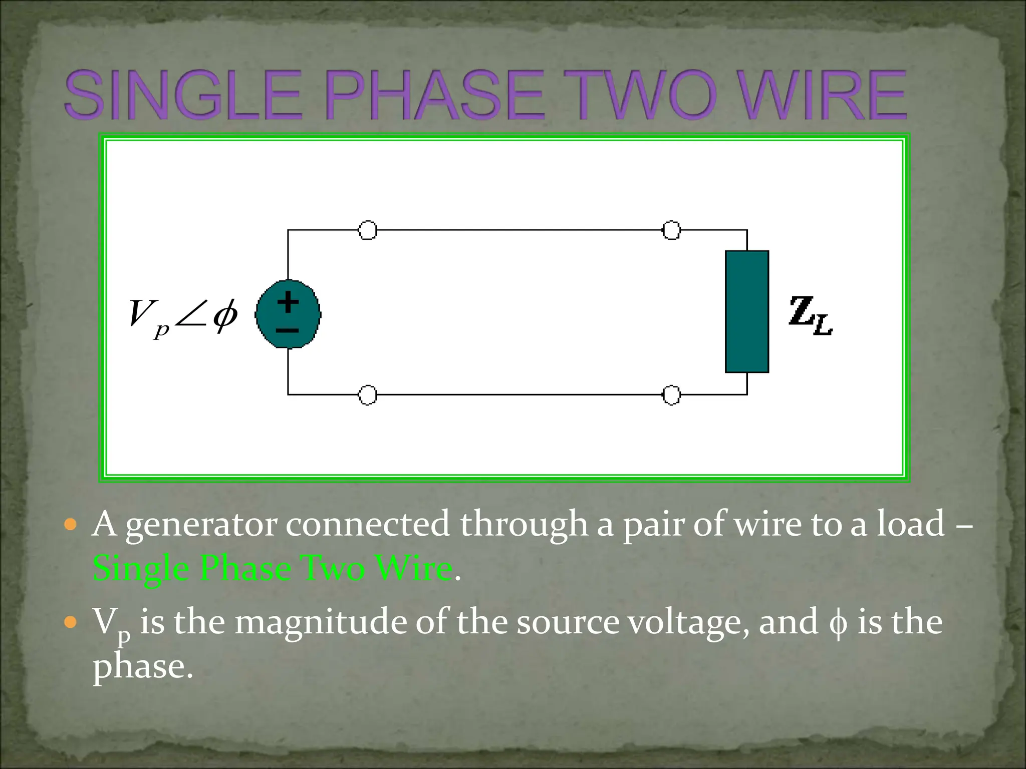
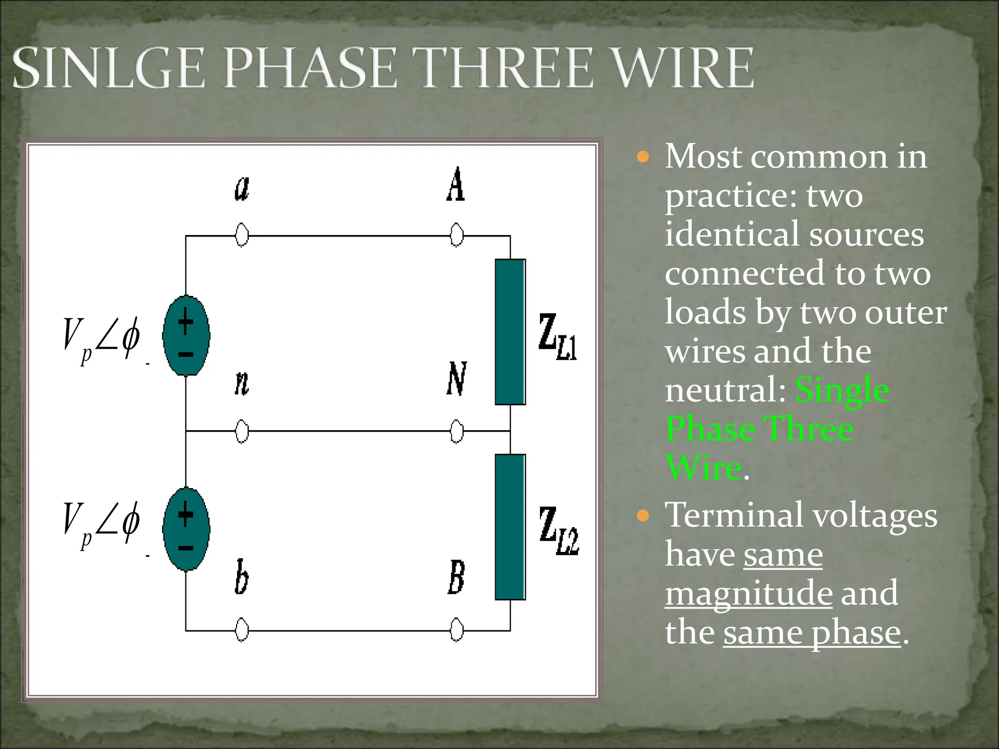
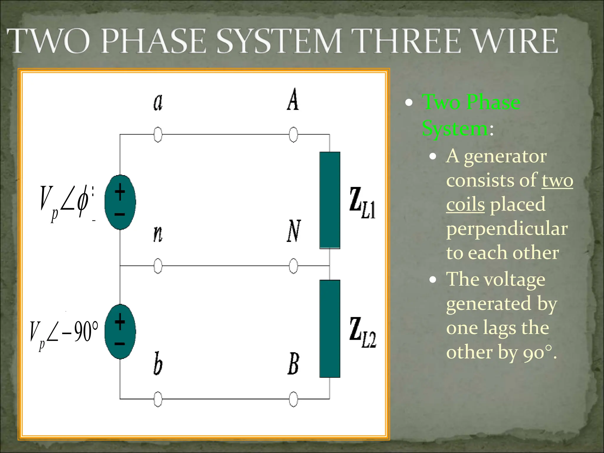
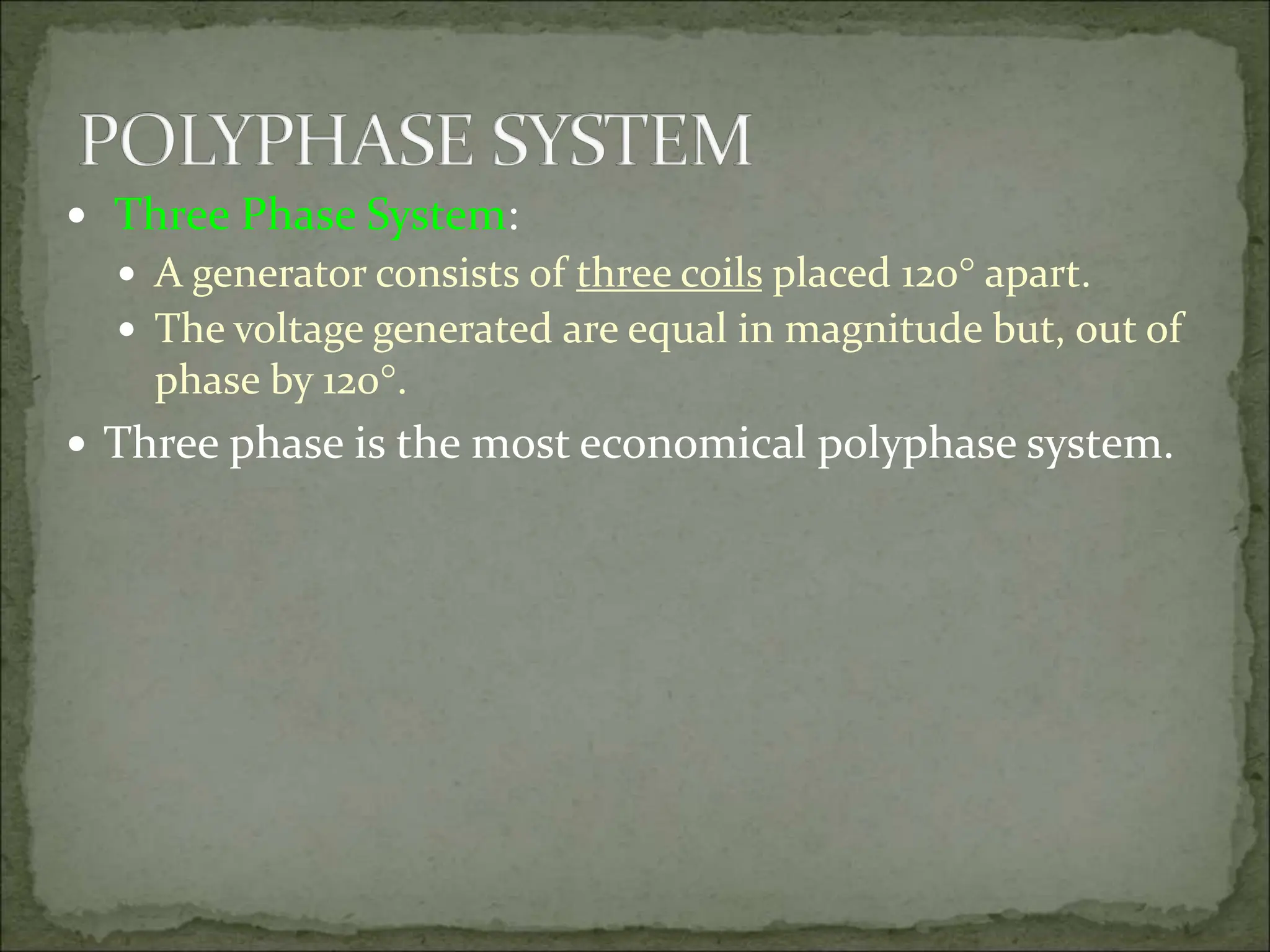
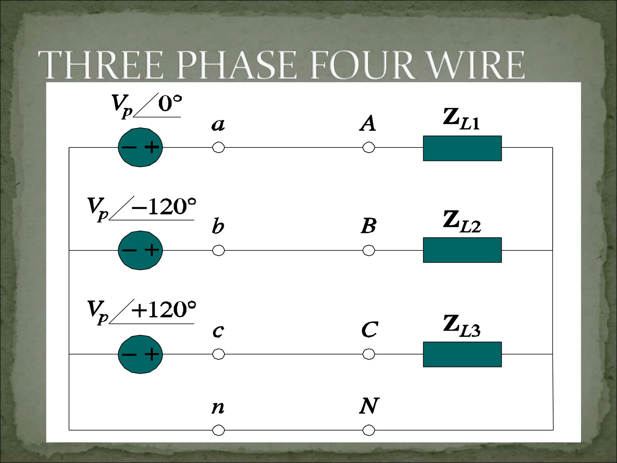
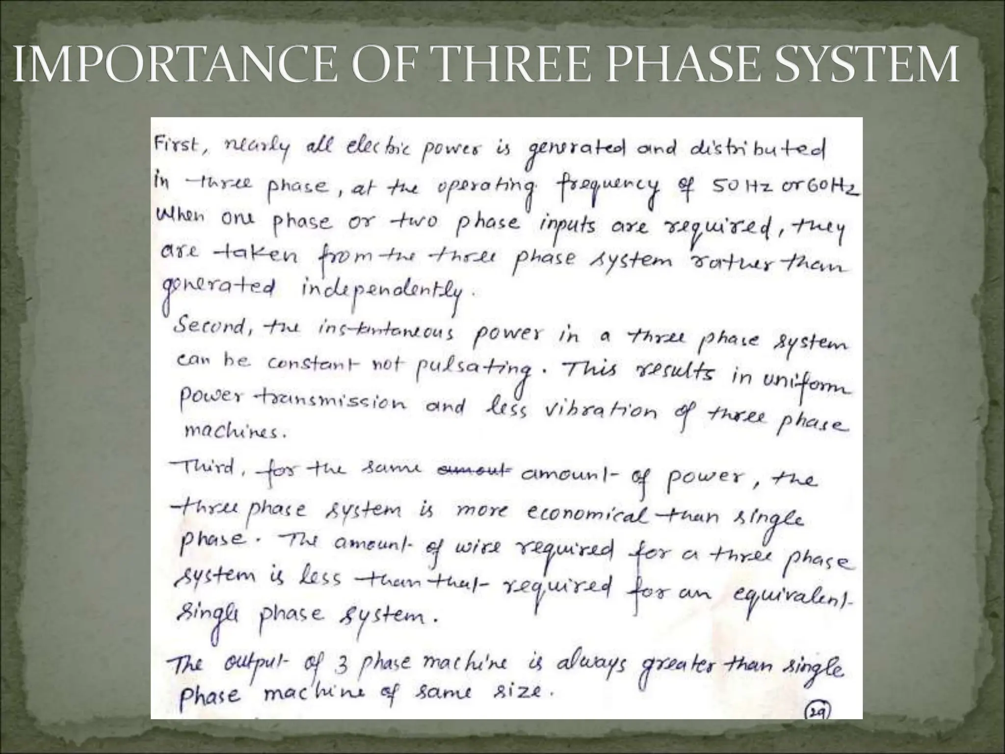
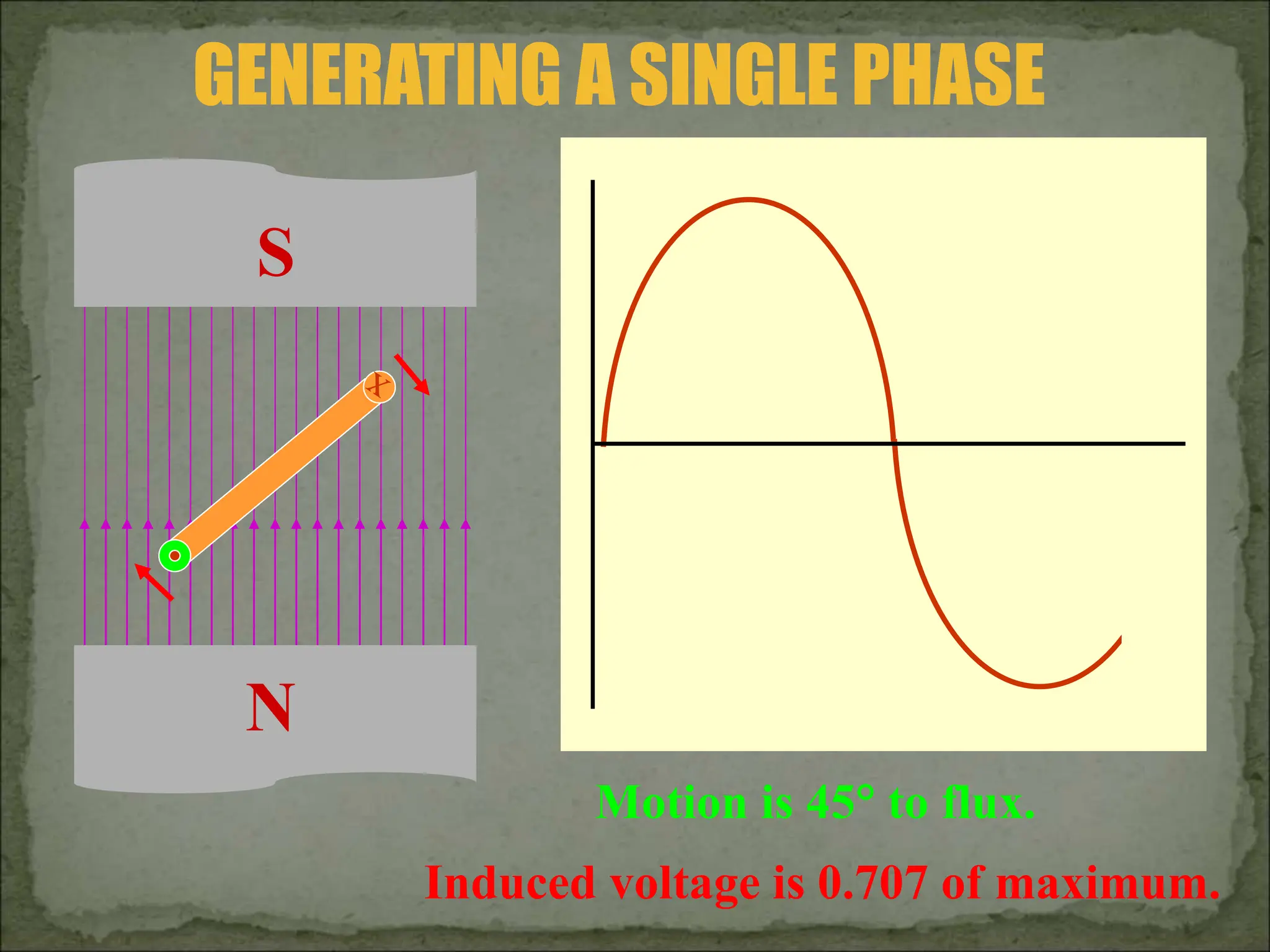
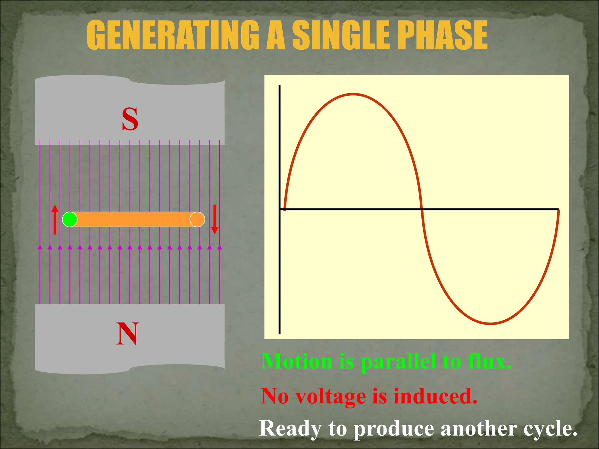
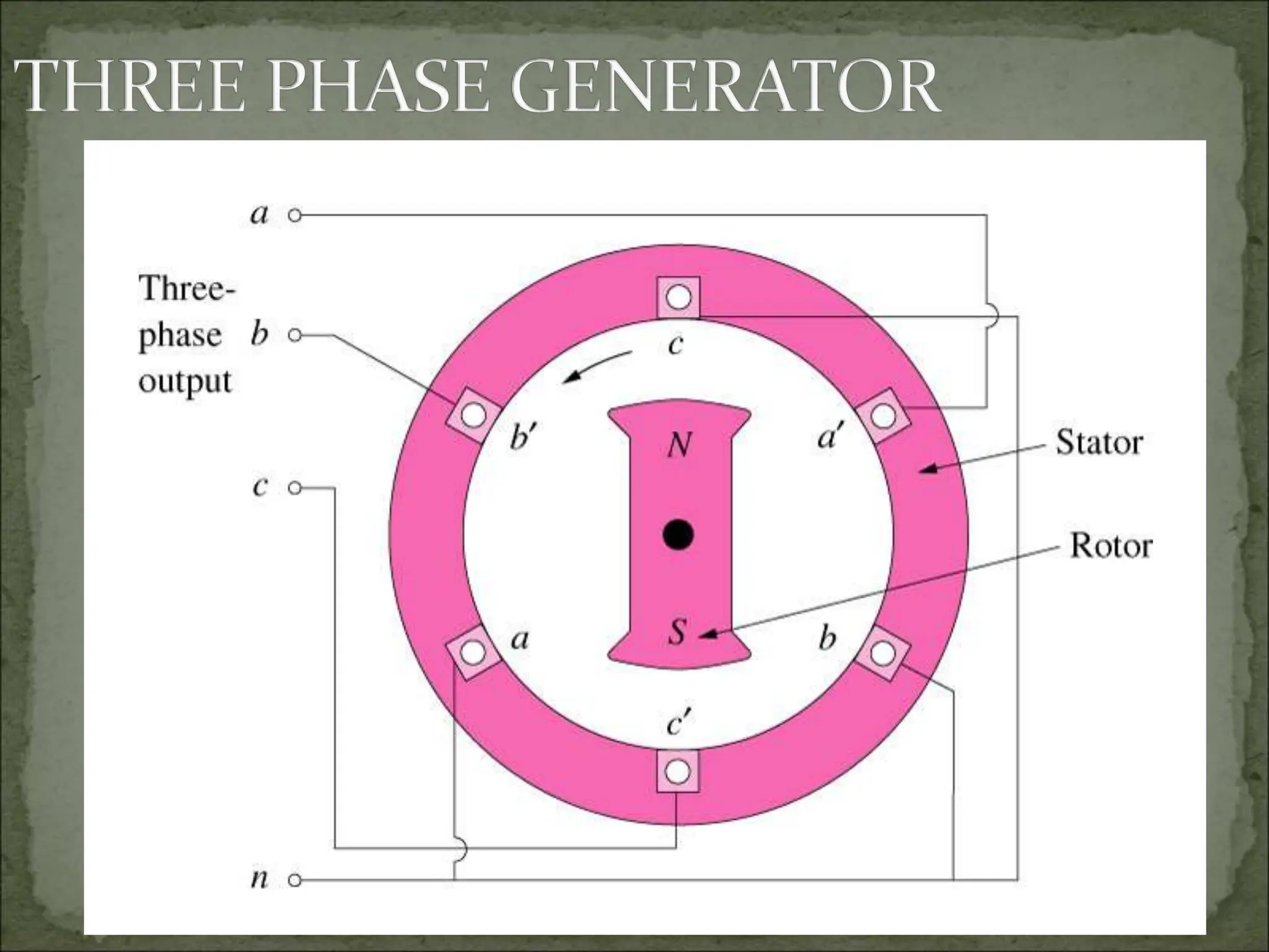
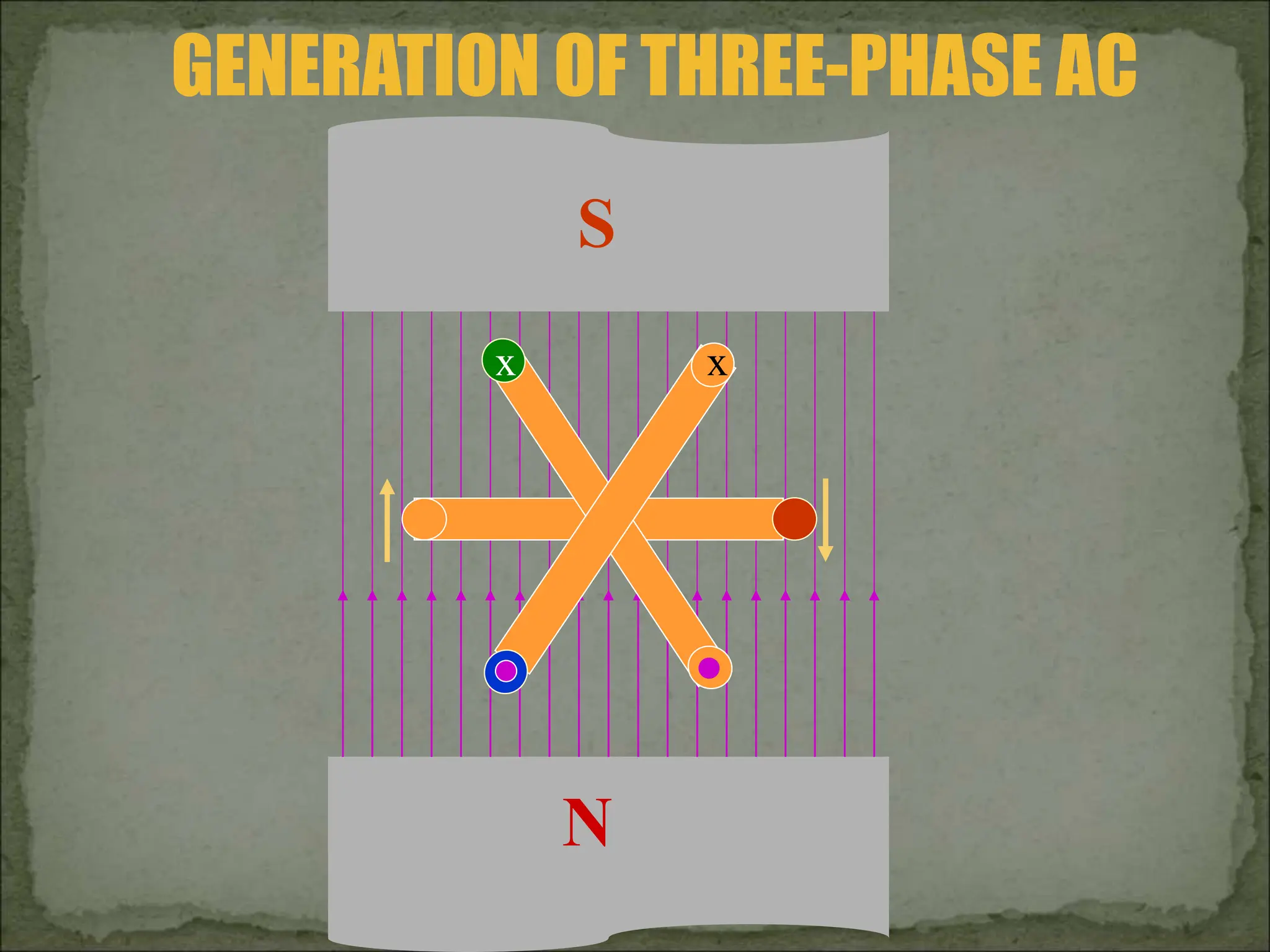
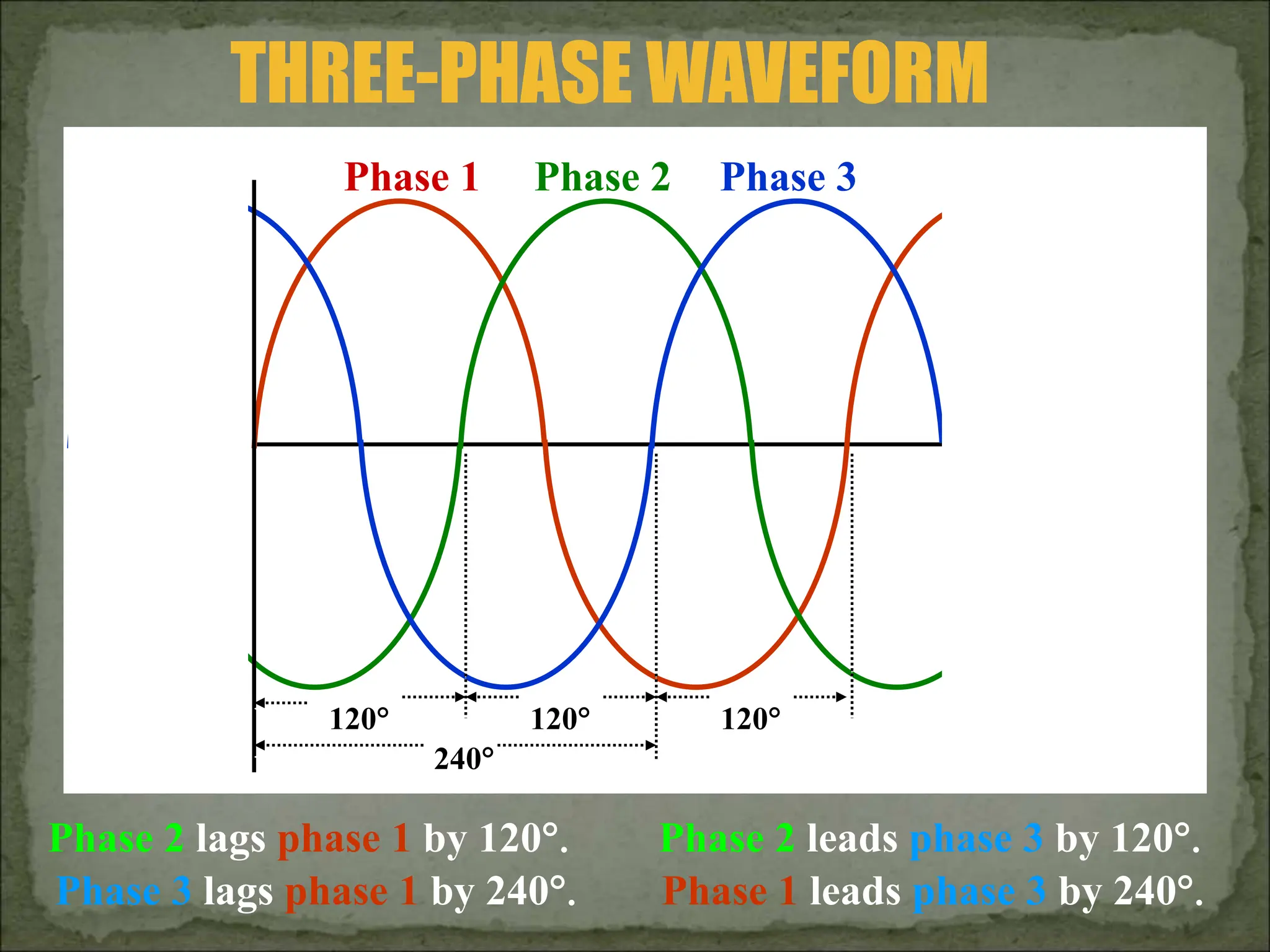
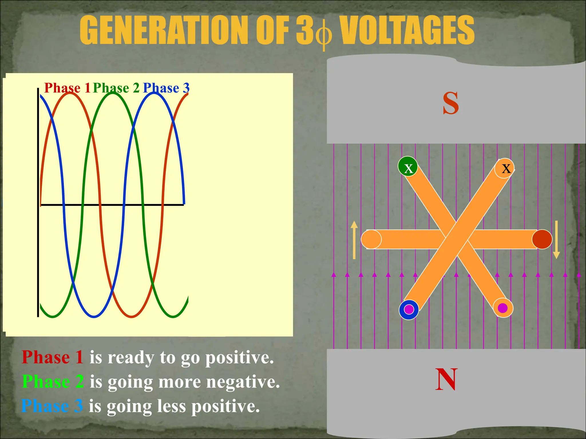
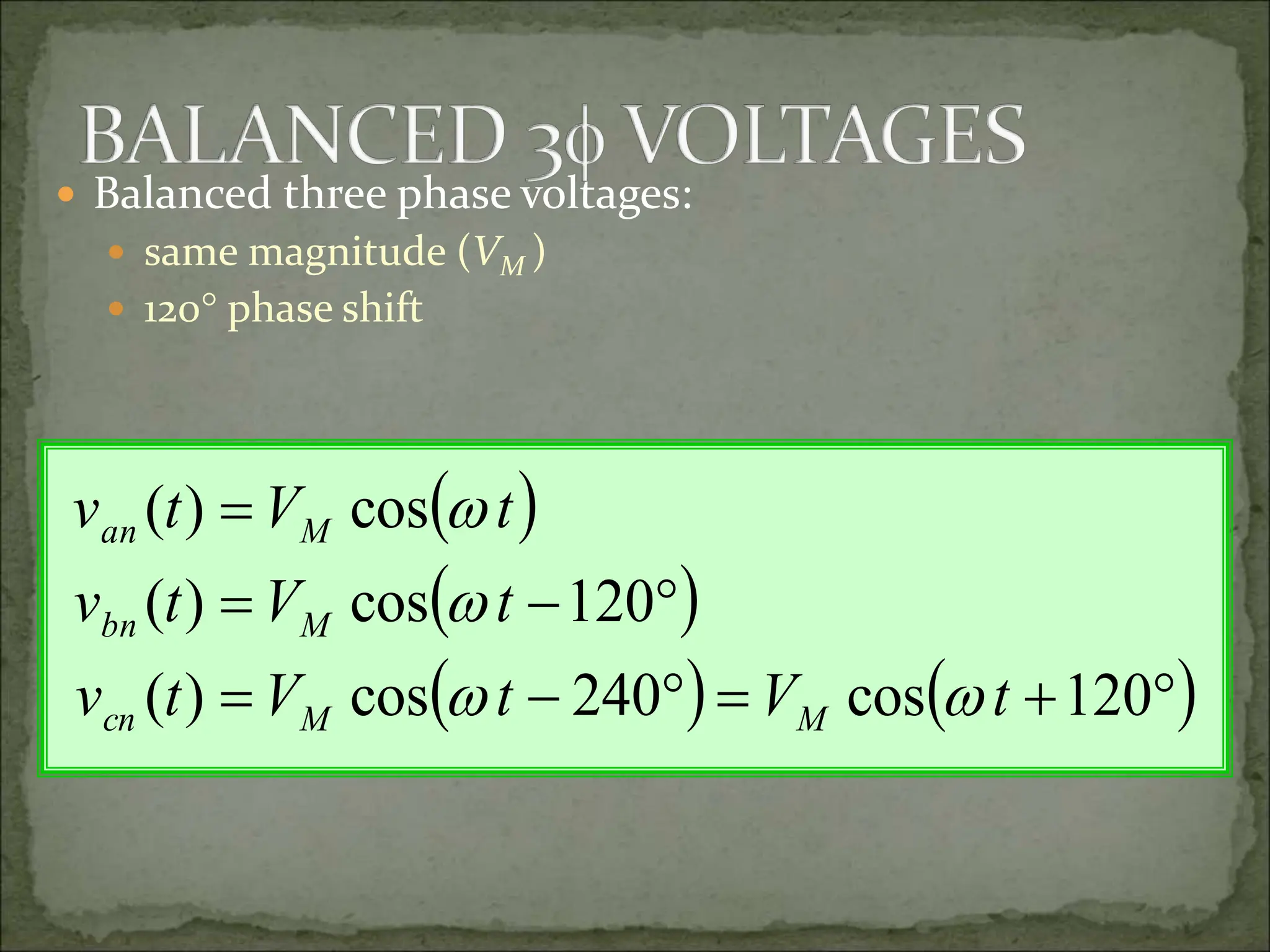
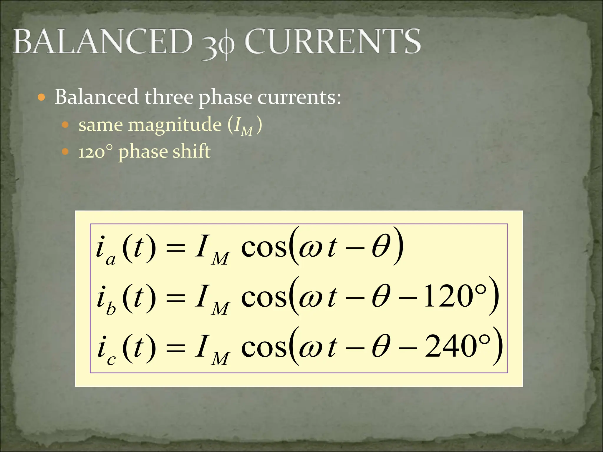
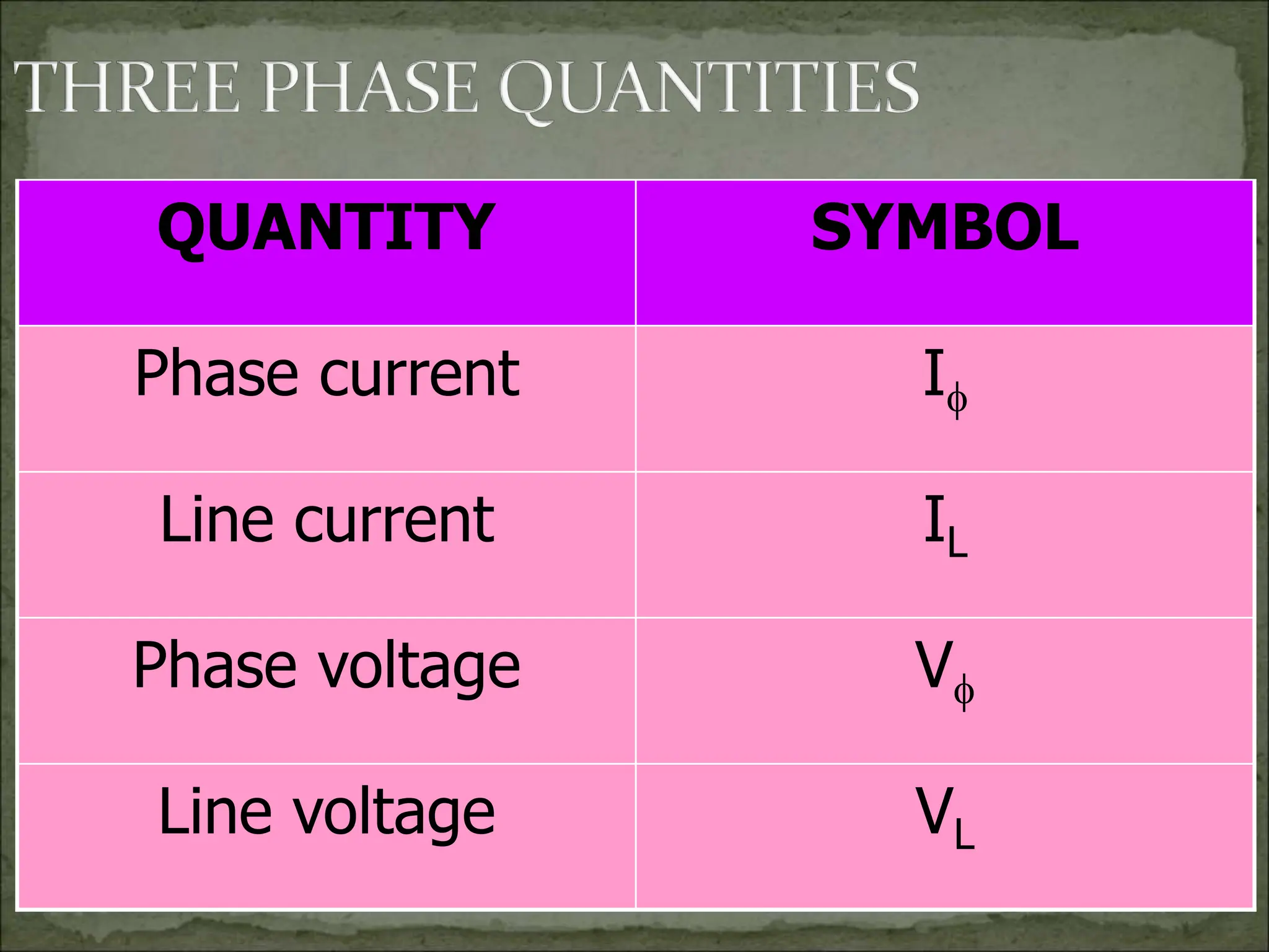
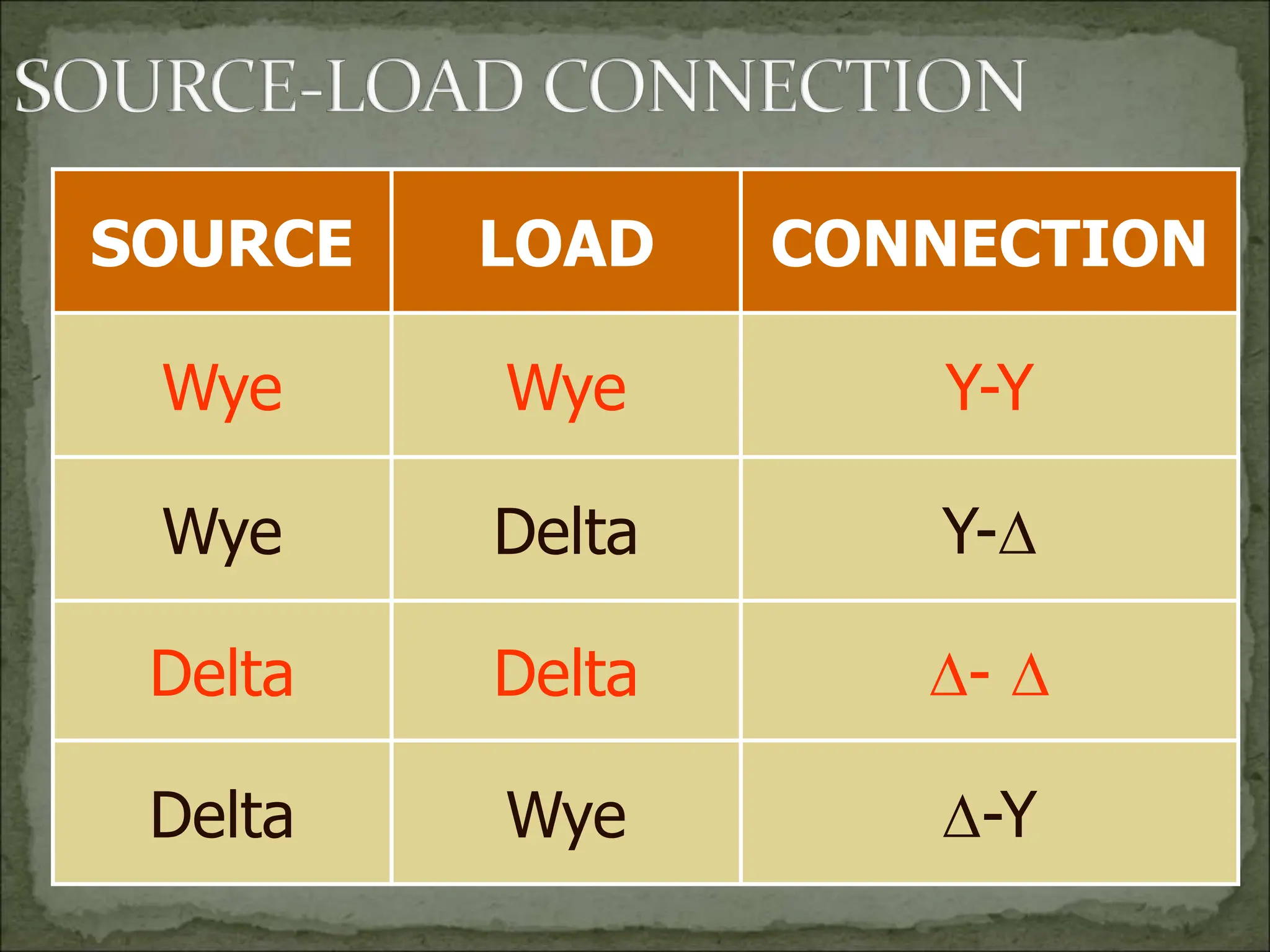
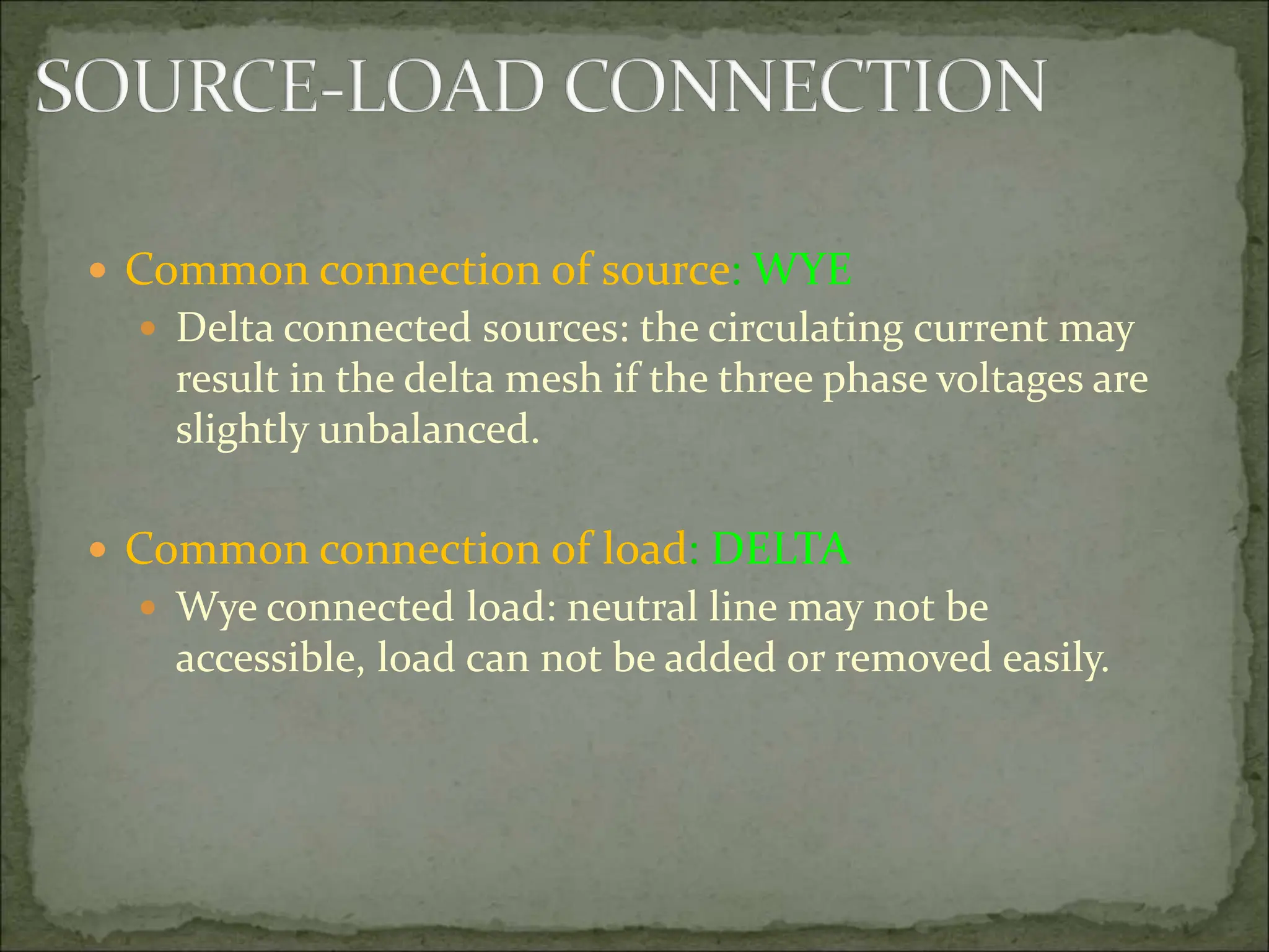
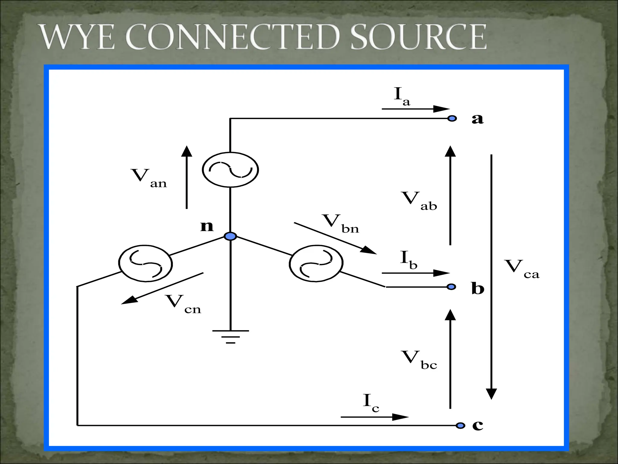
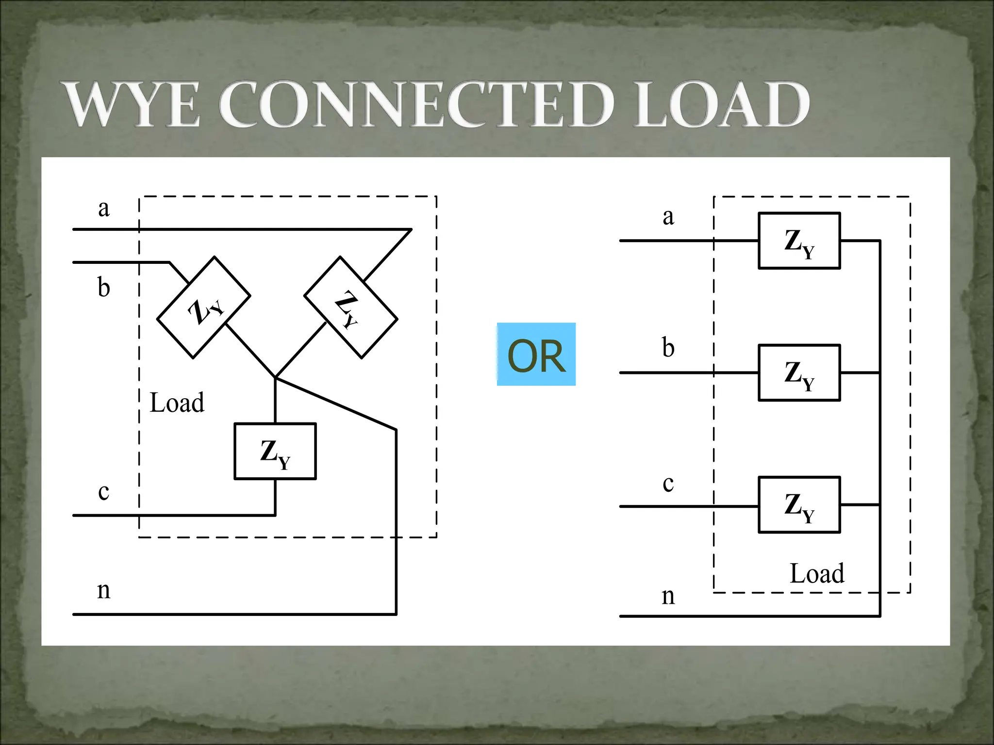
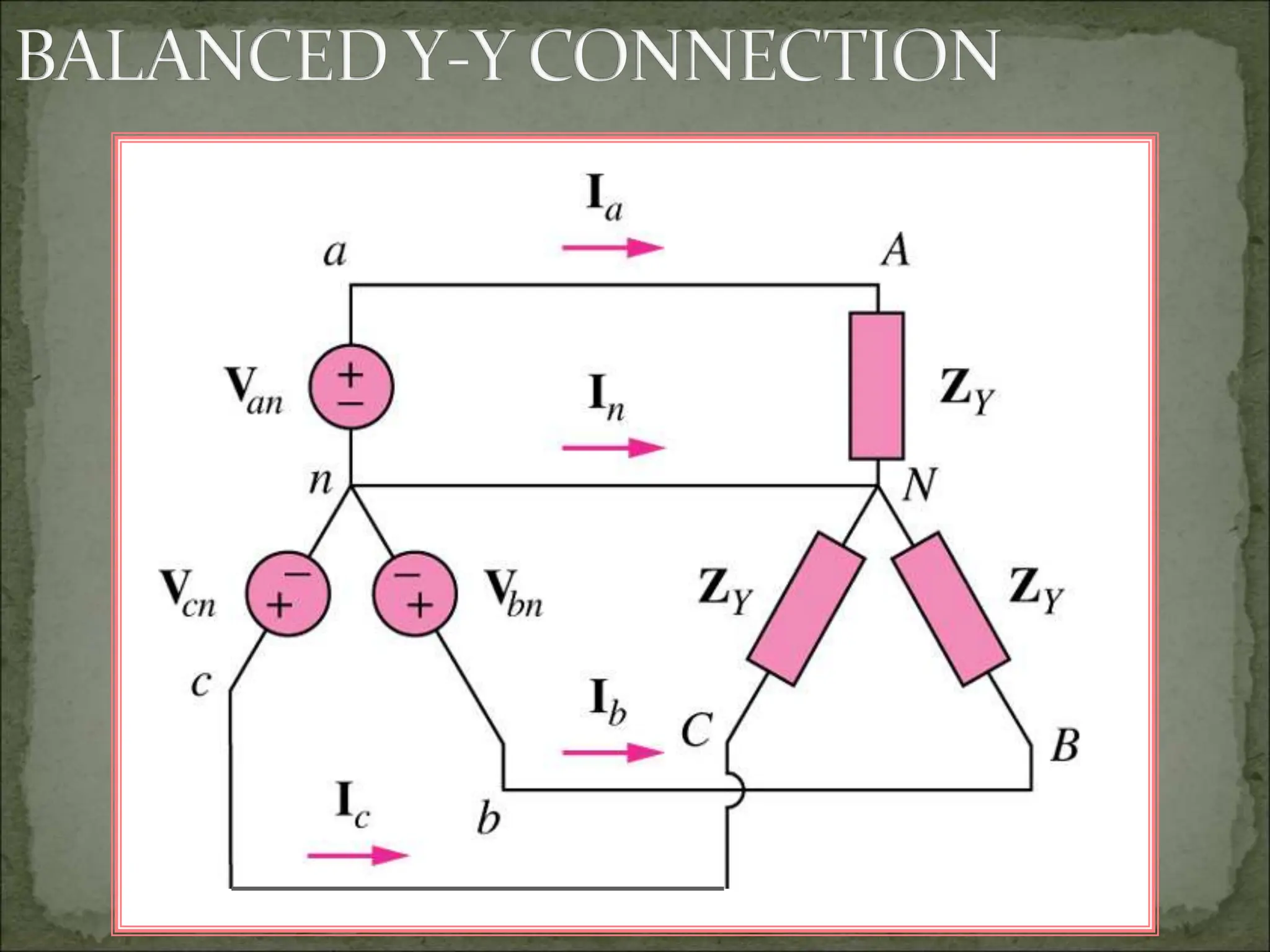
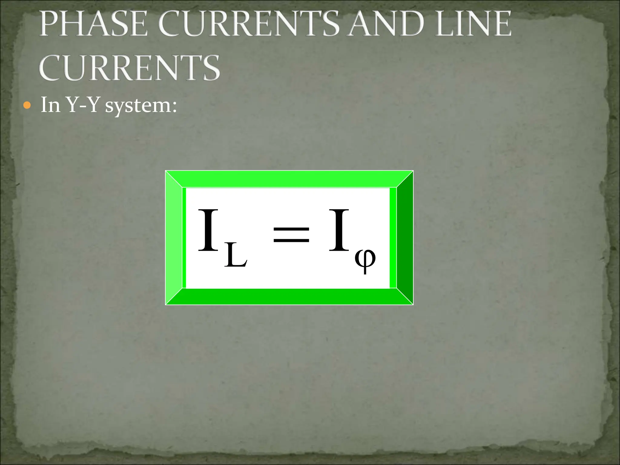
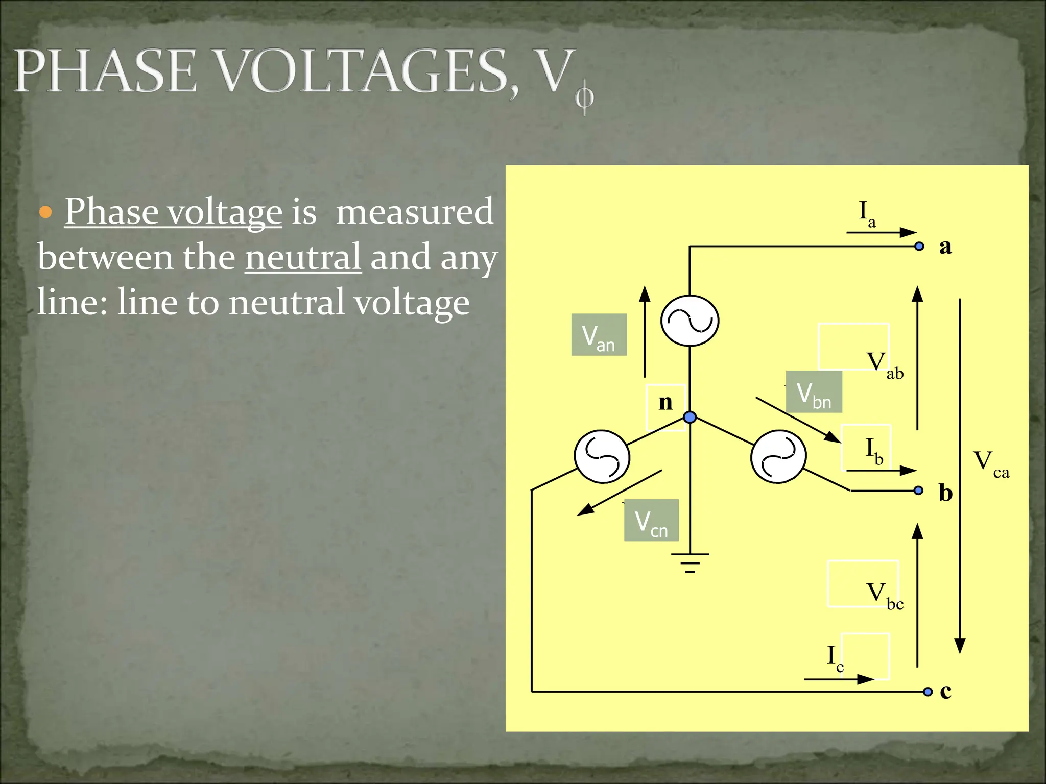
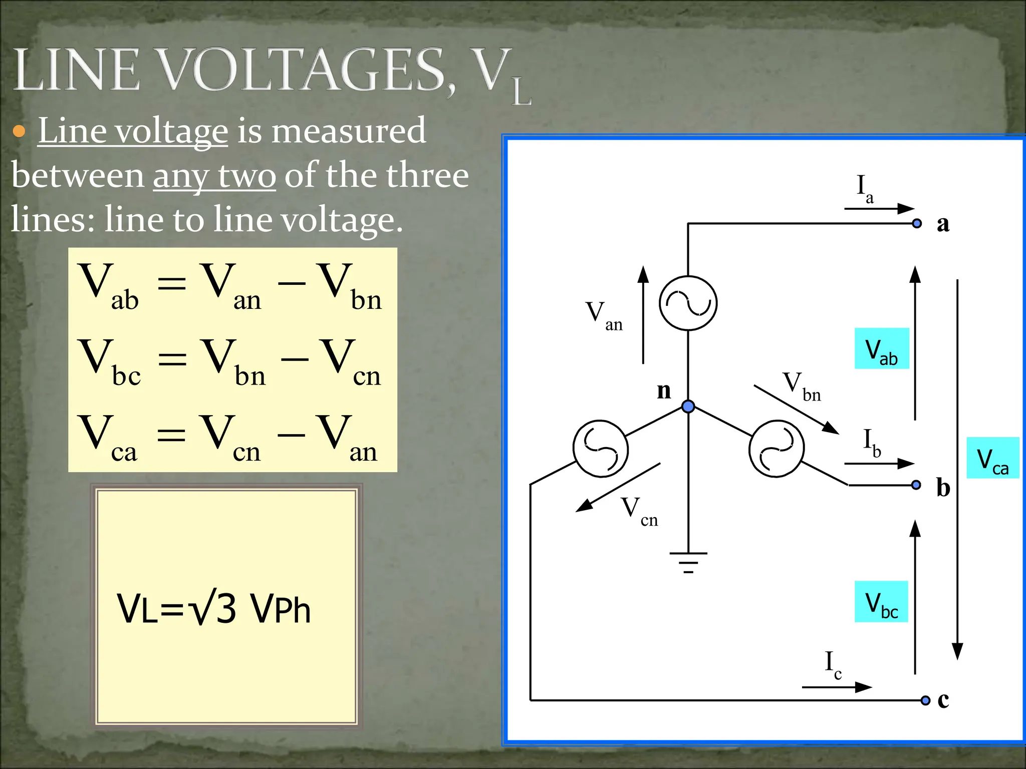
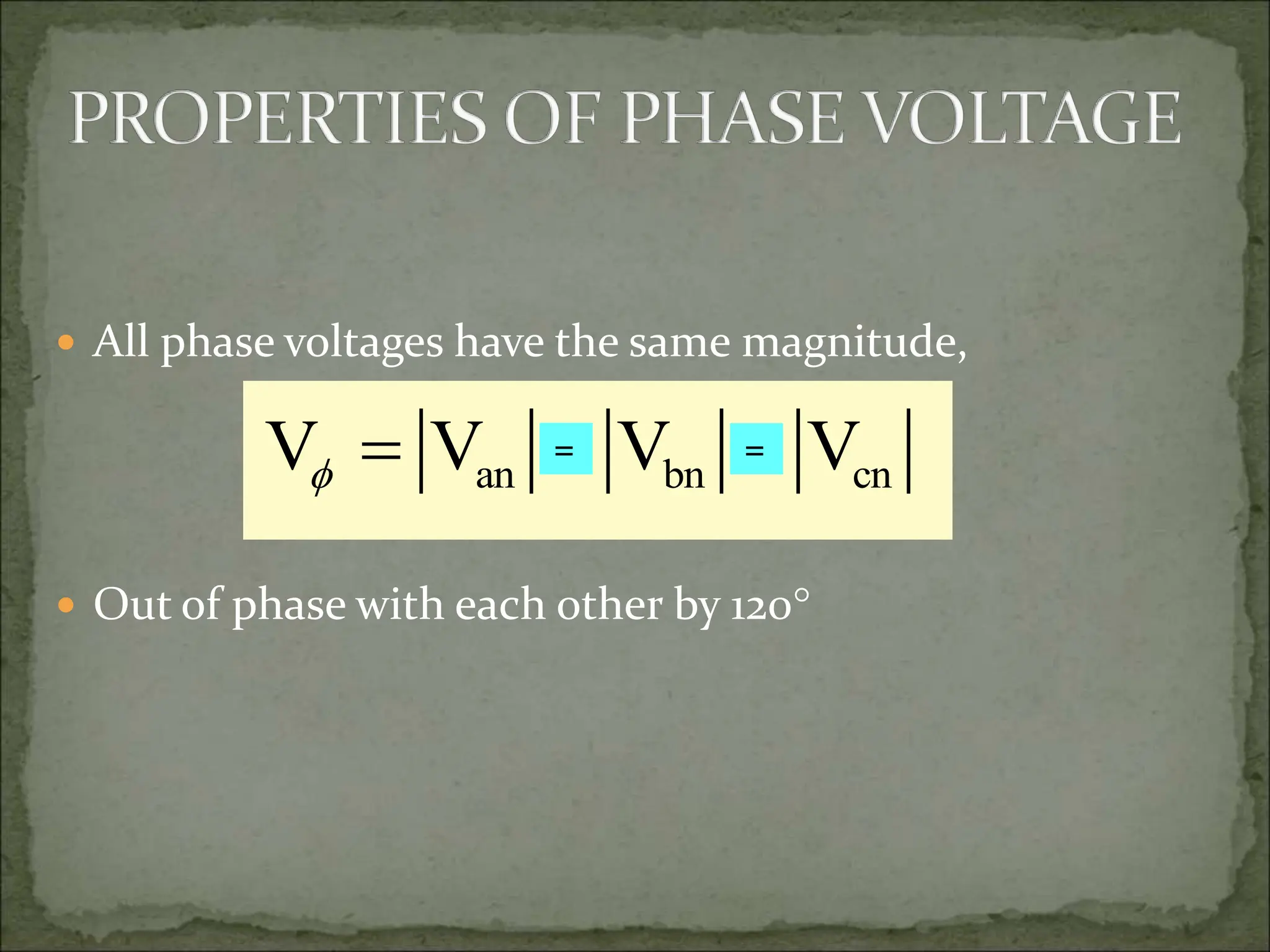
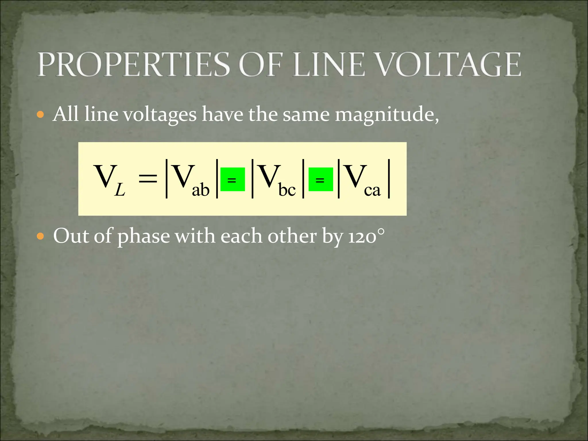
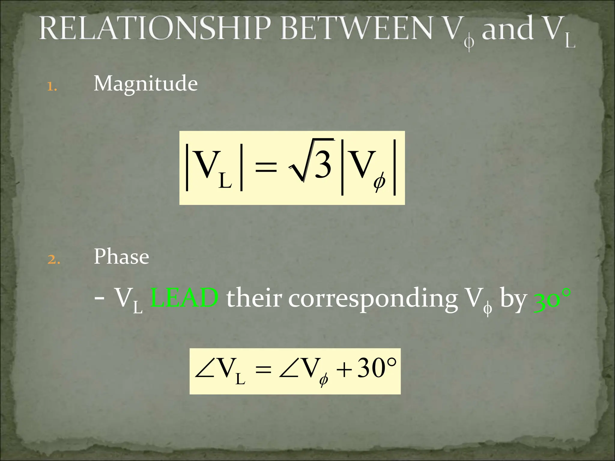
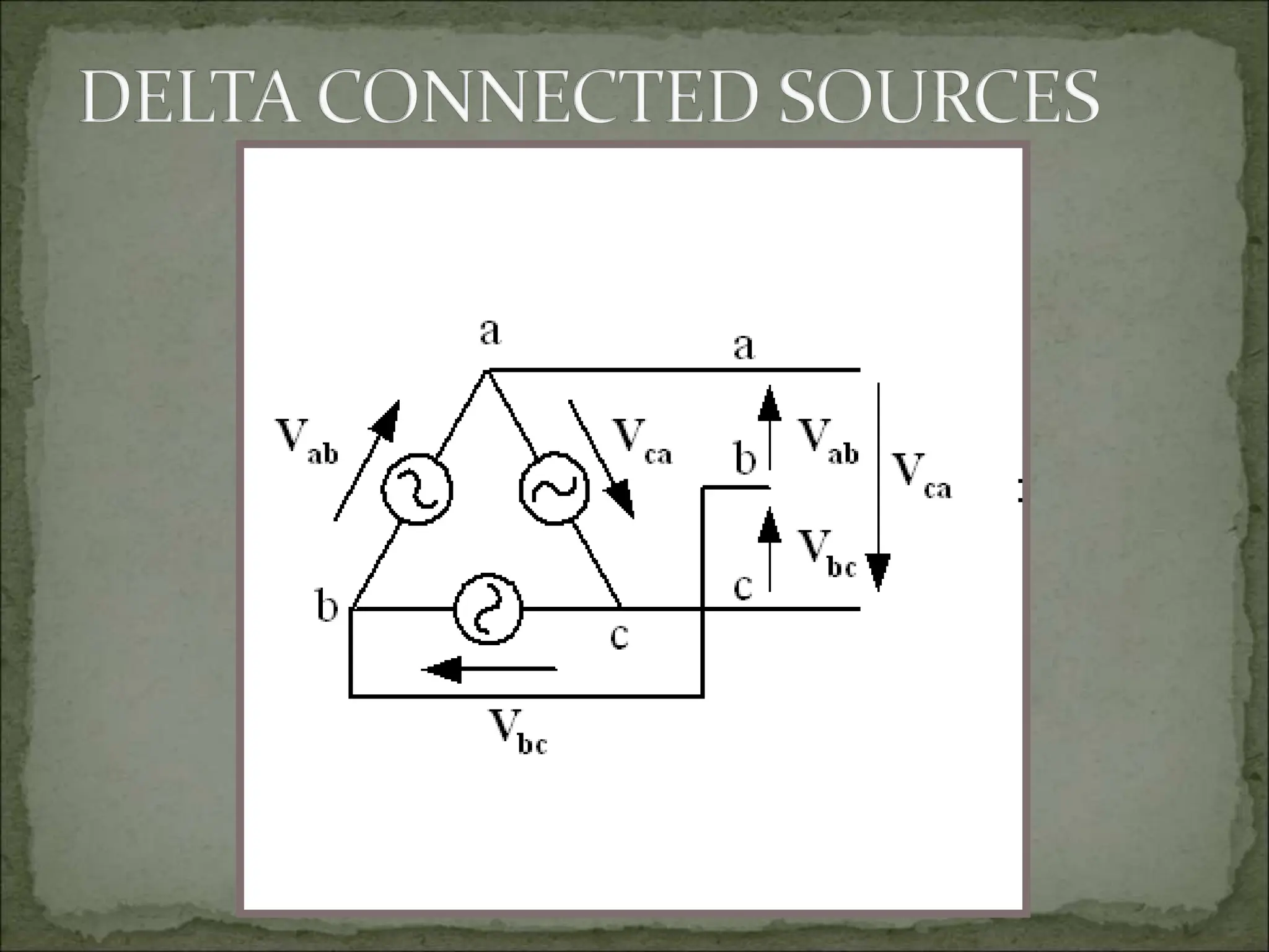
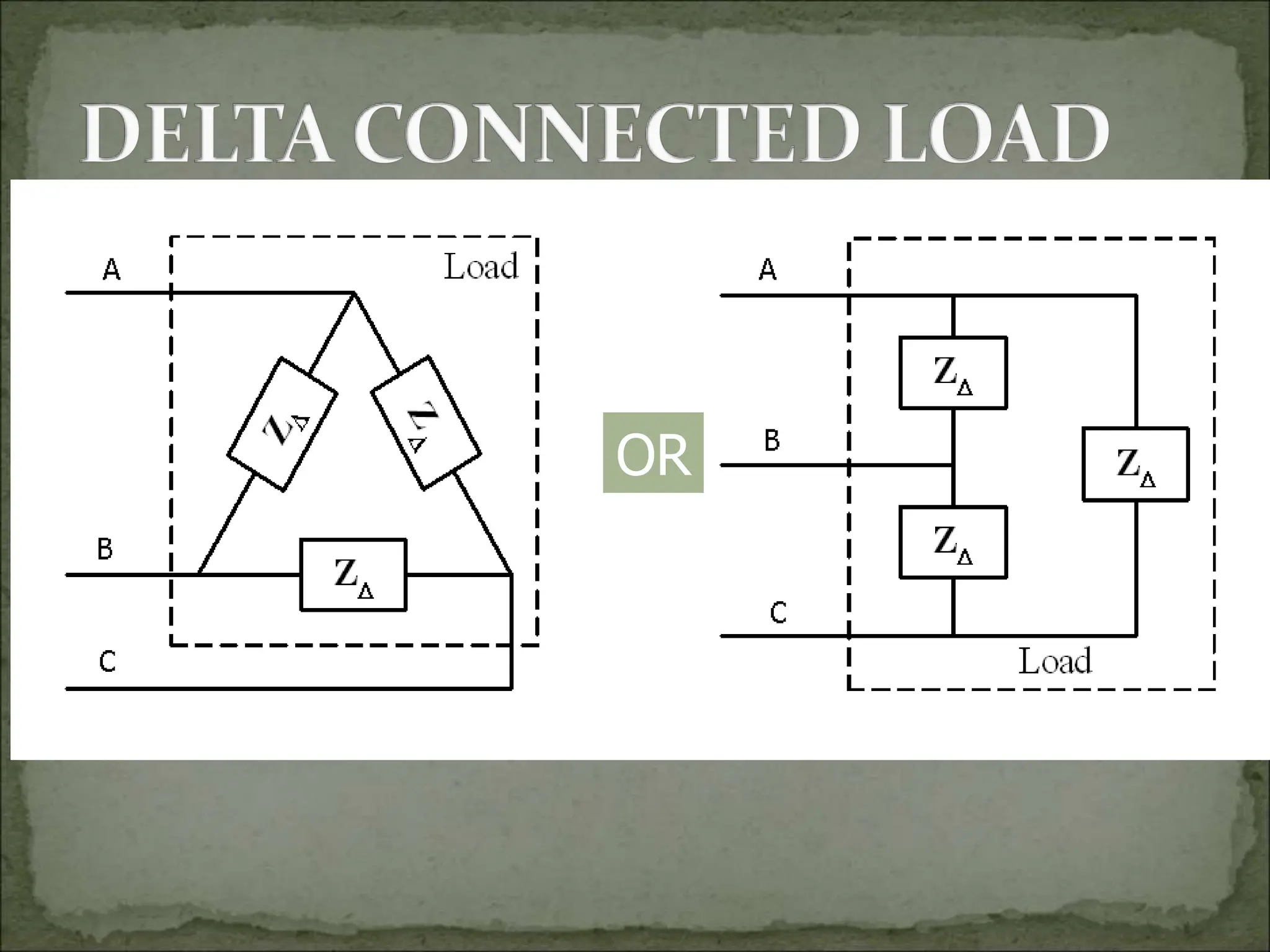
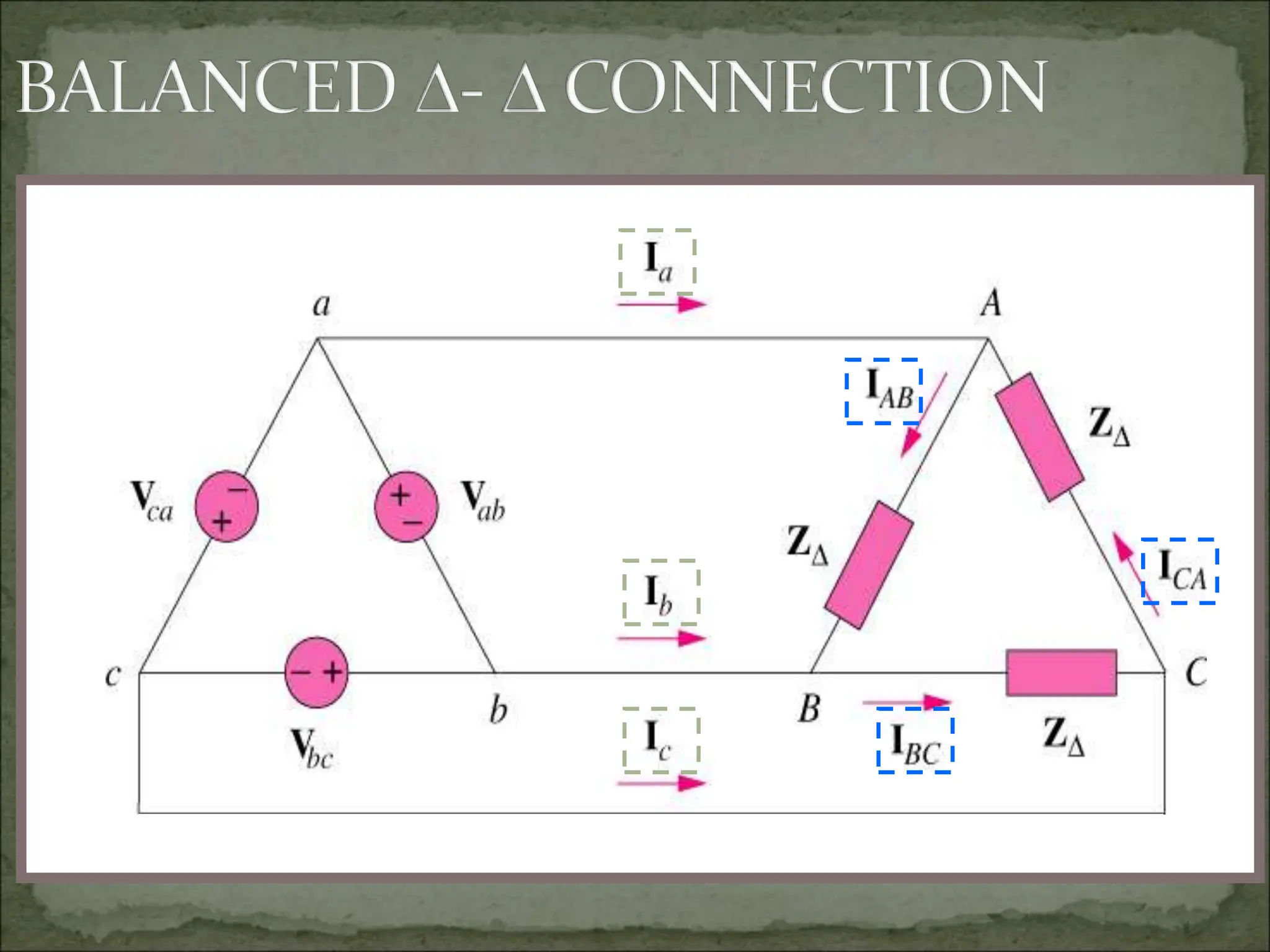
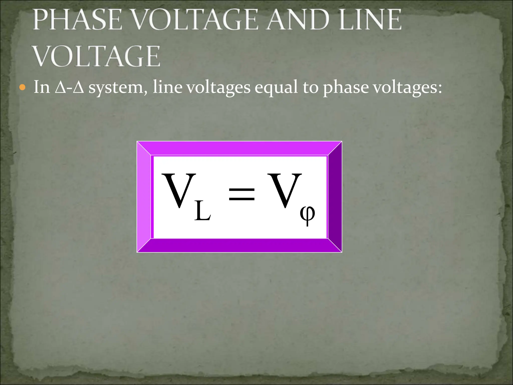
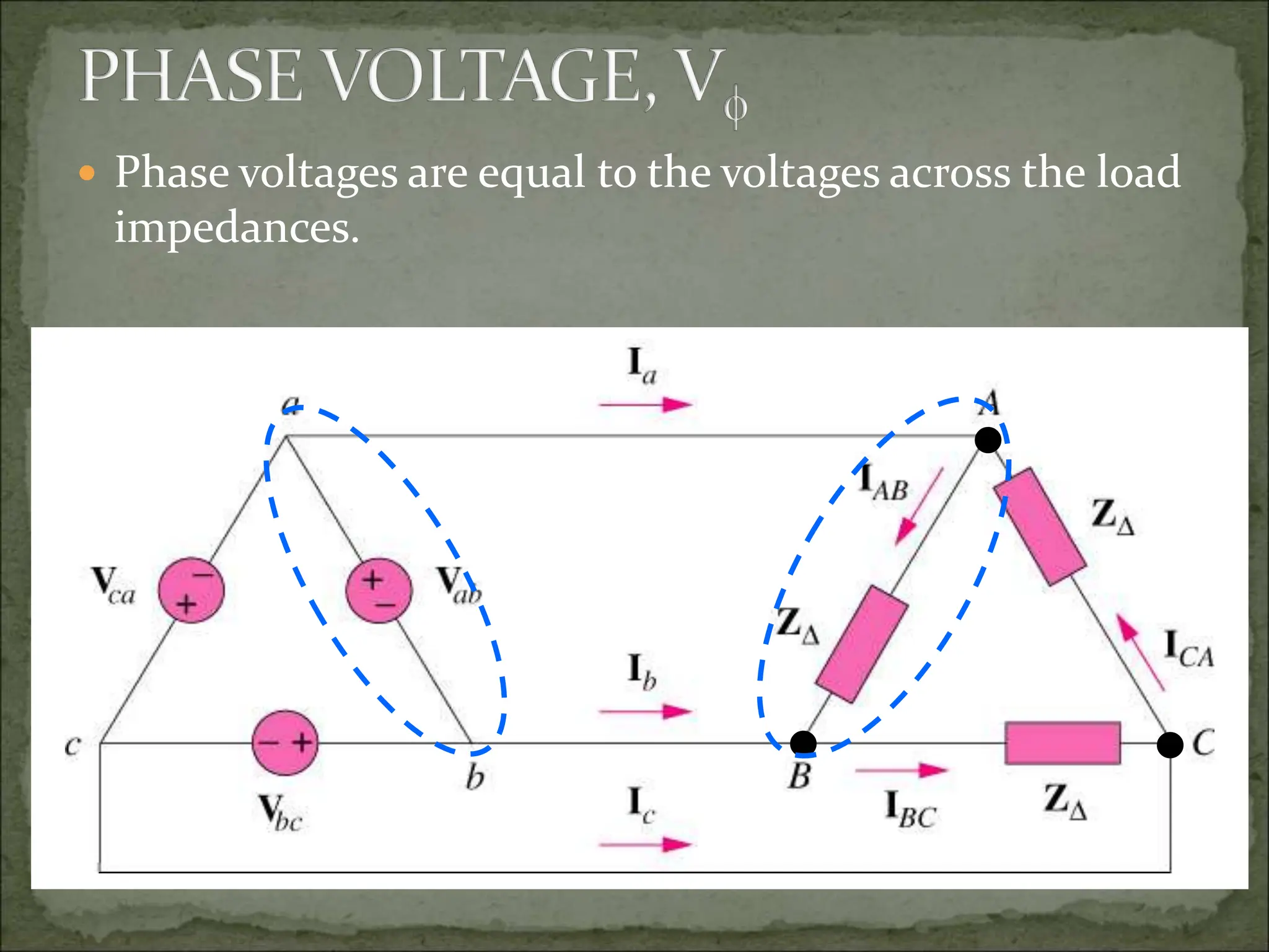
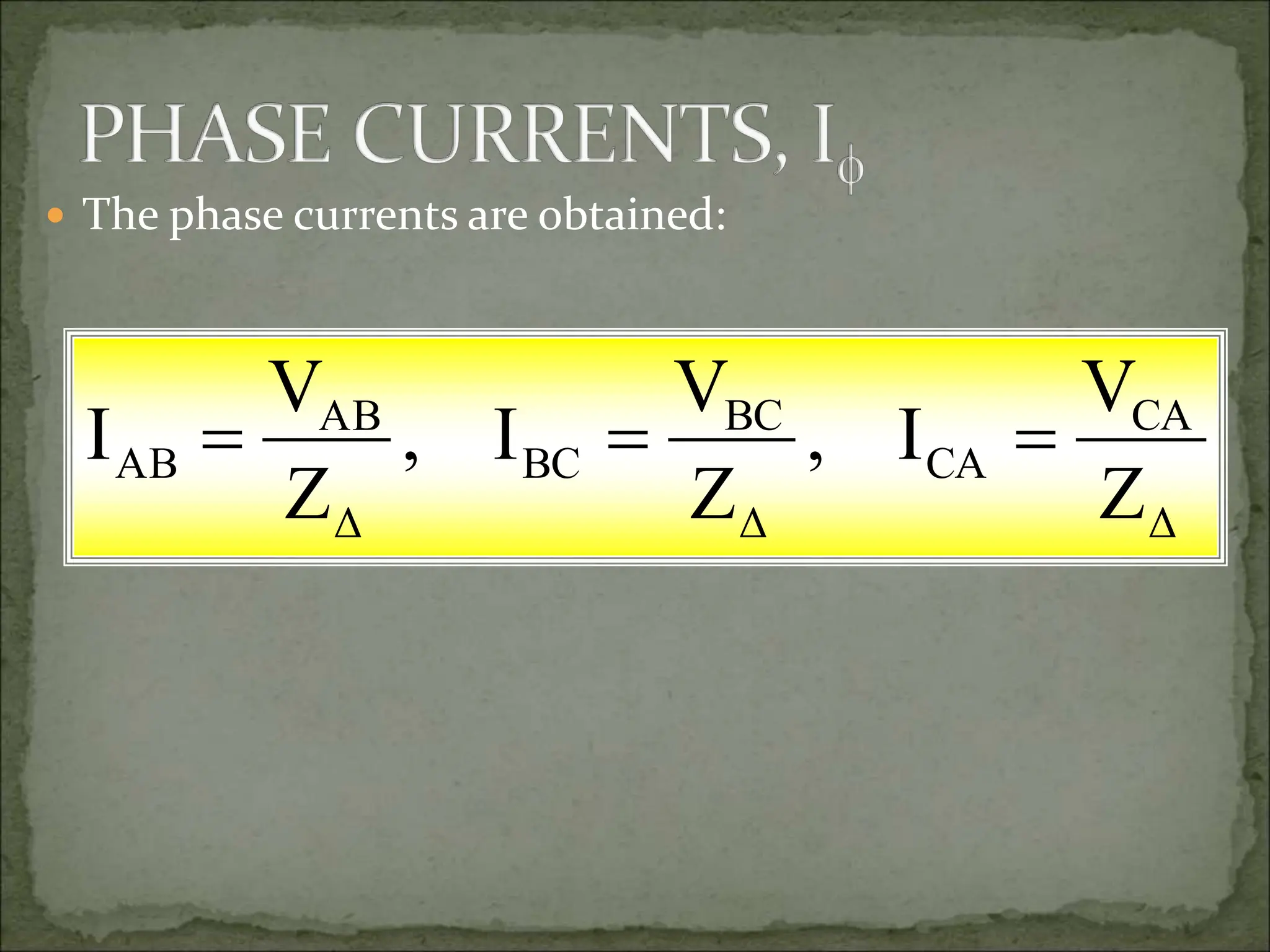
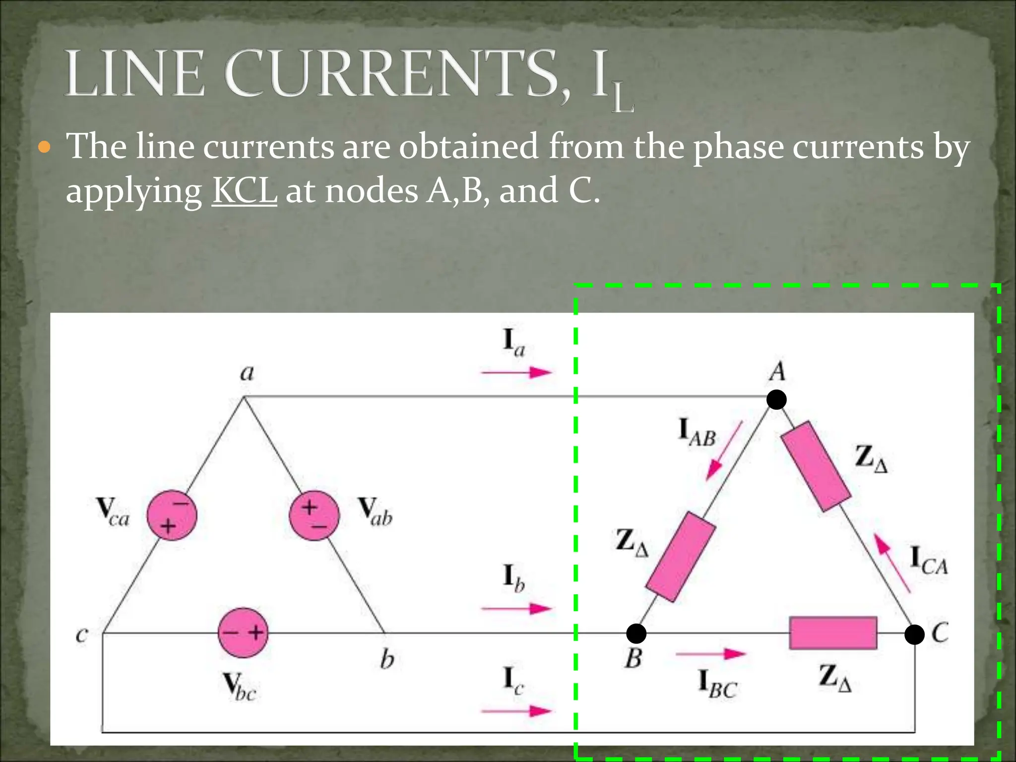
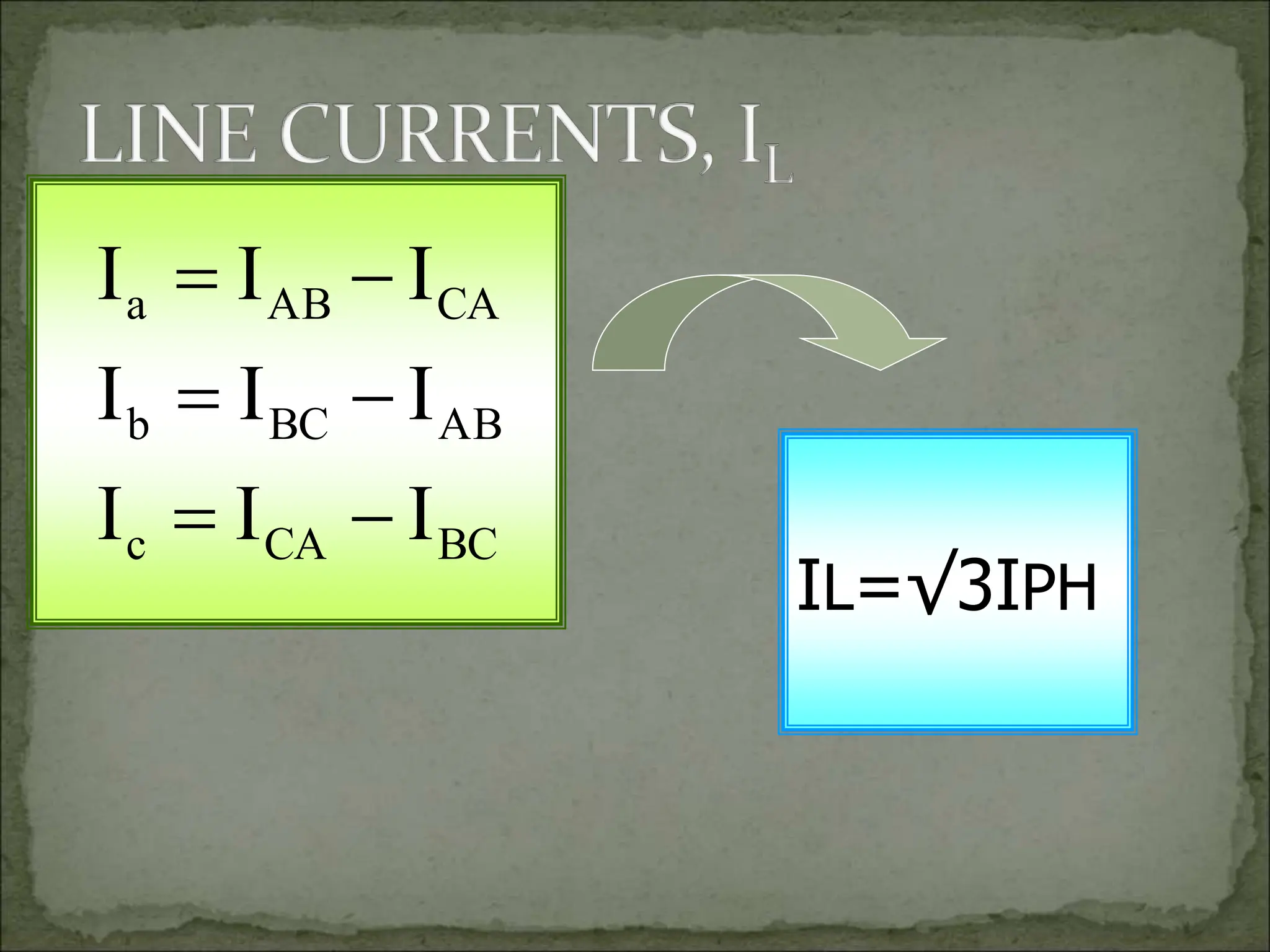
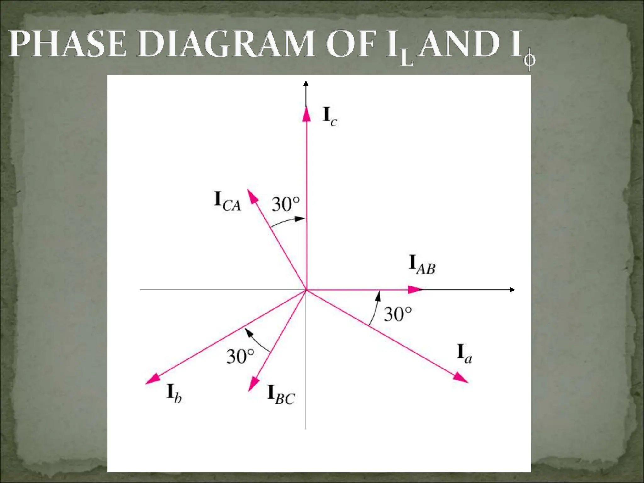
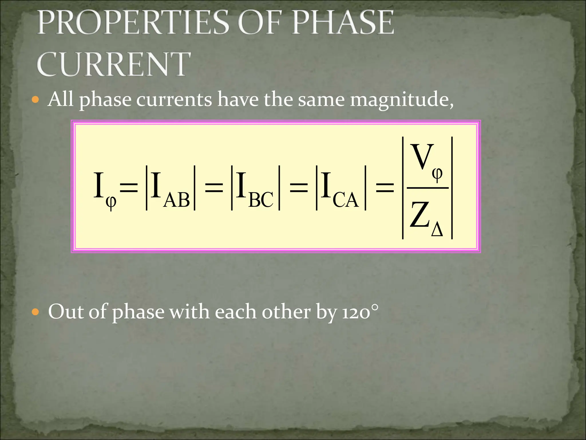
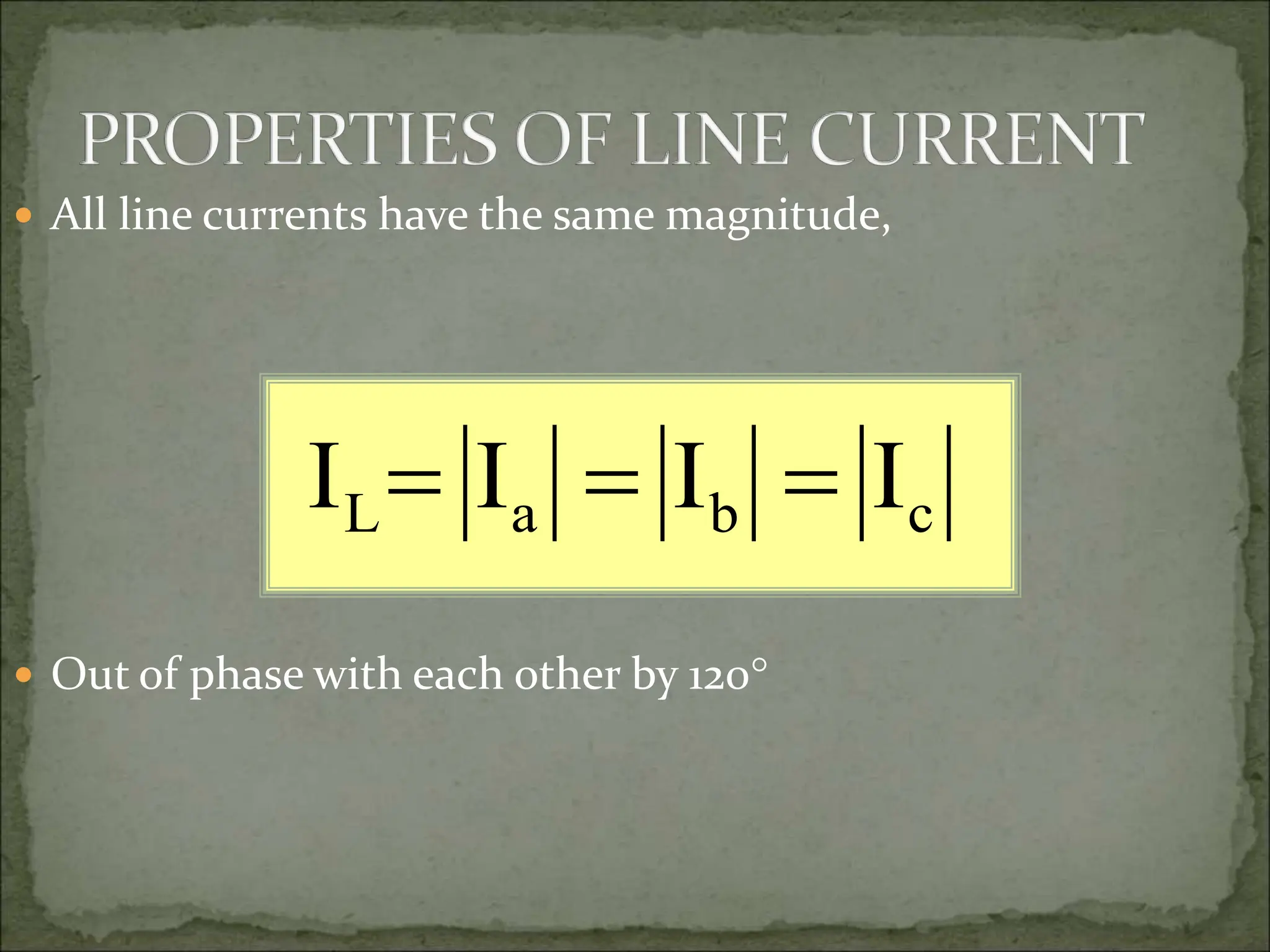
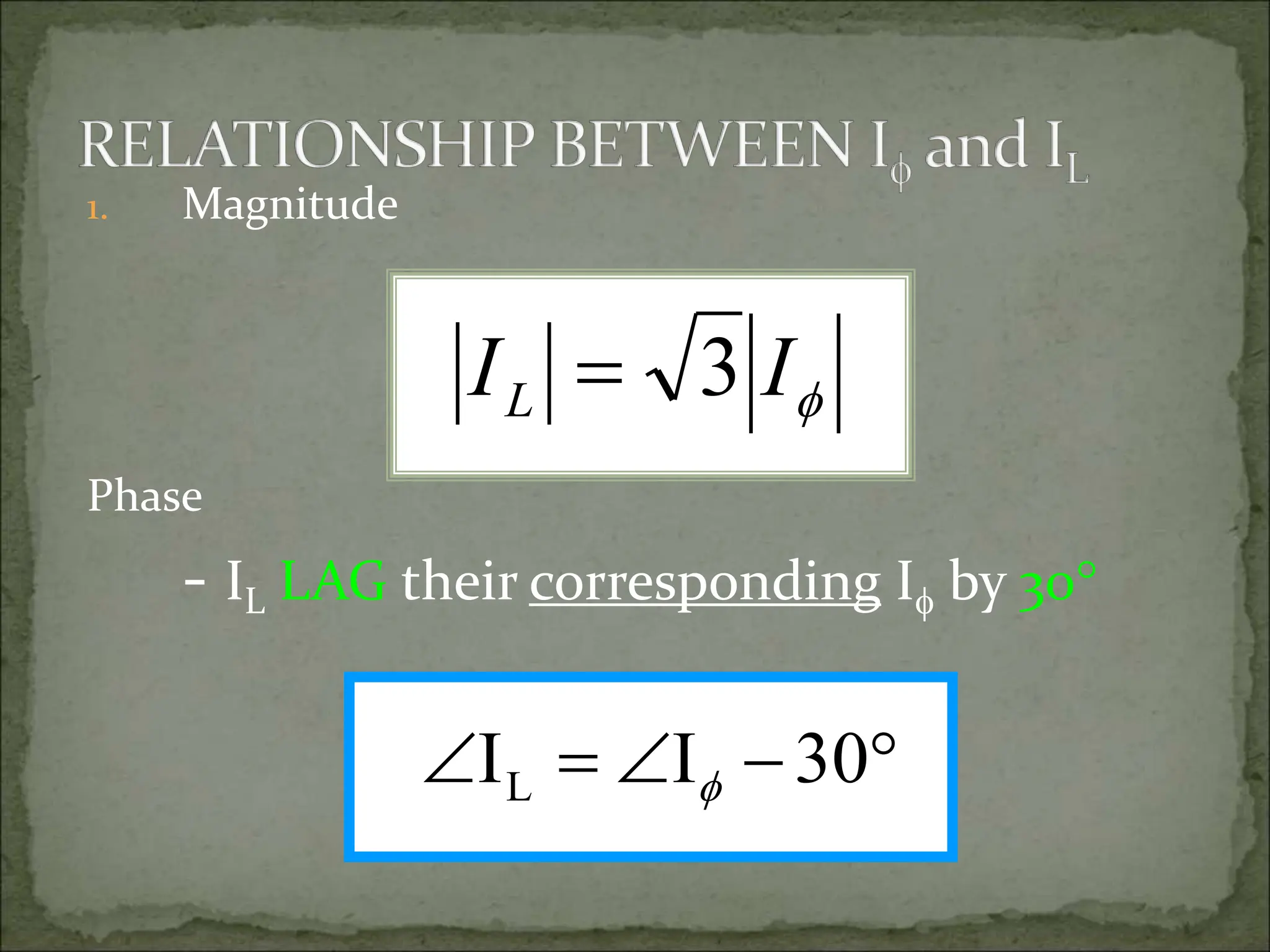
 A generator connected through a pair of wire to a load –
Single Phase Two Wire.
 Vp is the magnitude of the source voltage, and  is the
phase.


p
V


p
V


p
V
 Most common in
practice: two
identical sources
connected to two
loads by two outer
wires and the
neutral: Single
Phase Three
Wire.
 Terminal voltages
have same
magnitude and
the same phase.
Circuit or system in which AC
sources operate at the same
frequency but different phases are
known as polyphase.


p
V


 90
p
V
 Two Phase
System:
 A generator
consists of two
coils placed
perpendicular
to each other
 The voltage
generated by
one lags the
other by 90.
 Three Phase System:
 A generator consists of three coils placed 120 apart.
 The voltage generated are equal in magnitude but, out of
phase by 120.
 Three phase is the most economical polyphase system.
 Three things must be present in order to produce
electrical current:
a) Magnetic field
b) Conductor
c) Relative motion
 Conductor cuts lines of magnetic flux, a voltage is
induced in the conductor
 Direction and Speed are important
GENERATING A SINGLE PHASE
Motion is parallel to the flux.
No voltage is induced.
N
S
N
S
Motion is 45 to flux.
Induced voltage is 0.707 of maximum.
GENERATING A SINGLE PHASE
x
N
S
Motion is perpendicular to flux.
Induced voltage is maximum.
GENERATING A SINGLE PHASE
Motion is 45 to flux.
N
S
Induced voltage is 0.707 of maximum.
GENERATING A SINGLE PHASE
N
S
Motion is parallel to flux.
No voltage is induced.
GENERATING A SINGLE PHASE
N
S
Notice current in the
conductor has reversed.
Induced voltage is
0.707 of maximum.
Motion is 45 to flux.
GENERATING A SINGLE PHASE
N
S
Motion is perpendicular to flux.
Induced voltage is maximum.
GENERATING A SINGLE PHASE
N
S
Motion is 45 to flux.
Induced voltage is 0.707 of maximum.
GENERATING A SINGLE PHASE
Motion is parallel to flux.
N
S
No voltage is induced.
Ready to produce another cycle.
 The generator consists of a rotating magnet (rotor)
surrounded by a stationary winding (stator).
 Three separate windings or coils with terminals a-a’, b-
b’, and c-c’ are physically placed 120 apart around the
stator.
 As the rotor rotates, its magnetic field cuts the flux
from the three coils and induces voltages in the coils.
 The induced voltage have equal magnitude but out of
phase by 120.
GENERATION OF THREE-PHASE AC
N
x
x
S
THREE-PHASE WAVEFORM
Phase 2 lags phase 1 by 120. Phase 2 leads phase 3 by 120.
Phase 3 lags phase 1 by 240. Phase 1 leads phase 3 by 240.
Phase 1 Phase 2 Phase 3
120 120 120
240
120 120 120
240
Phase 1Phase 2 Phase 3
GENERATION OF 3 VOLTAGES
Phase 1 is ready to go positive.
Phase 2 is going more negative.
Phase 3 is going less positive.
N
x
x
S
 Balanced three phase voltages:
 same magnitude (VM )
 120 phase shift
 
 
   










120
cos
240
cos
)
(
120
cos
)
(
cos
)
(
t
V
t
V
t
v
t
V
t
v
t
V
t
v
M
M
cn
M
bn
M
an




 Balanced three phase currents:
 same magnitude (IM )
 120 phase shift
 
 
 










240
cos
)
(
120
cos
)
(
cos
)
(






t
I
t
i
t
I
t
i
t
I
t
i
M
c
M
b
M
a
 Balanced Phase Voltage: all phase voltages are equal in
magnitude and are out of phase with each other by
120.
 Balanced Load: the phase impedances are equal in
magnitude and in phase.
QUANTITY SYMBOL
Phase current I
Line current IL
Phase voltage V
Line voltage VL
 Phase voltage is measured between the neutral and any
line: line to neutral voltage
 Line voltage is measured between any two of the three
lines: line to line voltage.
 Line current (IL) is the current in each line of the source
or load.
 Phase current (I) is the current in each phase of the
source or load.
SOURCE LOAD CONNECTION
Wye Wye Y-Y
Wye Delta Y-
Delta Delta - 
Delta Wye -Y
 Common connection of source: WYE
 Delta connected sources: the circulating current may
result in the delta mesh if the three phase voltages are
slightly unbalanced.
 Common connection of load: DELTA
 Wye connected load: neutral line may not be
accessible, load can not be added or removed easily.
n
a
b
c
Vab
Vbc
Vca
Vbn
Vcn
Van
Ia
Ib
Ic
ZY
ZY
ZY
a
c
b
n
Load
ZY
Z
Y
Z
Y
a
b
c
Load
n
OR
 In Y-Y system:
φ
L I
I 
 Phase voltage is measured
between the neutral and any
line: line to neutral voltage
n
a
b
c
Vab
Vbc
Vca
Vbn
Vcn
Van
Ia
Ib
Ic
Van
Vbn
Vcn
 Line voltage is measured
between any two of the three
lines: line to line voltage.
n
a
b
c
Vab
Vbc
Vca
Vbn
Vcn
Van
Ia
Ib
Ic
Vab
Vbc
Vca
an
cn
ca
cn
bn
bc
bn
an
ab
V
V
V
V
V
V
V
V
V






VL=√3 VPh
 All phase voltages have the same magnitude,
 Out of phase with each other by 120
an bn cn
V V V V
   
= =
 All line voltages have the same magnitude,
 Out of phase with each other by 120
ab bc ca
V V V V
L   
= =




 30
V
VL 
1. Magnitude
2. Phase
- VL LEAD their corresponding V by 30
L
V 3 V

OR
 In - system, line voltages equal to phase voltages:
φ
L V
V 
 Phase voltages are equal to the voltages across the load
impedances.



Δ
CA
CA
Δ
BC
BC
Δ
AB
AB
Z
V
I
,
Z
V
I
,
Z
V
I 


 The phase currents are obtained:
 The line currents are obtained from the phase currents by
applying KCL at nodes A,B, and C.



BC
CA
c
AB
BC
b
CA
AB
a
I
I
I
I
I
I
I
I
I






IL=√3IPH
 All phase currents have the same magnitude,
 Out of phase with each other by 120
Δ
φ
CA
BC
AB
φ
Z
V
I
I
I
I 



 All line currents have the same magnitude,
 Out of phase with each other by 120
c
b
a
L I
I
I
I 


1. Magnitude
Phase
- IL LAG their corresponding I by 30

I
IL 3





 30
I
IL 
3phase unit 2.ppt

3phase unit 2.ppt

  • 1.
     A generatorconnected through a pair of wire to a load – Single Phase Two Wire.  Vp is the magnitude of the source voltage, and  is the phase.   p V
  • 2.
      p V   p V  Most commonin practice: two identical sources connected to two loads by two outer wires and the neutral: Single Phase Three Wire.  Terminal voltages have same magnitude and the same phase.
  • 3.
    Circuit or systemin which AC sources operate at the same frequency but different phases are known as polyphase.
  • 4.
      p V    90 p V  TwoPhase System:  A generator consists of two coils placed perpendicular to each other  The voltage generated by one lags the other by 90.
  • 5.
     Three PhaseSystem:  A generator consists of three coils placed 120 apart.  The voltage generated are equal in magnitude but, out of phase by 120.  Three phase is the most economical polyphase system.
  • 9.
     Three thingsmust be present in order to produce electrical current: a) Magnetic field b) Conductor c) Relative motion  Conductor cuts lines of magnetic flux, a voltage is induced in the conductor  Direction and Speed are important
  • 10.
    GENERATING A SINGLEPHASE Motion is parallel to the flux. No voltage is induced. N S
  • 11.
    N S Motion is 45to flux. Induced voltage is 0.707 of maximum. GENERATING A SINGLE PHASE
  • 12.
    GENERATING A SINGLEPHASE x N S Motion is perpendicular to flux. Induced voltage is maximum.
  • 13.
    GENERATING A SINGLEPHASE Motion is 45 to flux. N S Induced voltage is 0.707 of maximum.
  • 14.
    GENERATING A SINGLEPHASE N S Motion is parallel to flux. No voltage is induced.
  • 15.
    GENERATING A SINGLEPHASE N S Notice current in the conductor has reversed. Induced voltage is 0.707 of maximum. Motion is 45 to flux.
  • 16.
    GENERATING A SINGLEPHASE N S Motion is perpendicular to flux. Induced voltage is maximum.
  • 17.
    GENERATING A SINGLEPHASE N S Motion is 45 to flux. Induced voltage is 0.707 of maximum.
  • 18.
    GENERATING A SINGLEPHASE Motion is parallel to flux. N S No voltage is induced. Ready to produce another cycle.
  • 20.
     The generatorconsists of a rotating magnet (rotor) surrounded by a stationary winding (stator).  Three separate windings or coils with terminals a-a’, b- b’, and c-c’ are physically placed 120 apart around the stator.  As the rotor rotates, its magnetic field cuts the flux from the three coils and induces voltages in the coils.  The induced voltage have equal magnitude but out of phase by 120.
  • 21.
  • 22.
    THREE-PHASE WAVEFORM Phase 2lags phase 1 by 120. Phase 2 leads phase 3 by 120. Phase 3 lags phase 1 by 240. Phase 1 leads phase 3 by 240. Phase 1 Phase 2 Phase 3 120 120 120 240 120 120 120 240
  • 23.
    Phase 1Phase 2Phase 3 GENERATION OF 3 VOLTAGES Phase 1 is ready to go positive. Phase 2 is going more negative. Phase 3 is going less positive. N x x S
  • 25.
     Balanced threephase voltages:  same magnitude (VM )  120 phase shift                   120 cos 240 cos ) ( 120 cos ) ( cos ) ( t V t V t v t V t v t V t v M M cn M bn M an    
  • 26.
     Balanced threephase currents:  same magnitude (IM )  120 phase shift                 240 cos ) ( 120 cos ) ( cos ) (       t I t i t I t i t I t i M c M b M a
  • 27.
     Balanced PhaseVoltage: all phase voltages are equal in magnitude and are out of phase with each other by 120.  Balanced Load: the phase impedances are equal in magnitude and in phase.
  • 28.
    QUANTITY SYMBOL Phase currentI Line current IL Phase voltage V Line voltage VL
  • 29.
     Phase voltageis measured between the neutral and any line: line to neutral voltage  Line voltage is measured between any two of the three lines: line to line voltage.  Line current (IL) is the current in each line of the source or load.  Phase current (I) is the current in each phase of the source or load.
  • 31.
    SOURCE LOAD CONNECTION WyeWye Y-Y Wye Delta Y- Delta Delta -  Delta Wye -Y
  • 32.
     Common connectionof source: WYE  Delta connected sources: the circulating current may result in the delta mesh if the three phase voltages are slightly unbalanced.  Common connection of load: DELTA  Wye connected load: neutral line may not be accessible, load can not be added or removed easily.
  • 34.
  • 35.
  • 37.
     In Y-Ysystem: φ L I I 
  • 38.
     Phase voltageis measured between the neutral and any line: line to neutral voltage n a b c Vab Vbc Vca Vbn Vcn Van Ia Ib Ic Van Vbn Vcn
  • 39.
     Line voltageis measured between any two of the three lines: line to line voltage. n a b c Vab Vbc Vca Vbn Vcn Van Ia Ib Ic Vab Vbc Vca an cn ca cn bn bc bn an ab V V V V V V V V V       VL=√3 VPh
  • 40.
     All phasevoltages have the same magnitude,  Out of phase with each other by 120 an bn cn V V V V     = =
  • 41.
     All linevoltages have the same magnitude,  Out of phase with each other by 120 ab bc ca V V V V L    = =
  • 42.
         30 V VL  1.Magnitude 2. Phase - VL LEAD their corresponding V by 30 L V 3 V 
  • 45.
  • 47.
     In -system, line voltages equal to phase voltages: φ L V V 
  • 48.
     Phase voltagesare equal to the voltages across the load impedances.   
  • 49.
  • 50.
     The linecurrents are obtained from the phase currents by applying KCL at nodes A,B, and C.   
  • 51.
  • 53.
     All phasecurrents have the same magnitude,  Out of phase with each other by 120 Δ φ CA BC AB φ Z V I I I I    
  • 54.
     All linecurrents have the same magnitude,  Out of phase with each other by 120 c b a L I I I I   
  • 55.
    1. Magnitude Phase - ILLAG their corresponding I by 30  I IL 3       30 I IL 