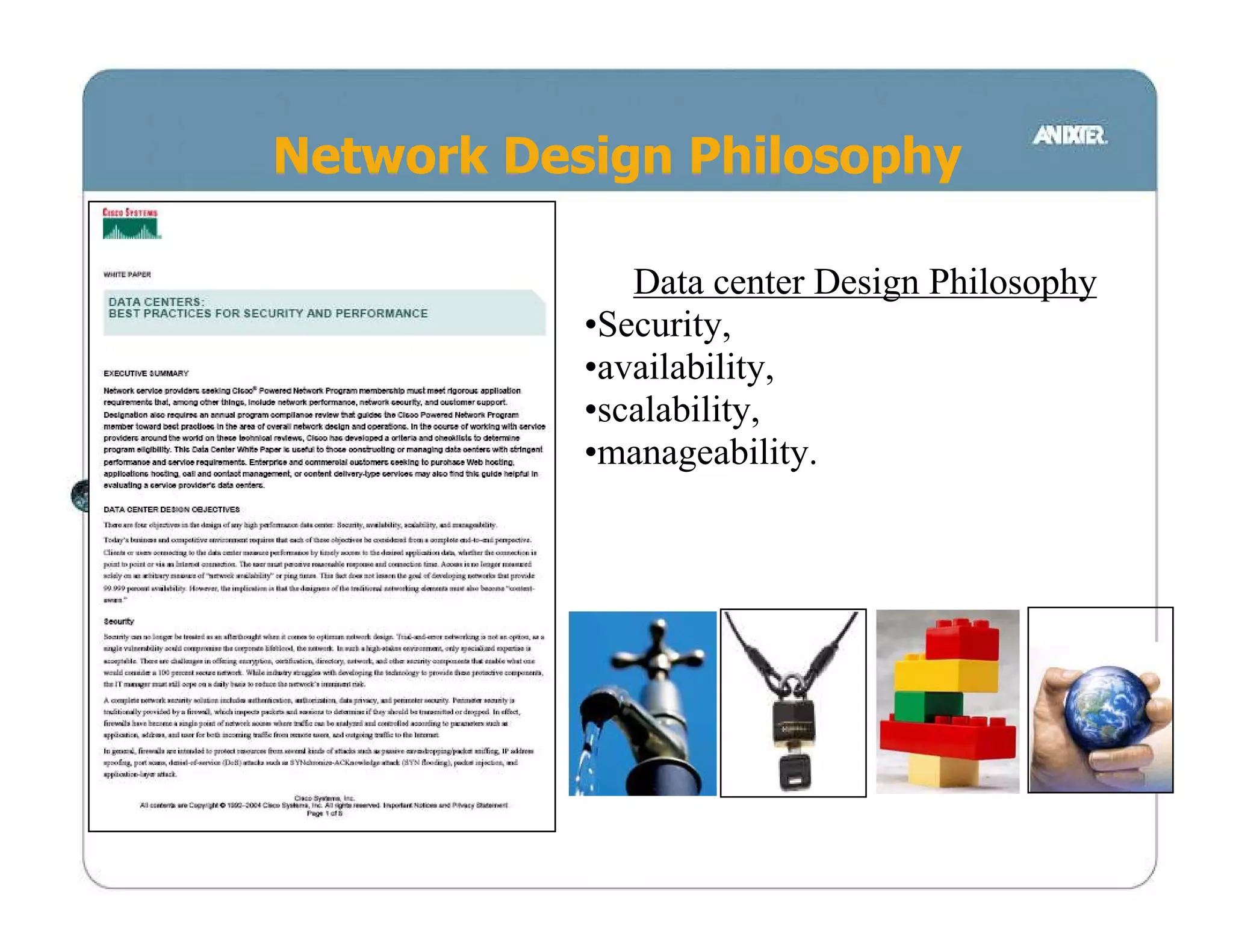
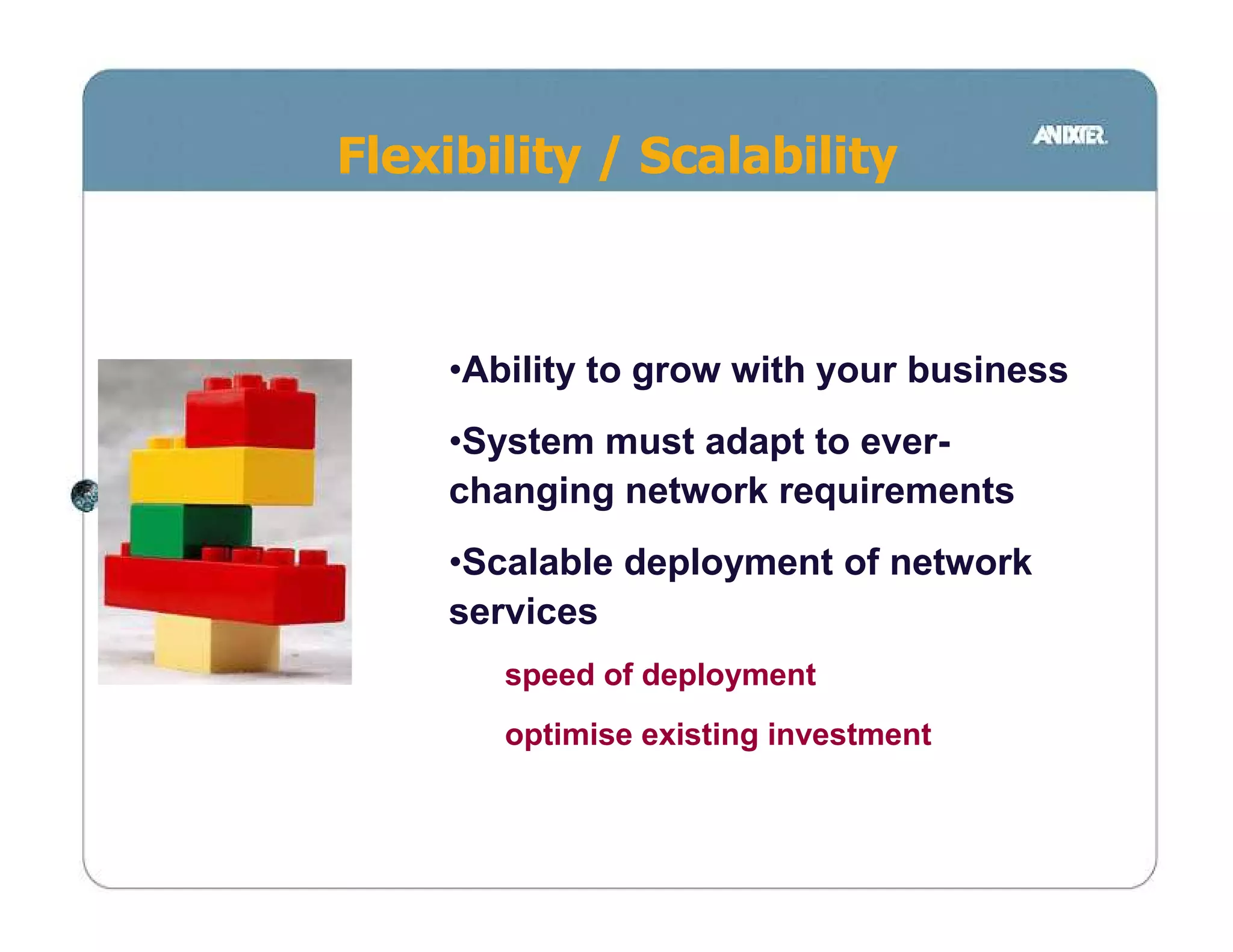
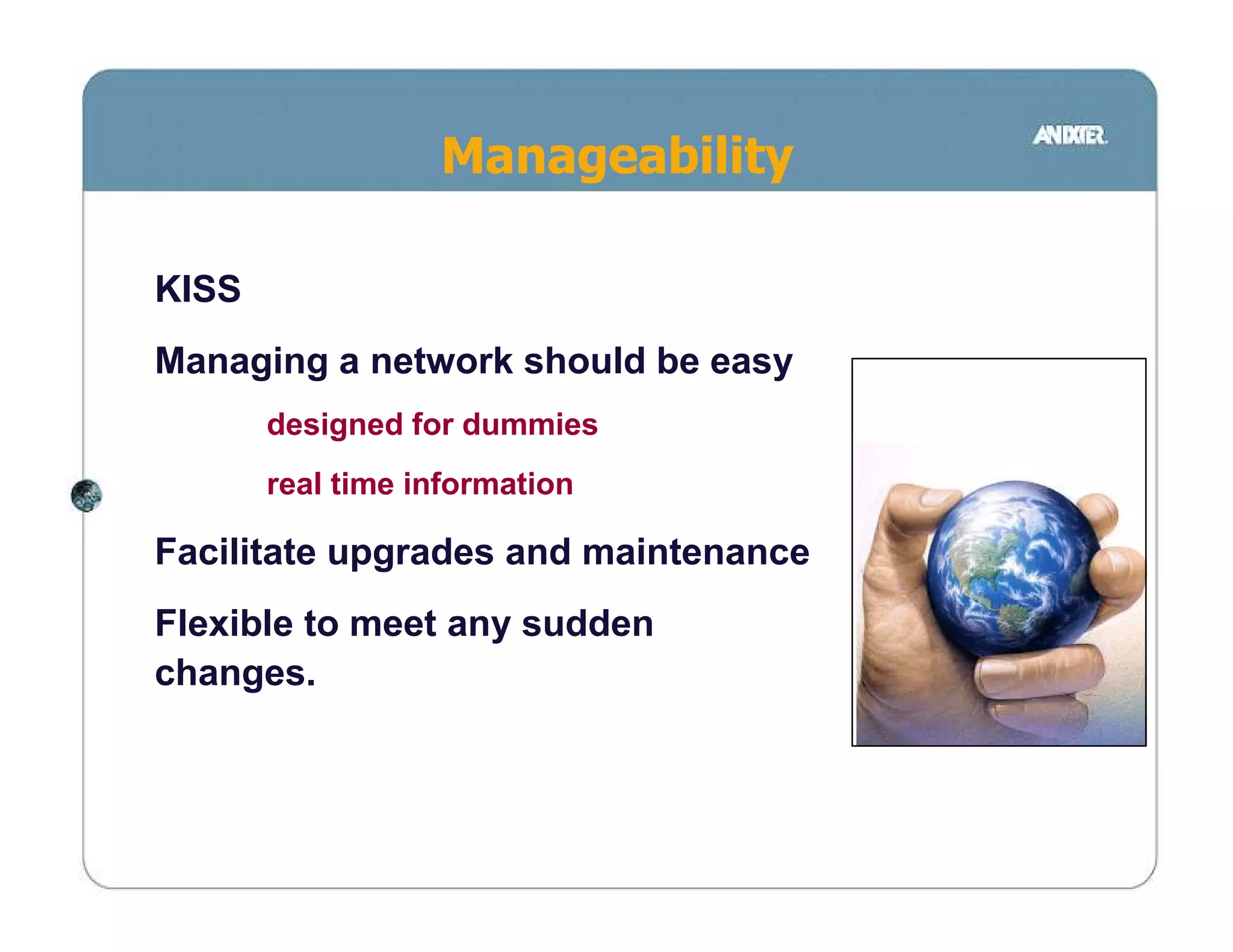
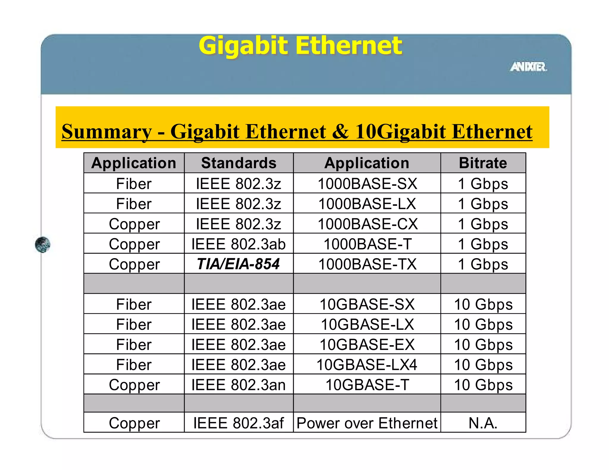
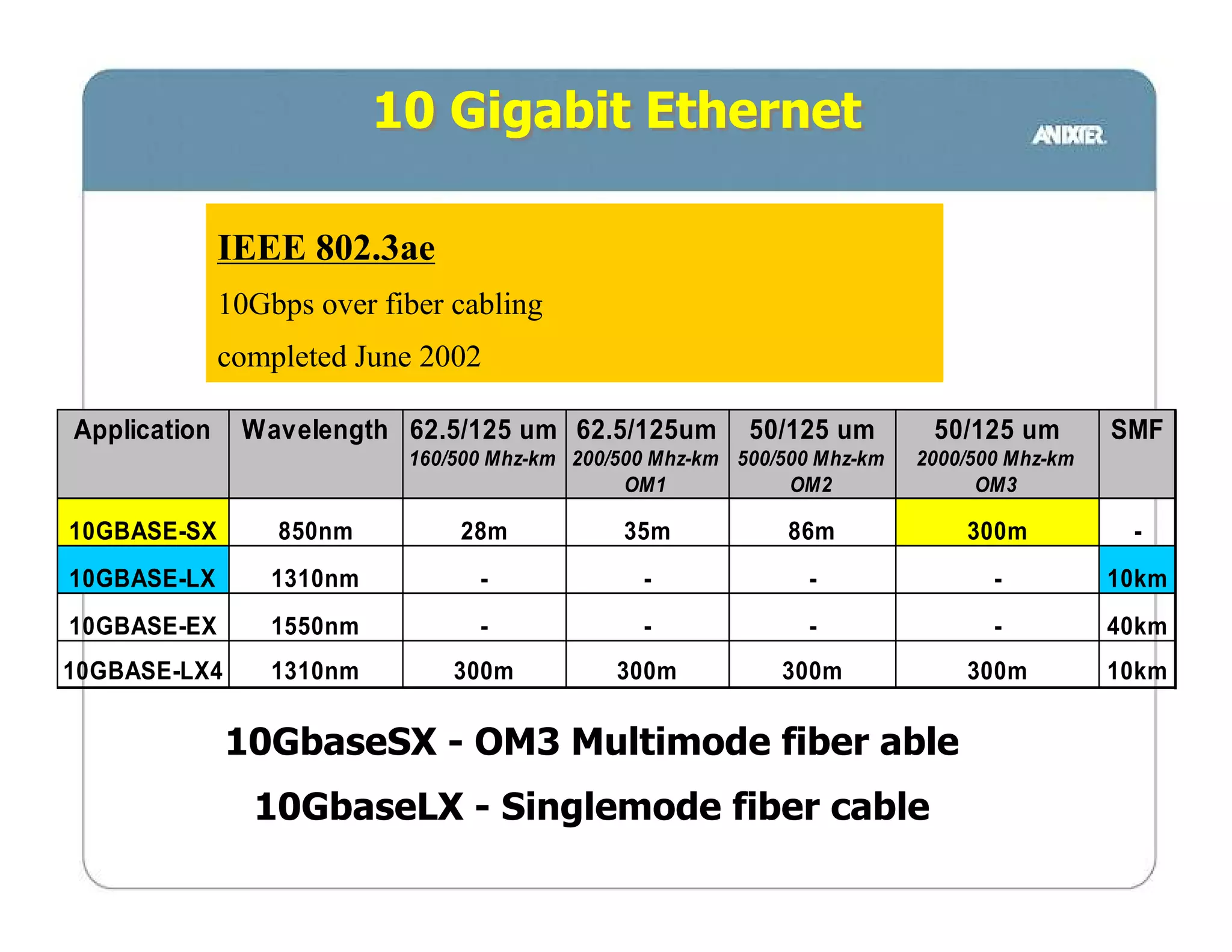
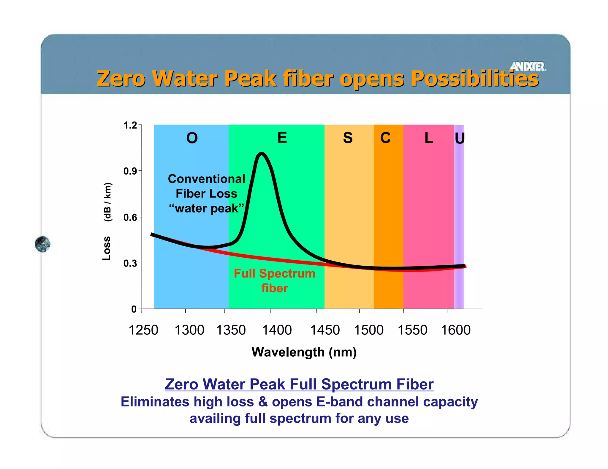
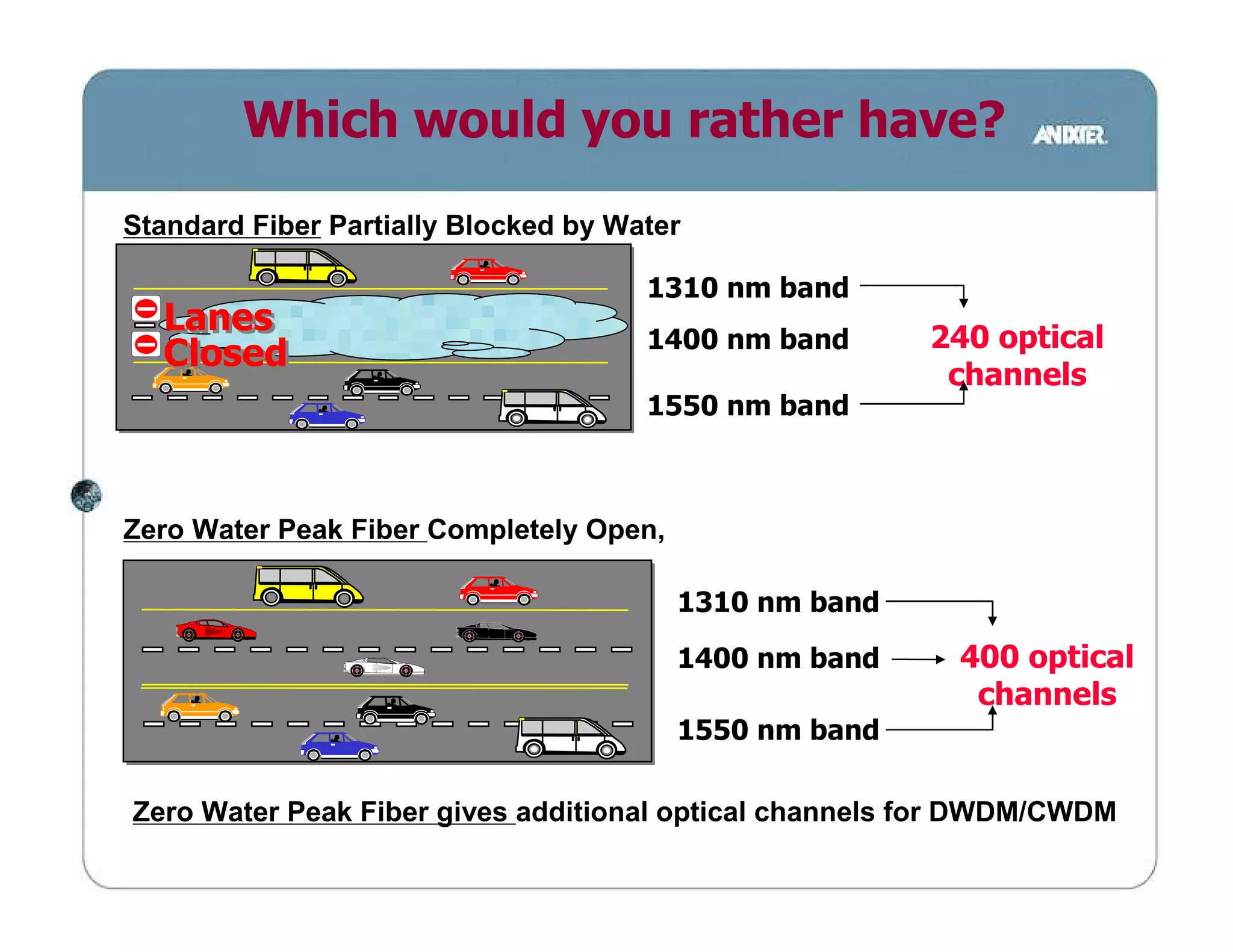
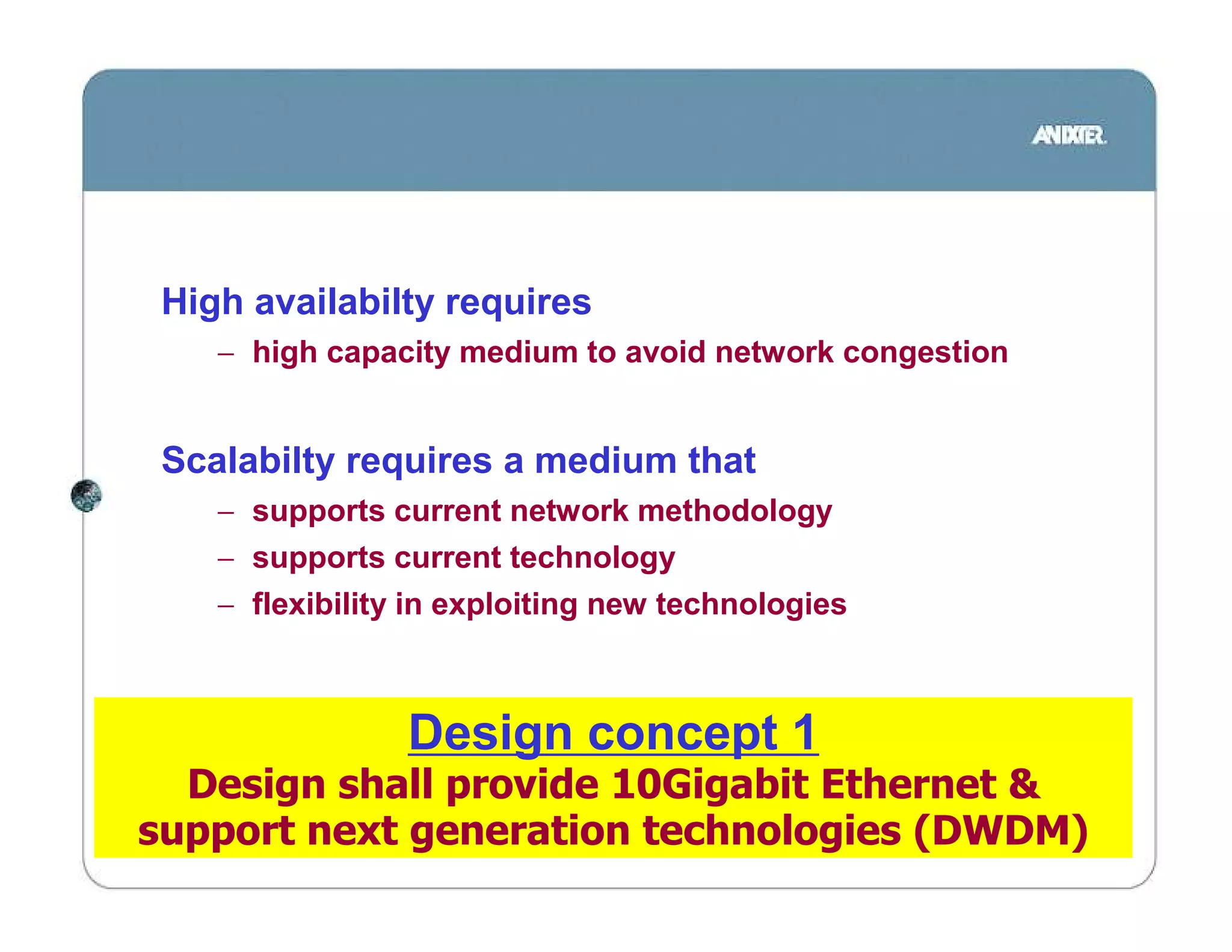
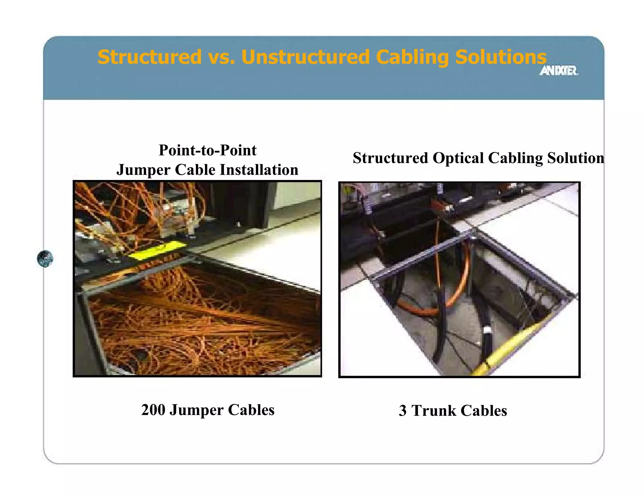
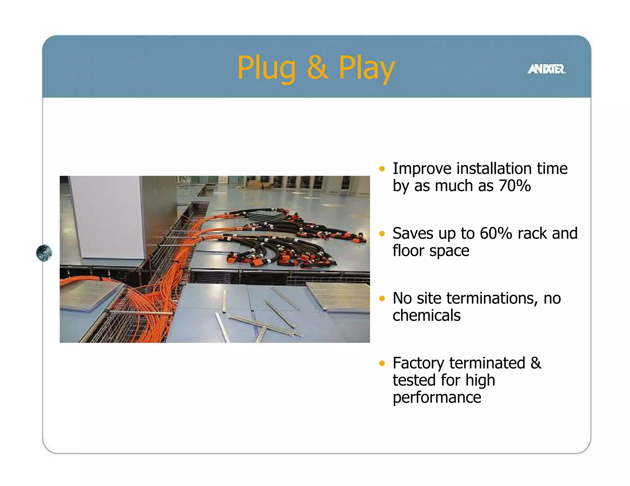
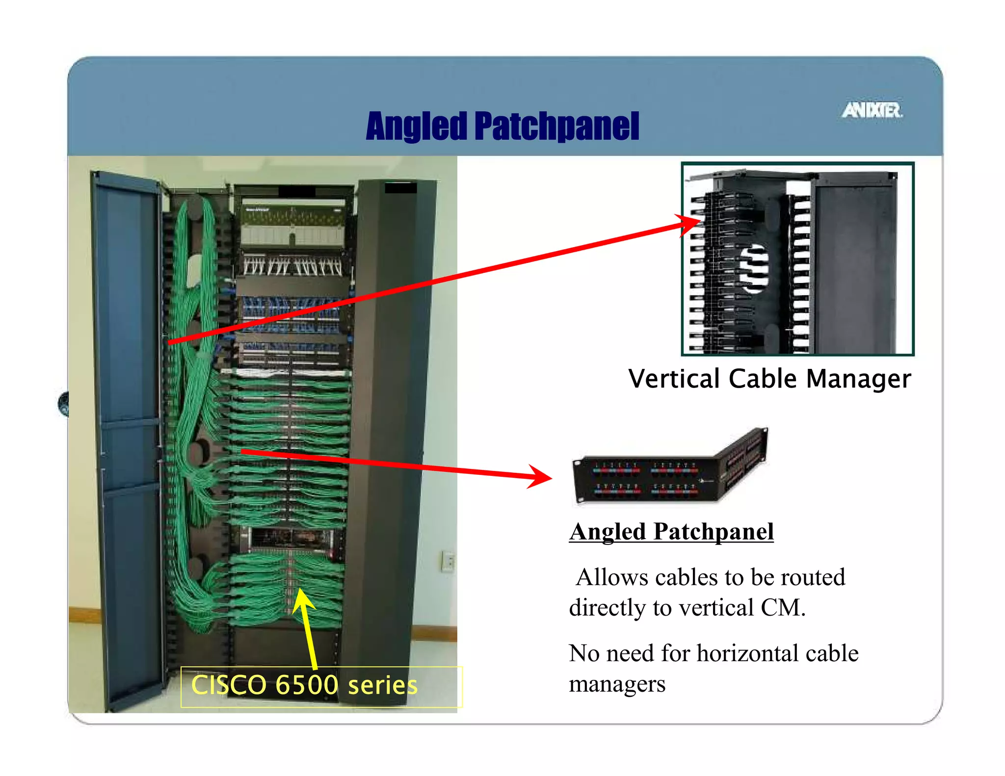
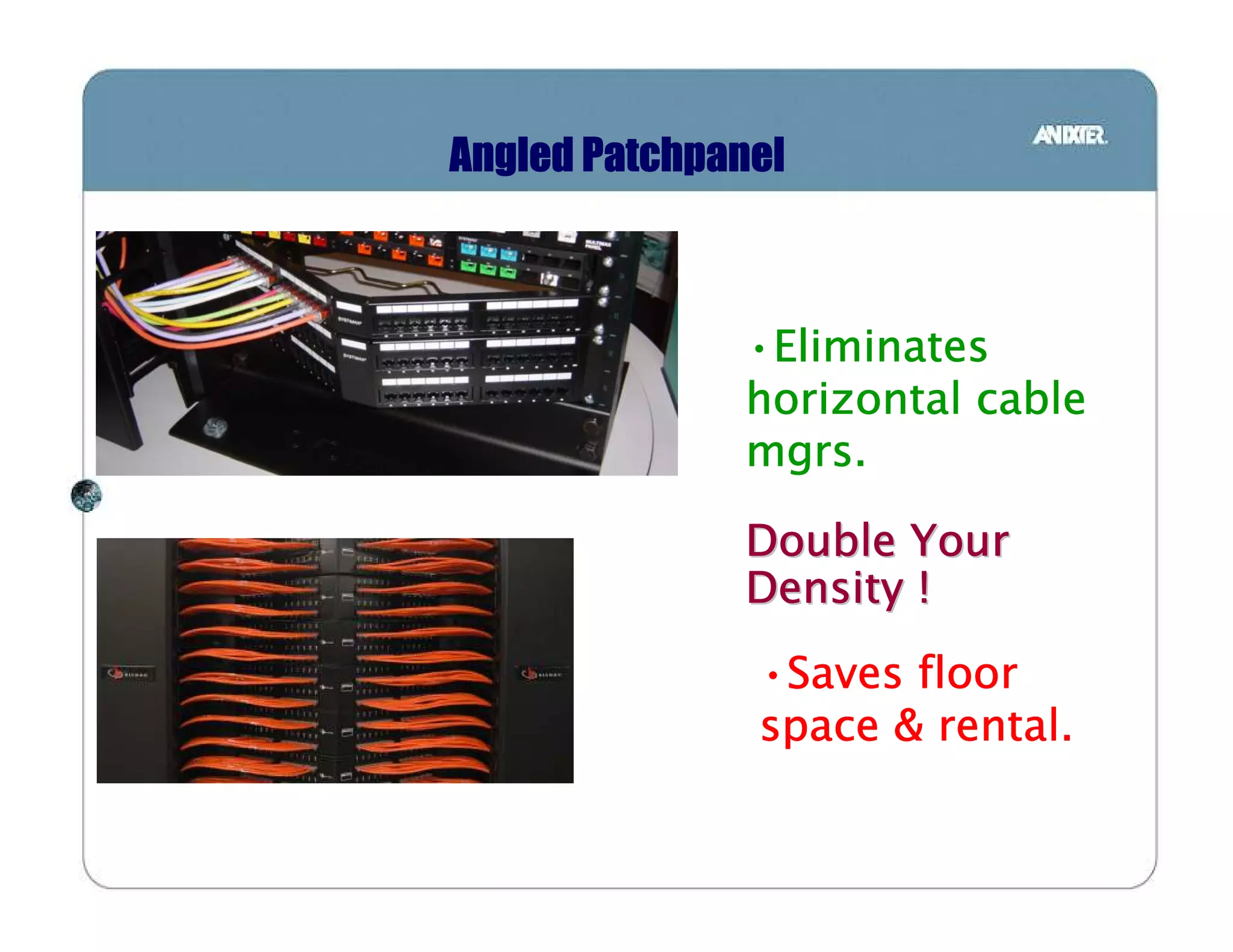
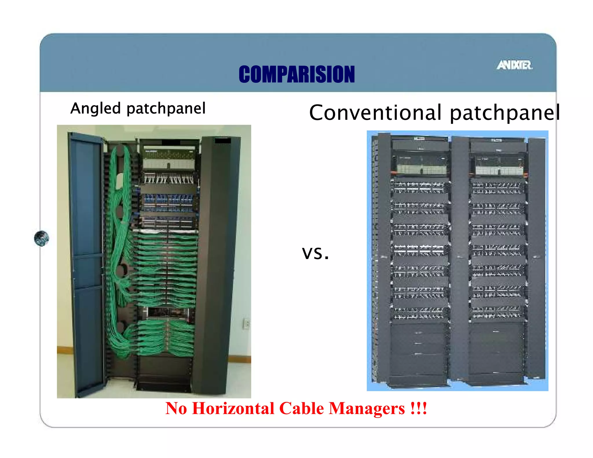
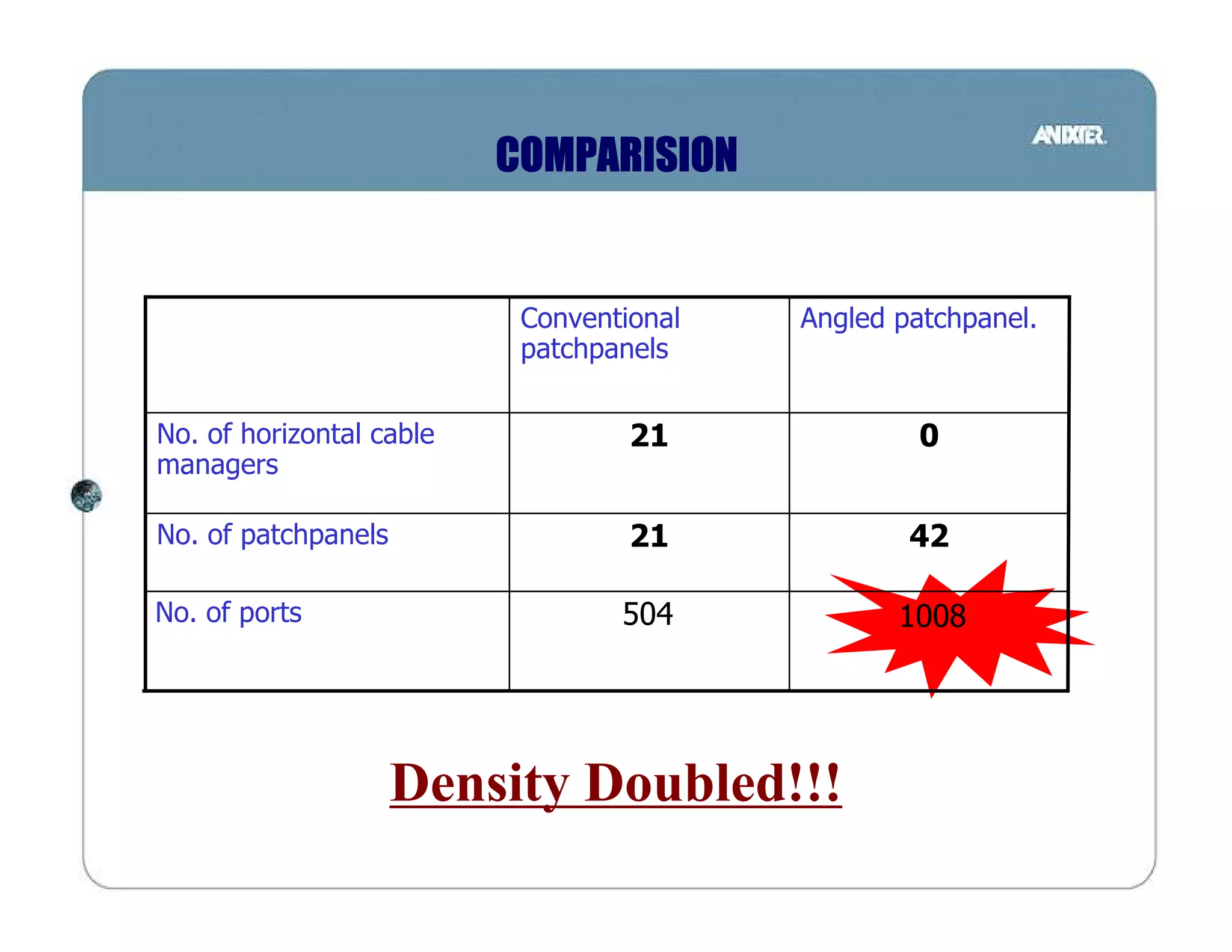
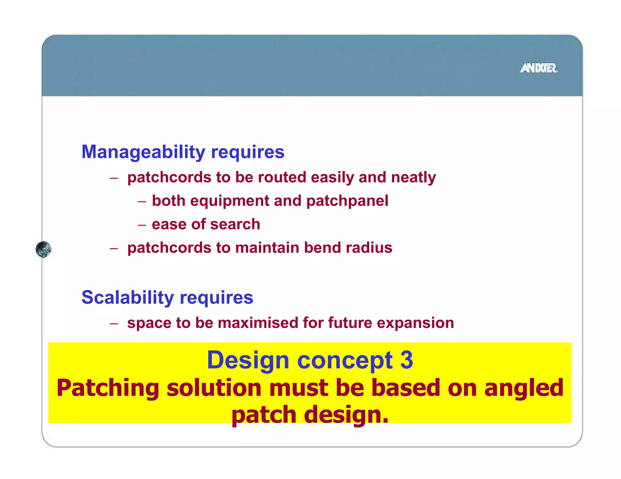
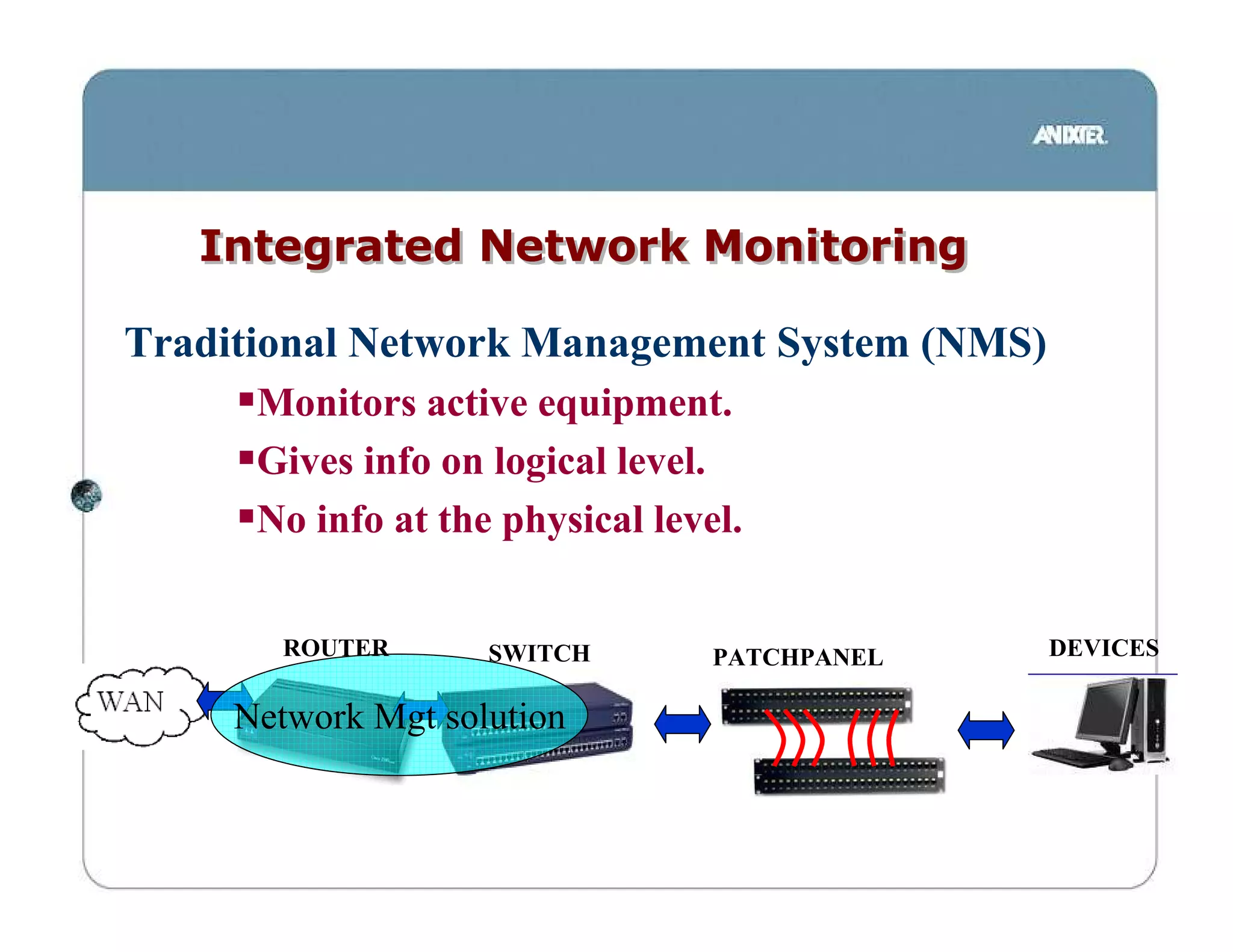
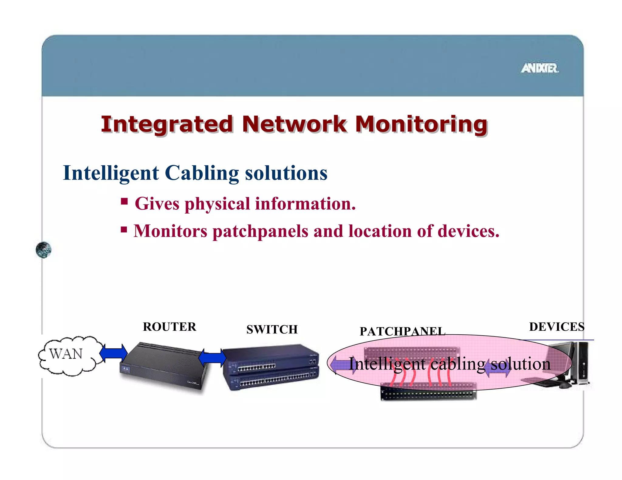
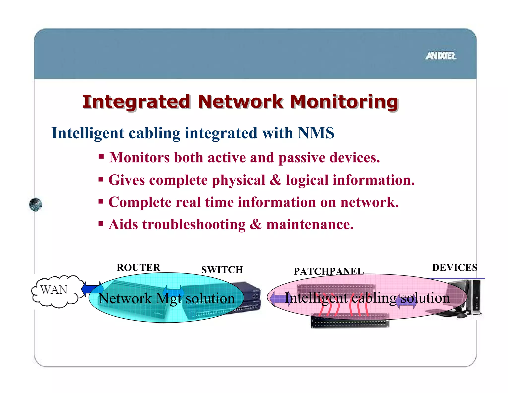
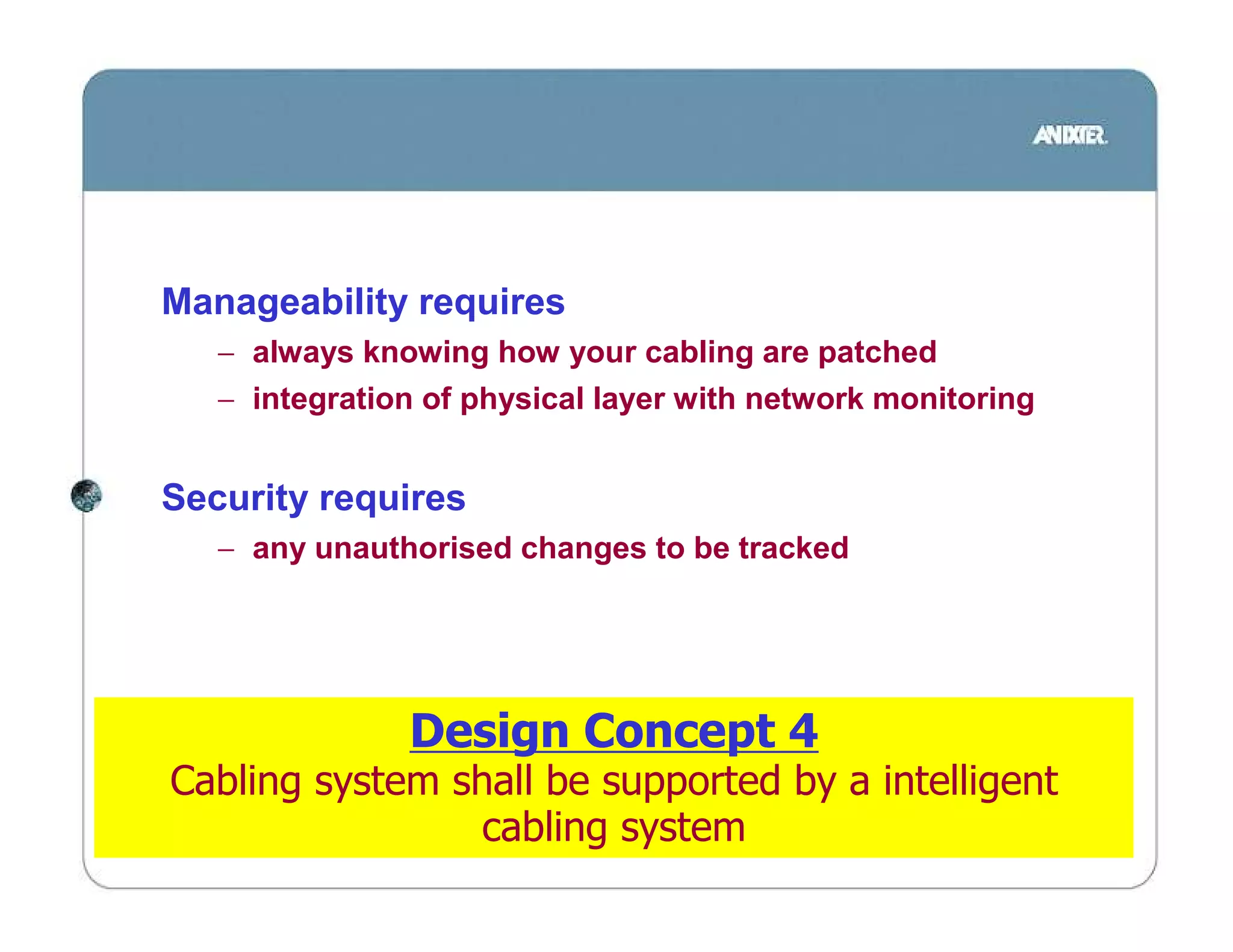
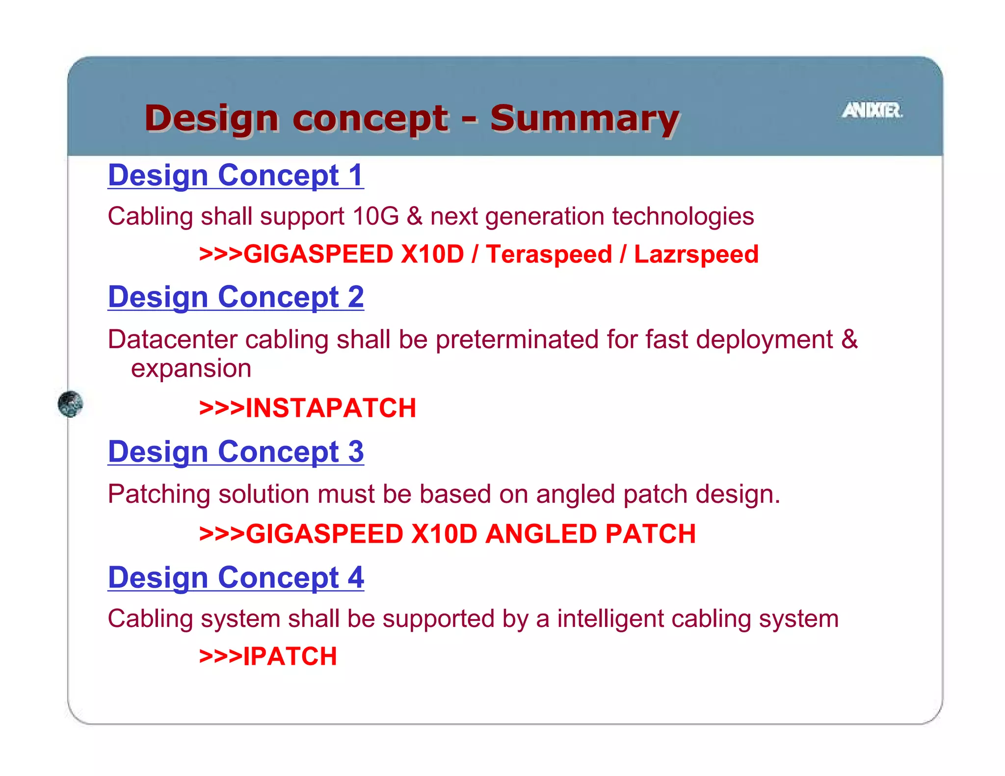
IT infrastructure Design
        Concepts
Network Design Philosophy

              Data center Design Philosophy
           •Security,
           •availability,
           •scalability,
           •manageability.
Security

•Network designed to
      prevents unauthorised access
      identify and isolate illegal actions.

•Usually neglected in the physical
layer.
•Critical to monitor both logical &
physical connectivity.
•Asset management
Availability


Design
                   Issues         solutions
Philosophy


    •Security,
  •availability,
   •scalability,
 •manageability.
Availability
•Networks are designed to minimize the
occurrence of service problems

•Redundancy based design.

•Capacity to be higher than minimum to
cater for
      increased traffic loads
      bandwidth intensive applications

•SlowtimeTM
Network must not only be up but
throughput must be maximised.

•High performance / bandwidth solutions
Flexibility / Scalability


    •Ability to grow with your business
    •System must adapt to ever-
    changing network requirements
    •Scalable deployment of network
    services
       speed of deployment
       optimise existing investment
Manageability

KISS
Managing a network should be easy
       designed for dummies
       real time information

Facilitate upgrades and maintenance
Flexible to meet any sudden
changes.
Current network
 technologies
Gigabit Ethernet


Summary - Gigabit Ethernet & 10Gigabit Ethernet
  Application   Standards       Application      Bitrate
     Fiber     IEEE 802.3z     1000BASE-SX       1 Gbps
     Fiber     IEEE 802.3z     1000BASE-LX       1 Gbps
    Copper     IEEE 802.3z     1000BASE-CX       1 Gbps
    Copper    IEEE 802.3ab      1000BASE-T       1 Gbps
    Copper     TIA/EIA-854     1000BASE-TX       1 Gbps

     Fiber    IEEE   802.3ae   10GBASE-SX        10 Gbps
     Fiber    IEEE   802.3ae    10GBASE-LX       10 Gbps
     Fiber    IEEE   802.3ae   10GBASE-EX        10 Gbps
     Fiber    IEEE   802.3ae   10GBASE-LX4       10 Gbps
    Copper    IEEE   802.3an     10GBASE-T       10 Gbps

    Copper    IEEE 802.3af Power over Ethernet    N.A.
10 Gigabit Ethernet

              IEEE 802.3ae
              10Gbps over fiber cabling
              completed June 2002

Application    Wavelength 62.5/125 um 62.5/125um           50/125 um        50/125 um        SMF
                            160/500 Mhz-km 200/500 Mhz-km 500/500 Mhz-km   2000/500 Mhz-km
                                                OM1            OM2               OM3

10GBASE-SX        850nm         28m            35m             86m             300m           -
10GBASE-LX        1310nm          -              -               -                -          10km
10GBASE-EX        1550nm          -              -               -                -          40km
10GBASE-LX4       1310nm        300m           300m           300m             300m          10km


              10GbaseSX - OM3 Multimode fiber able
                10GbaseLX - Singlemode fiber cable
10 Gigabit Ethernet


 IEEE 802.3an
 10 Gigabit Ethernet on twisted pair cabling
 standard completed in July 2006

Objectives
        •35m over Cat 6 UTP cabling
        •100m over augmented Cat 6 cabling
current cabling may not support 10GBase-T.
    •Existing Cat 6 cabling need to be qualified to TSR 155 / TR24750
    •New cabling standard Cat 6A to be published under EIA/TIA 568b.2-10
Full Spectrum “Zero
 Water peak” Fiber
Normal fiber operating windows
        1.2
                       O               E       S      C   L   U
        0.9
                     Conventional
                      Fiber Loss
              (dB /
              km)
        0.6
              Loss


        0.3


         0
                                    Wavelength (nm)
        1250 1300 1350 1400 1450 1500 1550 1600

Why are there no applications @ 1400nm?

 ANSWER:              HIGH LOSS!!!
                      1350nm to 1450nm (E-band)
                      traditionally no operation due to high loss.
E-band
    Standard Fiber Partially Blocked by Water

                                                1310 nm band
        Lanes
        Closed                                  1400 nm band


                                                1550 nm band


•1280 to 1625nm
•highest loss at 1383nm
•loss caused by hydroxl ions in the glass
•traditional manufacturing process unable to remove these ions.
•Commonly known as “Water Peak”
•Ordinary singlemode fiber (G.652 compliant fiber) suffers from
this problem.
Zero Water Peak Full Spectrum fiber
        Singlemode Fiber


− 9um SINGLEMODE
− G.652.C compliant
− no water peak
− removes Hydroxl ions from fiber
− Increases capacity per Fiber
    − Due to elimination of water peak causing high loss
    − 60% more usable wavelengths
    − Maximizes support for CWDM / DWDM
− Low Cost Future Proofing for Next Generation Equipment
Zero Water Peak fiber opens Possibilities

            1.2
                      O               E         S    C   L   U

            0.9
                    Conventional
(dB / km)


                     Fiber Loss
                    “water peak”
            0.6
Loss


            0.3
                              Full Spectrum
                                   fiber
             0

             1250    1300 1350      1400   1450 1500 1550 1600
                                   Wavelength (nm)

                    Zero Water Peak Full Spectrum Fiber
            Eliminates high loss & opens E-band channel capacity
                      availing full spectrum for any use
Which would you rather have?
Standard Fiber Partially Blocked by Water

                                      1310 nm band
  Lanes                                                 240 optical
                                      1400 nm band
  Closed
                                                         channels
                                      1550 nm band


Zero Water Peak Fiber Completely Open,

                                         1310 nm band
                                         1400 nm band     400 optical
                                                           channels
                                         1550 nm band

Zero Water Peak Fiber gives additional optical channels for DWDM/CWDM
High availabilty requires
    − high capacity medium to avoid network congestion


 Scalabilty requires a medium that
    − supports current network methodology
    − supports current technology
    − flexibility in exploiting new technologies


                 Design concept 1
  Design shall provide 10Gigabit Ethernet &
support next generation technologies (DWDM)
Preterminated cabling
      systems
Structured vs. Unstructured Cabling Solutions


     Point-to-Point          Structured Optical Cabling Solution
 Jumper Cable Installation


    200 Jumper Cables              3 Trunk Cables
Data center considerations


• Fast installation
       •Installer spend less time in data center
       •shorter cut-over
• High Performance
       •minimise down-time
       •Low loss allow for flexibility in design
• Minimise space used
       •Data center high cost due to supporting facilities
• No chemicals
       •confined areas - fumes difficult to disperse
       •prevents accidental fires / damage
Connector Options

  Connectors
  • Modules support wide range of connectors
     – SC, ST, LC

  • Modules connect to trunk
     – MTP connectors.


                                               MTP
                                               connector
SC, ST, LC, MTRJ connectors
Plug & Play


         • Improve installation time
           by as much as 70%

         • Saves up to 60% rack and
           floor space

         • No site terminations, no
           chemicals

         • Factory terminated &
           tested for high
           performance
Scalabilty requires
    − rapid deployment / expansion
    − factory terminated performance


 Manageability requires
    − lower cable counts for easy handling


                Design Concept 2
Datacenter cabling shall be preterminated
    for fast deployment & expansion
Angled Patchpanel
     design
Angled Patchpanel


                              Vertical Cable Manager


                         Angled Patchpanel
                         Allows cables to be routed
                         directly to vertical CM.
                         No need for horizontal cable
CISCO 6500 series        managers
Angled Patchpanel


              •Eliminates
               Eliminates
              horizontal cable
              mgrs.

              Double Your
              Density !
               •Saves floor
                Saves
               space & rental.
COMPARISION
Angled patchpanel           Conventional patchpanel


                           vs.


           No Horizontal Cable Managers !!!
COMPARISION


                           Conventional   Angled patchpanel.
                           patchpanels


No. of horizontal cable            21              0
managers

No. of patchpanels                 21             42

No. of ports                      504            1008


                     Density Doubled!!!
Manageability requires
     − patchcords to be routed easily and neatly
        − both equipment and patchpanel
        − ease of search
     − patchcords to maintain bend radius


  Scalability requires
     − space to be maximised for future expansion

                 Design concept 3
Patching solution must be based on angled
               patch design.
Integrated Network Monitoring

Traditional Network Management System (NMS)
      Monitors active equipment.
      Gives info on logical level.
      No info at the physical level.


       ROUTER       SWITCH        PATCHPANEL   DEVICES

     Network Mgt solution
Integrated Network Monitoring

Intelligent Cabling solutions
       Gives physical information.
       Monitors patchpanels and location of devices.


        ROUTER      SWITCH        PATCHPANEL             DEVICES


                                 Intelligent cabling solution
Integrated Network Monitoring
Intelligent cabling integrated with NMS
       Monitors both active and passive devices.
       Gives complete physical & logical information.
       Complete real time information on network.
       Aids troubleshooting & maintenance.

        ROUTER       SWITCH       PATCHPANEL             DEVICES


      Network Mgt solution       Intelligent cabling solution
Manageability requires
   − always knowing how your cabling are patched
   − integration of physical layer with network monitoring


Security requires
   − any unauthorised changes to be tracked


               Design Concept 4
Cabling system shall be supported by a intelligent
                 cabling system
Design concept - Summary


Design Concept 1
Cabling shall support 10G & next generation technologies
Design Concept 2
Datacenter cabling shall be preterminated for fast deployment &
 expansion
Design Concept 3
Patching solution must be based on angled patch design.
Design Concept 4
Cabling system shall be supported by a intelligent cabling system
Design concept - Summary
Design Concept 1
Cabling shall support 10G & next generation technologies
        >>>GIGASPEED X10D / Teraspeed / Lazrspeed
Design Concept 2
Datacenter cabling shall be preterminated for fast deployment &
 expansion
        >>>INSTAPATCH
Design Concept 3
Patching solution must be based on angled patch design.
        >>>GIGASPEED X10D ANGLED PATCH
Design Concept 4
Cabling system shall be supported by a intelligent cabling system
        >>>IPATCH
•QUESTIONS?
   Jeffrey.lam@anixter.com
       +65 97849870

Microsoft power point it cabling infrastructure design concepts

  • 1.
  • 2.
    Network Design Philosophy Data center Design Philosophy •Security, •availability, •scalability, •manageability.
  • 3.
    Security •Network designed to prevents unauthorised access identify and isolate illegal actions. •Usually neglected in the physical layer. •Critical to monitor both logical & physical connectivity. •Asset management
  • 4.
    Availability Design Issues solutions Philosophy •Security, •availability, •scalability, •manageability.
  • 5.
    Availability •Networks are designedto minimize the occurrence of service problems •Redundancy based design. •Capacity to be higher than minimum to cater for increased traffic loads bandwidth intensive applications •SlowtimeTM Network must not only be up but throughput must be maximised. •High performance / bandwidth solutions
  • 6.
    Flexibility / Scalability •Ability to grow with your business •System must adapt to ever- changing network requirements •Scalable deployment of network services speed of deployment optimise existing investment
  • 7.
    Manageability KISS Managing a networkshould be easy designed for dummies real time information Facilitate upgrades and maintenance Flexible to meet any sudden changes.
  • 8.
  • 9.
    Gigabit Ethernet Summary -Gigabit Ethernet & 10Gigabit Ethernet Application Standards Application Bitrate Fiber IEEE 802.3z 1000BASE-SX 1 Gbps Fiber IEEE 802.3z 1000BASE-LX 1 Gbps Copper IEEE 802.3z 1000BASE-CX 1 Gbps Copper IEEE 802.3ab 1000BASE-T 1 Gbps Copper TIA/EIA-854 1000BASE-TX 1 Gbps Fiber IEEE 802.3ae 10GBASE-SX 10 Gbps Fiber IEEE 802.3ae 10GBASE-LX 10 Gbps Fiber IEEE 802.3ae 10GBASE-EX 10 Gbps Fiber IEEE 802.3ae 10GBASE-LX4 10 Gbps Copper IEEE 802.3an 10GBASE-T 10 Gbps Copper IEEE 802.3af Power over Ethernet N.A.
  • 10.
    10 Gigabit Ethernet IEEE 802.3ae 10Gbps over fiber cabling completed June 2002 Application Wavelength 62.5/125 um 62.5/125um 50/125 um 50/125 um SMF 160/500 Mhz-km 200/500 Mhz-km 500/500 Mhz-km 2000/500 Mhz-km OM1 OM2 OM3 10GBASE-SX 850nm 28m 35m 86m 300m - 10GBASE-LX 1310nm - - - - 10km 10GBASE-EX 1550nm - - - - 40km 10GBASE-LX4 1310nm 300m 300m 300m 300m 10km 10GbaseSX - OM3 Multimode fiber able 10GbaseLX - Singlemode fiber cable
  • 11.
    10 Gigabit Ethernet IEEE 802.3an 10 Gigabit Ethernet on twisted pair cabling standard completed in July 2006 Objectives •35m over Cat 6 UTP cabling •100m over augmented Cat 6 cabling current cabling may not support 10GBase-T. •Existing Cat 6 cabling need to be qualified to TSR 155 / TR24750 •New cabling standard Cat 6A to be published under EIA/TIA 568b.2-10
  • 12.
    Full Spectrum “Zero Water peak” Fiber
  • 13.
    Normal fiber operatingwindows 1.2 O E S C L U 0.9 Conventional Fiber Loss (dB / km) 0.6 Loss 0.3 0 Wavelength (nm) 1250 1300 1350 1400 1450 1500 1550 1600 Why are there no applications @ 1400nm? ANSWER: HIGH LOSS!!! 1350nm to 1450nm (E-band) traditionally no operation due to high loss.
  • 14.
    E-band Standard Fiber Partially Blocked by Water 1310 nm band Lanes Closed 1400 nm band 1550 nm band •1280 to 1625nm •highest loss at 1383nm •loss caused by hydroxl ions in the glass •traditional manufacturing process unable to remove these ions. •Commonly known as “Water Peak” •Ordinary singlemode fiber (G.652 compliant fiber) suffers from this problem.
  • 15.
    Zero Water PeakFull Spectrum fiber Singlemode Fiber − 9um SINGLEMODE − G.652.C compliant − no water peak − removes Hydroxl ions from fiber − Increases capacity per Fiber − Due to elimination of water peak causing high loss − 60% more usable wavelengths − Maximizes support for CWDM / DWDM − Low Cost Future Proofing for Next Generation Equipment
  • 16.
    Zero Water Peakfiber opens Possibilities 1.2 O E S C L U 0.9 Conventional (dB / km) Fiber Loss “water peak” 0.6 Loss 0.3 Full Spectrum fiber 0 1250 1300 1350 1400 1450 1500 1550 1600 Wavelength (nm) Zero Water Peak Full Spectrum Fiber Eliminates high loss & opens E-band channel capacity availing full spectrum for any use
  • 17.
    Which would yourather have? Standard Fiber Partially Blocked by Water 1310 nm band Lanes 240 optical 1400 nm band Closed channels 1550 nm band Zero Water Peak Fiber Completely Open, 1310 nm band 1400 nm band 400 optical channels 1550 nm band Zero Water Peak Fiber gives additional optical channels for DWDM/CWDM
  • 18.
    High availabilty requires − high capacity medium to avoid network congestion Scalabilty requires a medium that − supports current network methodology − supports current technology − flexibility in exploiting new technologies Design concept 1 Design shall provide 10Gigabit Ethernet & support next generation technologies (DWDM)
  • 19.
  • 20.
    Structured vs. UnstructuredCabling Solutions Point-to-Point Structured Optical Cabling Solution Jumper Cable Installation 200 Jumper Cables 3 Trunk Cables
  • 21.
    Data center considerations •Fast installation •Installer spend less time in data center •shorter cut-over • High Performance •minimise down-time •Low loss allow for flexibility in design • Minimise space used •Data center high cost due to supporting facilities • No chemicals •confined areas - fumes difficult to disperse •prevents accidental fires / damage
  • 22.
    Connector Options Connectors • Modules support wide range of connectors – SC, ST, LC • Modules connect to trunk – MTP connectors. MTP connector SC, ST, LC, MTRJ connectors
  • 23.
    Plug & Play • Improve installation time by as much as 70% • Saves up to 60% rack and floor space • No site terminations, no chemicals • Factory terminated & tested for high performance
  • 24.
    Scalabilty requires − rapid deployment / expansion − factory terminated performance Manageability requires − lower cable counts for easy handling Design Concept 2 Datacenter cabling shall be preterminated for fast deployment & expansion
  • 25.
  • 26.
    Angled Patchpanel Vertical Cable Manager Angled Patchpanel Allows cables to be routed directly to vertical CM. No need for horizontal cable CISCO 6500 series managers
  • 27.
    Angled Patchpanel •Eliminates Eliminates horizontal cable mgrs. Double Your Density ! •Saves floor Saves space & rental.
  • 28.
    COMPARISION Angled patchpanel Conventional patchpanel vs. No Horizontal Cable Managers !!!
  • 29.
    COMPARISION Conventional Angled patchpanel. patchpanels No. of horizontal cable 21 0 managers No. of patchpanels 21 42 No. of ports 504 1008 Density Doubled!!!
  • 30.
    Manageability requires − patchcords to be routed easily and neatly − both equipment and patchpanel − ease of search − patchcords to maintain bend radius Scalability requires − space to be maximised for future expansion Design concept 3 Patching solution must be based on angled patch design.
  • 31.
    Integrated Network Monitoring TraditionalNetwork Management System (NMS) Monitors active equipment. Gives info on logical level. No info at the physical level. ROUTER SWITCH PATCHPANEL DEVICES Network Mgt solution
  • 32.
    Integrated Network Monitoring IntelligentCabling solutions Gives physical information. Monitors patchpanels and location of devices. ROUTER SWITCH PATCHPANEL DEVICES Intelligent cabling solution
  • 33.
    Integrated Network Monitoring Intelligentcabling integrated with NMS Monitors both active and passive devices. Gives complete physical & logical information. Complete real time information on network. Aids troubleshooting & maintenance. ROUTER SWITCH PATCHPANEL DEVICES Network Mgt solution Intelligent cabling solution
  • 34.
    Manageability requires − always knowing how your cabling are patched − integration of physical layer with network monitoring Security requires − any unauthorised changes to be tracked Design Concept 4 Cabling system shall be supported by a intelligent cabling system
  • 35.
    Design concept -Summary Design Concept 1 Cabling shall support 10G & next generation technologies Design Concept 2 Datacenter cabling shall be preterminated for fast deployment & expansion Design Concept 3 Patching solution must be based on angled patch design. Design Concept 4 Cabling system shall be supported by a intelligent cabling system
  • 36.
    Design concept -Summary Design Concept 1 Cabling shall support 10G & next generation technologies >>>GIGASPEED X10D / Teraspeed / Lazrspeed Design Concept 2 Datacenter cabling shall be preterminated for fast deployment & expansion >>>INSTAPATCH Design Concept 3 Patching solution must be based on angled patch design. >>>GIGASPEED X10D ANGLED PATCH Design Concept 4 Cabling system shall be supported by a intelligent cabling system >>>IPATCH
  • 37.
    •QUESTIONS? Jeffrey.lam@anixter.com +65 97849870