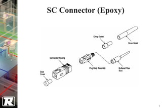
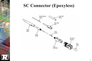
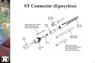
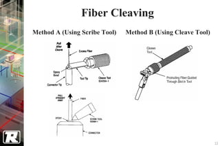
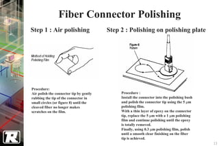
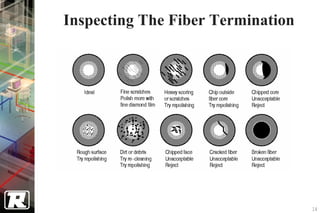
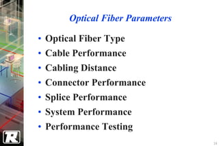
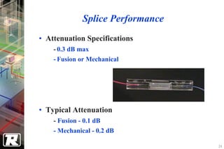
1. The document discusses fiber optic installation including fiber connector types, splicing, mechanical splices, fusion splices, connectors, cleaving, polishing, inspection, cabling systems, parameters, cable types, distances, and testing.
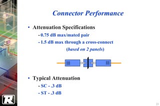
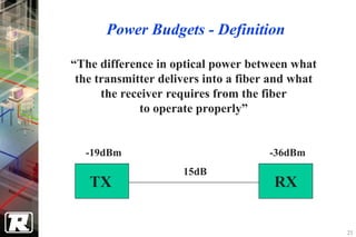
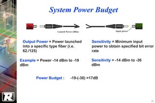
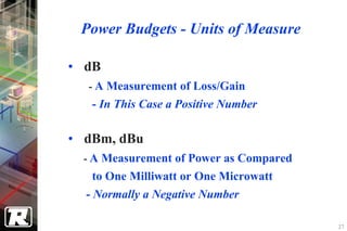
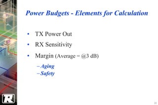
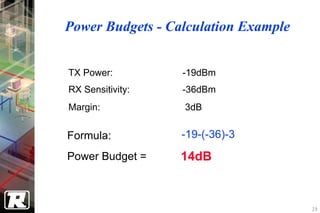
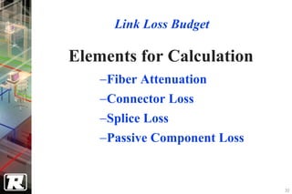
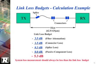
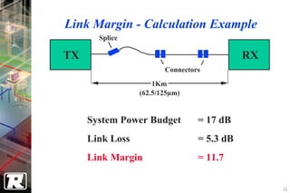
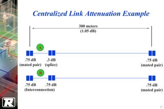
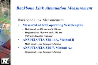
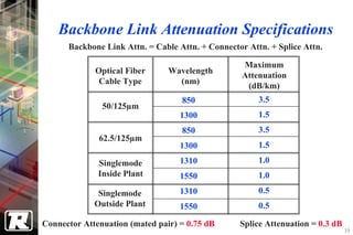
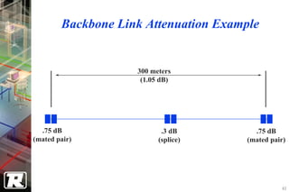
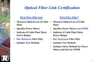
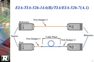
2. Key aspects covered include link loss budgets, power budgets, attenuation specifications for links, certification standards, and troubleshooting faults.
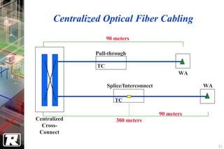
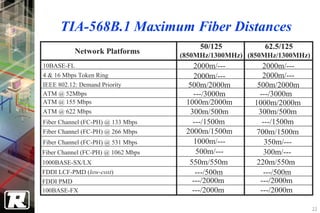
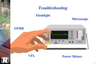
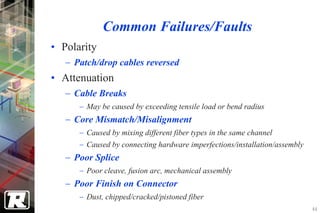
3. Installation and testing of fiber optic cabling must follow industry standards to ensure the link meets power and attenuation budgets and performs as specified.