Downloaded 60 times
![References
• Wikipedia. “Structured Cabling” wikipedia.com [Online].
Available : http://en.wikipedia.org/wiki/Structured_cabling
• Linctionaryt . “TIA/EIA Structured Cabling Standards”
linktionary.com [Online]. Available :
http://www.linktionary.com/t/tia_cabling.html
• Paul Rosenberg (2000, Apr. 1). “The Basics of Structured
Cabling”. EC & M [Online]. Available:
http://ecmweb.com/basics/basics-structured-cabling](https://image.slidesharecdn.com/rdmawmphrzclezebaum7-signature-9dd10432d473180f08edb6c4478e4696f192bb9c60d6fdfbb987671e12616d94-poli-150315124026-conversion-gate01/85/Structure-cabling-technologies-for-networking-18-320.jpg)

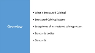
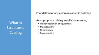
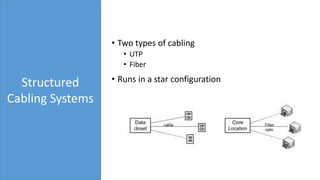
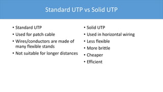
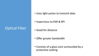
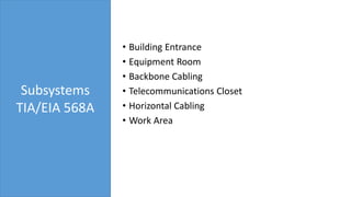
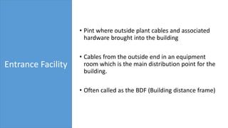
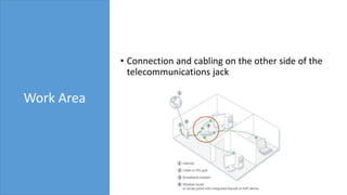
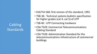
This document provides an overview of structured cabling technologies for networking. It discusses what structured cabling is, the subsystems of a structured cabling system including the entrance facility, equipment room, backbone cabling, telecommunications closet, horizontal cabling, and work area. It also covers the different cabling types, such as UTP and fiber optic cabling. Standards bodies that define cabling standards are mentioned, including EIA/TIA, ANSI, and CSA. Specific standards like EIA/TIA 568 are also discussed.