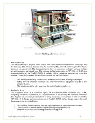
SlideShare a Scribd company logo
White Paper
By: Syed Firas Uddin
September, 2015
Structured Cabling System
White Paper: Structured Cabling System 1
Introduction:
As today’s communication networks become more complex as more users share peripherals, as
more mission critical tasks are accomplished over networks and as the need forfaster access to
information increases,a good foundation for these networks becomesincreasingly important. The first
step towards the adaptability, flexibility and longevity required of today’s networks begins with
structured cabling the foundation of any information system.
A structured cabling system is the wiring network that carries all your data, voice, multimedia,
security, VoIP and Power over Ethernet (PoE) connections throughout a building or campus. It includes
everything from the datacenter to the desktop, including cabling, connecting hardware, equipment,
telecommunication rooms, cable pathways and work areas in an organization. It is a system that
provides a very "structured" approach to the entire cabling system. Structured cabling divides the entire
infrastructure into manageable blocks and then attempts to integrate these blocks to produce the high
performance networks that we have now come to rely on. To an organization, this means investment
protection. In essence, a structured cabling system is the lifeblood of an organization. If done right, it
will serve well for years. If not, an organization’s growth and bottom line can suffer as structured
cabling is the most long lived with an expected life span of 15 to 20 years. It is likely that organizations
will replace network equipment three to four times over the life of the cabling system. An investment in
a high quality cabling system is easily justified in reduced downtime, reduced maintenance, and better
network performance. Structured cabling is widely used in data centers, campuses, offices, apartment
buildings, hospitals, warehouses, manufacturing facilities, etc. and is based on two types of cables,
copper and fiber optics.
This white paper explains a brief overview on the structured cabling system (TIA/EIA-568
cabling standards) and its advantages based on which an organization can benefit allowing them for easy
administration of moves, changes and smooth migration to new network topologies enabling a structured
cabling to last for the life of a network.
Structured Cabling System:
Structured cabling system is governed by a set of standards that specify wiring data centers,
offices and apartment buildings for data or voice communications, using category 5 (CAT 5E) or
category6 cable (CAT 6, 6A) and modular sockets.The reason for having a 'Standard' is to define a
method of connecting all types of vendor’s voice and data equipment, over a cabling system that uses a
common media, common connectors and a common topology. This means that a building can be cabled
for all its communications needs without the planner or architect ever having to know what type of
equipment will be used. Network cabling standards are used internationally and are published by
ISO/IEC, CENELEC and the Telecommunications Industry Association (TIA).The TIA issues the
TIA/EIA-568 and the ISO/IEC issues the ISO/IEC 11801 standard for telecommunications cabling in
commercial premises. Here we will discuss structured cabling system based on TIA/EIA-568 standards.
The structured cabling system consists mainly of six subsections which are defined below as:
White Paper: Structured Cabling System 2
Structured Cabling subsections overview
1. Entrance Facility:
The entrance facility is the point where outside plant cables and associated hardware are brought into
the building. The entrance facilities may be used for public network services, private network
customer services or both. The demarcation point between carrier and customer, and over voltage
protection devices are located here. The entrance facility is designated in TIA/EIA-568-B. Design
recommendations are in TIA/EIA-569-B. It includes cables, connecting hardware and protection
devices. Certain design aspects that shall be considered but not limited to are:
- The entrance facility may also house the backbone links to other buildings in a campus.
- Public network interface equipment and telecommunications equipment may be in the
entrance facility.
- The location should be a dry area, near the vertical backbone pathways.
2. Equipment Room:
The equipment room is a centralized space for telecommunications equipment (e.g., PBX,
computing equipment, video switch, etc.) that serves users in the building. An equipment room may
take the place ofa telecommunications room or it may be separate.Theequipment room is specified in
TIA/EIA-568-B.Design recommendations are in TIA/EIA-569-B. Certain design aspects that shall
be considered but not limited to are:
- Each building should contain at least one equipment room or telecommunications room.
- Consider future expansion when sizing and placing the equipment room.
- The room should have conditioned power and backup power.
White Paper: Structured Cabling System 3
- Take into account any water infiltration issues. Do not locate the room below water level.
- Like the telecommunications room, provide 24h HVAC. Temperature and humidity should
be controlled.
3. Backbone Cabling/Vertical Cabling:
The backbone cabling provides interconnections between telecommunications closets, equipment
rooms and entrance facilities. It consists of the backbone cables, main and intermediate cross
connects, mechanical terminations, and patch cords or jumpers used for cross connection. This
includes vertical connection between floors (risers), cables between an equipment room and building
cable entrance facilities and cables between buildings (inter-building). Backbones may connect
closets within a building orbetween buildings. Backbone cabling is specified in TIA/EIA-568-B.1.
When planning a backbone certain factors must be considered:
- Performance and applications
- Site size and user population
- Redundancy and diverse path routing
- The backbone cabling shall be configured in a star topology. Each horizontal cross-connect
isconnected directly to a main cross-connect or to an intermediate cross-connect, then to a
maincross-connect.
- A total maximum backbone distance of 90m(295ft) is specified for high bandwidth capability
over copper. This distance is for uninterrupted backbone runs.
Cabling types recognized and maximum distances considering main cross connect to horizontal
cross connect are shown below:
Cable Type Backbone Distances
100 ohm UTP (24 or 22 AWG) 800 meters (2625 ft.) Voice*
150 ohm STP 90 meters (295 ft.) Data*
Multimode 62.5/125 μm optical fiber 2,000 meters (6560 ft.)
Single-mode 8.3/125 μm optical fiber 3,000 meters (9840 ft.)
(Backbone distances are application dependent. The maximum distances specified above are based
on voice transmission for UTP and data transmission for STP and fiber.)
4. Horizontal Cabling:
The horizontal cabling consists of the physical media used to connect each outlet in work area to
acloset.It’s called horizontal because the cable typically runs horizontally above the ceiling or below
the floor from the telecommunications room. Various types of cable can be used for horizontal
distribution. Each type has its own performance limitations, size, cost and ease-of-use.It’s specified
in TIA/EIA-568-B.1 and includes horizontal cabling, telecommunications outlets,
telecommunications connectors, cross-connects, patch cords and a consolidation point (if any).When
planning a horizontal cabling certain factors must be considered:
- It should be easy to relocate users and equipmentwithout changing the cable or disrupting users.
Cable shall run to all areas of the building, even if they’revacant for cases of future expansions.
- The current applications shall be considered while planning for more bandwidth
intensiveapplications in the future.
White Paper: Structured Cabling System 4
- Any areas of high EMI such as near elevators, motors, and other equipment should be taken into
account.
- The horizontal cabling shall be configured in a star topology, each work area outlet is connected to a
horizontal cross-connect in a telecommunications closet.
Cabling types recognized and maximum horizontal distancesinvolved in horizontal cabling are
shown below:
Cable Type
4-pair, 100-ohm UTP or ScTP cable (24 AWG,
solid conductors)
2-fiber (or more) 50- and 62.5-micron
fiber optic cable
Cable Area Type Horizontal Distance
Horizontal run( telecommunications outlet to the
horizontalcross-connect)
90 meters (295.3 ft.)
Work area patch cord 5 meters (16.4 ft.).
Total of work area and cross connect patch cords,
equipment cables, jumpers, etc.
10 meters (32.8 ft.)
5. Telecommunications Closet/Room:
The telecommunications closet is where the horizontal distribution cables are terminated. All
recognized types of horizontal cabling are terminated on compatible connecting hardware. Similarly,
recognized backbone cables are also terminated in thecloset. Cross connection is done with jumpers
or patch cords to provide flexible connectivityfor extending various services to users at the
telecommunications outlets.It includes intermediate cross connects, main cross connects, patch cords
and all connecting equipment. The telecommunications closet can also houseauxiliary equipment
such as a PBX, securityequipment, etc.The telecommunications closet is addressed in
TIA/EIA-568-B.1. When planning a telecommunication closet certain factors must be considered:
- Depending on the size of the floor area, it should have at least one telecommunicationsroom
per floor. The recommendation is one telecom closet per 10 sq.m (100 ft.).
- If the floor area is greater than 1000 sq.m (10,763 ft.), or if the distance to the work
areaexceeds 300 feet, there should be additional telecommunication rooms per floor.
- Do not share the telecommunications roomwith electrical equipment.
6. Work Area:
The work area consists of all the components between thetelecommunications outlet and the user’s
workstation equipment.This covers telecommunications outlets, includingwall plates, faceplates,
surface-mount boxes, etc. Also included are patch cables, adapters, connectors, and modularjacks.
Workstation equipment includes PCs, telephones,printers, etc. although they aren’t included inthe
standard.There area few specific recommendations in TIA/EIA-568-B.1:
- A minimum of two telecommunicationsoutlets should be installed in each work area.
White Paper: Structured Cabling System 5
- The 4-pair UTP patch cable from thetelecommunications outlet to the workstationequipment
should be no more than 5 meters(16.4 ft.).
- An electrical outlet should be installed within3 feet (9.1 m) and at the same height.
- Run an independent pathway to control centers,reception areas, and other high-activity
spaces.
- UTP wiring should follow the two approved pinning methods of T568Aand T568B.
The above system makes structured cabling organized providing a better network infrastructure which
can run multiple diverse systems for an organization with a single easy-to-manage network that lowers
both installation and OpEx costs.
Structured Cabling Advantages:
- Consistency – A structured cabling systems means the same cabling systems for Data, voiceand
video.
- Support for multi-vendor equipment – A standard-based cable system will supportapplications and
hardware even with mix & match vendors.
- Simplify moves/adds/changes – Structured cabling systems can support any changes withinthe
systems.
- Simplify troubleshooting – With structured cabling systems, problems are less likely to down the
entire network, easier to isolate and easier to fix.
- Support for future applications – Structured cabling system supports future applications like
multimedia, video conferencing etc. with little or no upgrade pain.
- Reduces cabling bulk and congestion – An organized and planned infrastructure allows for the use of
smaller diameter trunk cabling and cleaner cable management.
- Allows time savings – The network cables and ports tracing becomes a much easier job with a
structured cabling system in larger networks.
A structured approach in cabling helps reduce maintenance costs too. Structured cabling system is
the norm for small, medium and large networks.
Market Outlook:
Saudi Arabia is the largest ICT market by far in the Middle East. For example, the Saudi Arabian
telecommunications and information technology industries represent over 55% and 51% of the total
Middle East markets, respectively. Yet, while many of the world’s ICT markets are maturing, the Saudi
Arabian market remains substantially under developed by global standards and remains on a rapid
White Paper: Structured Cabling System 6
growth trajectory. The size of the Saudi Arabian ICT market provides excellent operational scale. As the
Saudi society is young and growing rapidly, its consumer market is weighted heavily towards
technologically literate people. Saudi Arabia's unique access to energy makes it an attractive location for
a range of activities across the ICT value chain. For example, ICT enabled services providers (such as
data centers) will be able to utilize Saudi Arabia’s unique access to low-cost power and state of the art
communications infrastructure to efficiently service global customers. Equipment and component
production are also highly energy intensive and require significant use of petroleum derivatives such as
chemicals and plastics. These advantages in Saudi Arabian market translate into considerable cost
savings for hardware manufacturing and assembly activities for vendors.
Widespread presence of large scale data centers, campuses, offices, apartment buildings, hospitals,
warehouses, manufacturing facilities, etc. across Saudi Arabian landscape with many global and local
organizations ramping up their operations and foot print in the region proves to be a viable market for
structured cabling systems.
Conclusion:
Many companies are investing huge amounts of money in the latest technology to increase the
speed and capacity of their communications systems in order to gain the greatest competitive
advantages. Structured cabling allows businesses to build a proper foundation for their communication
needs to last well ahead meeting the future demands. However, the ability to run any application, to any
work area, at any time comes only with the proper planning and installation of a high performance
structured cabling system.
There are number of technologies available as well as standards to follow. The implementation
of a proper standardized structured cabling system will ensure a systematic infrastructure to an
organizations network. All these must be understood and put together with intelligence. A properly
planned and installed system will allow companies to spend their time, attention and scarce capital
resources in other areas for years. The ultimate goal is to run anything, anywhere, at any time without
any hassle with a structured approach for an organizations valuable network.

More Related Content

What's hot

Passive infrastructure of FTTH networks: an overview
Passive infrastructure of FTTH networks: an overviewPassive infrastructure of FTTH networks: an overview
Passive infrastructure of FTTH networks: an overview
Luc De Heyn
 
GPON-FTTx Training
GPON-FTTx TrainingGPON-FTTx Training
GPON-FTTx Training
Azhar Khuwaja
 
Wireless network
Wireless networkWireless network
Wireless network
mattglover0
 
3 Basic Principal Of Fo Installation
3 Basic Principal Of Fo Installation3 Basic Principal Of Fo Installation
3 Basic Principal Of Fo Installation
Mrirfan
 
Structure cabling a basic approach
Structure cabling a basic approachStructure cabling a basic approach
Structure cabling a basic approach
dhaneshkhurana016
 
FTTH
FTTHFTTH
BLUETOOTH TECHNOLOGY
BLUETOOTH TECHNOLOGYBLUETOOTH TECHNOLOGY
BLUETOOTH TECHNOLOGY
AJAL A J
 
Types of Ethernet Cable
Types of Ethernet CableTypes of Ethernet Cable
Types of Ethernet Cable
Joanalyn Vidal
 
Fibre optic FTTH FTTX network design, engineering and planning solutions,
Fibre optic FTTH FTTX network design, engineering and planning solutions,Fibre optic FTTH FTTX network design, engineering and planning solutions,
Fibre optic FTTH FTTX network design, engineering and planning solutions,
van den Dool Dick
 
Structured Cabling Technologies
Structured Cabling TechnologiesStructured Cabling Technologies
Structured Cabling Technologies
Chamin Nalinda Loku Gam Hewage
 
Cabling
Cabling Cabling
Cabling
Ah Fawad Saiq
 
VOIP BASIC
VOIP BASICVOIP BASIC
VOIP BASIC
dhara patel
 
MELJUN CORTES networking structured_cabling
MELJUN CORTES networking structured_cablingMELJUN CORTES networking structured_cabling
MELJUN CORTES networking structured_cabling
MELJUN CORTES
 
Design and Simulation WDM
Design and Simulation WDMDesign and Simulation WDM
Design and Simulation WDMMuzahidul Islam
 
Basic Campus Network Design - Network Cabling System
Basic Campus Network Design - Network Cabling SystemBasic Campus Network Design - Network Cabling System
Basic Campus Network Design - Network Cabling System
Md. Abdul Awal
 
FTTH Basics & Network Design
FTTH Basics & Network DesignFTTH Basics & Network Design
FTTH Basics & Network Design
John Lawrence
 
network Switch
 network Switch network Switch
network Switch
zeeshan hanif
 
Networking Basics
Networking BasicsNetworking Basics
Networking Basics
Mohd. ShahNawab
 

What's hot (20)

Passive infrastructure of FTTH networks: an overview
Passive infrastructure of FTTH networks: an overviewPassive infrastructure of FTTH networks: an overview
Passive infrastructure of FTTH networks: an overview
 
GPON-FTTx Training
GPON-FTTx TrainingGPON-FTTx Training
GPON-FTTx Training
 
Wireless network
Wireless networkWireless network
Wireless network
 
3 Basic Principal Of Fo Installation
3 Basic Principal Of Fo Installation3 Basic Principal Of Fo Installation
3 Basic Principal Of Fo Installation
 
Structure cabling a basic approach
Structure cabling a basic approachStructure cabling a basic approach
Structure cabling a basic approach
 
Network Devices
Network DevicesNetwork Devices
Network Devices
 
FTTH
FTTHFTTH
FTTH
 
BLUETOOTH TECHNOLOGY
BLUETOOTH TECHNOLOGYBLUETOOTH TECHNOLOGY
BLUETOOTH TECHNOLOGY
 
Types of Ethernet Cable
Types of Ethernet CableTypes of Ethernet Cable
Types of Ethernet Cable
 
Fibre optic FTTH FTTX network design, engineering and planning solutions,
Fibre optic FTTH FTTX network design, engineering and planning solutions,Fibre optic FTTH FTTX network design, engineering and planning solutions,
Fibre optic FTTH FTTX network design, engineering and planning solutions,
 
Structured Cabling Technologies
Structured Cabling TechnologiesStructured Cabling Technologies
Structured Cabling Technologies
 
Cabling
Cabling Cabling
Cabling
 
VOIP BASIC
VOIP BASICVOIP BASIC
VOIP BASIC
 
MELJUN CORTES networking structured_cabling
MELJUN CORTES networking structured_cablingMELJUN CORTES networking structured_cabling
MELJUN CORTES networking structured_cabling
 
Design and Simulation WDM
Design and Simulation WDMDesign and Simulation WDM
Design and Simulation WDM
 
Basic Campus Network Design - Network Cabling System
Basic Campus Network Design - Network Cabling SystemBasic Campus Network Design - Network Cabling System
Basic Campus Network Design - Network Cabling System
 
FTTH Basics & Network Design
FTTH Basics & Network DesignFTTH Basics & Network Design
FTTH Basics & Network Design
 
network Switch
 network Switch network Switch
network Switch
 
Networking Basics
Networking BasicsNetworking Basics
Networking Basics
 
WiFi Technology & IEEE
WiFi Technology & IEEEWiFi Technology & IEEE
WiFi Technology & IEEE
 

Similar to Structured Cabling Solution - White Paper

structured cabling.pdf
structured cabling.pdfstructured cabling.pdf
structured cabling.pdf
sync_shaide
 
Bs assignment-final
Bs assignment-finalBs assignment-final
Bs assignment-final
khaikeat16
 
Building Services Assignment
Building Services AssignmentBuilding Services Assignment
Building Services Assignment
Erik Ong
 
Building Services Assignment
Building Services AssignmentBuilding Services Assignment
Building Services Assignment
Erik Ong
 
Bs assignment sem2
Bs assignment sem2Bs assignment sem2
Bs assignment sem2
tianji96
 
Choosing the Right Horzontal Cabling System for Healthcare - ROW
Choosing the Right Horzontal Cabling System for Healthcare - ROWChoosing the Right Horzontal Cabling System for Healthcare - ROW
Choosing the Right Horzontal Cabling System for Healthcare - ROWsamuelhuber
 
Telecommunication Services for High Rise Buildings
Telecommunication Services for High Rise BuildingsTelecommunication Services for High Rise Buildings
Telecommunication Services for High Rise Buildings
Pang Shuen
 
BSNL training report
BSNL training reportBSNL training report
BSNL training report
Shubham Singh
 
Bsnl training report
Bsnl training reportBsnl training report
Bsnl training report
Shubham Singh
 
Bsnl
BsnlBsnl
Nt1310 Unit 8 Network Components
Nt1310 Unit 8 Network ComponentsNt1310 Unit 8 Network Components
Nt1310 Unit 8 Network Components
Lisa Williams
 
Bsnl best ppt
Bsnl best pptBsnl best ppt
Bsnl best ppt
rajat pundir
 
Communication & information security final
Communication & information security finalCommunication & information security final
Communication & information security finalneerajchor
 
BVH Network Technology Presentation
BVH   Network Technology PresentationBVH   Network Technology Presentation
BVH Network Technology Presentation
TomMcNamara
 
PCN InterMax IX1610-P Product Brochure rev 1-0 (1)
PCN InterMax IX1610-P Product Brochure rev 1-0 (1)PCN InterMax IX1610-P Product Brochure rev 1-0 (1)
PCN InterMax IX1610-P Product Brochure rev 1-0 (1)Robert Rivenbark
 
Network Technology Presentation Bvh V01
Network Technology Presentation   Bvh V01Network Technology Presentation   Bvh V01
Network Technology Presentation Bvh V01
TomMcNamara
 
BSNL Industrial Training ppt 2014.
BSNL Industrial Training ppt 2014.BSNL Industrial Training ppt 2014.
BSNL Industrial Training ppt 2014.
Shubham Singh
 

Similar to Structured Cabling Solution - White Paper (20)

structured cabling.pdf
structured cabling.pdfstructured cabling.pdf
structured cabling.pdf
 
Bs assignment-final
Bs assignment-finalBs assignment-final
Bs assignment-final
 
Building Services Assignment
Building Services AssignmentBuilding Services Assignment
Building Services Assignment
 
Building Services Assignment
Building Services AssignmentBuilding Services Assignment
Building Services Assignment
 
Bs assignment sem2
Bs assignment sem2Bs assignment sem2
Bs assignment sem2
 
Choosing the Right Horzontal Cabling System for Healthcare - ROW
Choosing the Right Horzontal Cabling System for Healthcare - ROWChoosing the Right Horzontal Cabling System for Healthcare - ROW
Choosing the Right Horzontal Cabling System for Healthcare - ROW
 
Telecommunication Services for High Rise Buildings
Telecommunication Services for High Rise BuildingsTelecommunication Services for High Rise Buildings
Telecommunication Services for High Rise Buildings
 
Chapter10
Chapter10Chapter10
Chapter10
 
BSNL training report
BSNL training reportBSNL training report
BSNL training report
 
Bsnl training report
Bsnl training reportBsnl training report
Bsnl training report
 
Bsnl
BsnlBsnl
Bsnl
 
Nt1310 Unit 8 Network Components
Nt1310 Unit 8 Network ComponentsNt1310 Unit 8 Network Components
Nt1310 Unit 8 Network Components
 
Bsnl best ppt
Bsnl best pptBsnl best ppt
Bsnl best ppt
 
Communication & information security final
Communication & information security finalCommunication & information security final
Communication & information security final
 
BVH Network Technology Presentation
BVH   Network Technology PresentationBVH   Network Technology Presentation
BVH Network Technology Presentation
 
guidebook for designers
guidebook for designersguidebook for designers
guidebook for designers
 
PCN InterMax IX1610-P Product Brochure rev 1-0 (1)
PCN InterMax IX1610-P Product Brochure rev 1-0 (1)PCN InterMax IX1610-P Product Brochure rev 1-0 (1)
PCN InterMax IX1610-P Product Brochure rev 1-0 (1)
 
Network Technology Presentation Bvh V01
Network Technology Presentation   Bvh V01Network Technology Presentation   Bvh V01
Network Technology Presentation Bvh V01
 
BSNL Industrial Training ppt 2014.
BSNL Industrial Training ppt 2014.BSNL Industrial Training ppt 2014.
BSNL Industrial Training ppt 2014.
 
compo 131_banalnal
compo 131_banalnalcompo 131_banalnal
compo 131_banalnal
 

Recently uploaded

Neuro-symbolic is not enough, we need neuro-*semantic*
Neuro-symbolic is not enough, we need neuro-*semantic*Neuro-symbolic is not enough, we need neuro-*semantic*
Neuro-symbolic is not enough, we need neuro-*semantic*
Frank van Harmelen
 
PCI PIN Basics Webinar from the Controlcase Team
PCI PIN Basics Webinar from the Controlcase TeamPCI PIN Basics Webinar from the Controlcase Team
PCI PIN Basics Webinar from the Controlcase Team
ControlCase
 
FIDO Alliance Osaka Seminar: Passkeys and the Road Ahead.pdf
FIDO Alliance Osaka Seminar: Passkeys and the Road Ahead.pdfFIDO Alliance Osaka Seminar: Passkeys and the Road Ahead.pdf
FIDO Alliance Osaka Seminar: Passkeys and the Road Ahead.pdf
FIDO Alliance
 
Connector Corner: Automate dynamic content and events by pushing a button
Connector Corner: Automate dynamic content and events by pushing a buttonConnector Corner: Automate dynamic content and events by pushing a button
Connector Corner: Automate dynamic content and events by pushing a button
DianaGray10
 
From Daily Decisions to Bottom Line: Connecting Product Work to Revenue by VP...
From Daily Decisions to Bottom Line: Connecting Product Work to Revenue by VP...From Daily Decisions to Bottom Line: Connecting Product Work to Revenue by VP...
From Daily Decisions to Bottom Line: Connecting Product Work to Revenue by VP...
Product School
 
UiPath Test Automation using UiPath Test Suite series, part 3
UiPath Test Automation using UiPath Test Suite series, part 3UiPath Test Automation using UiPath Test Suite series, part 3
UiPath Test Automation using UiPath Test Suite series, part 3
DianaGray10
 
Epistemic Interaction - tuning interfaces to provide information for AI support
Epistemic Interaction - tuning interfaces to provide information for AI supportEpistemic Interaction - tuning interfaces to provide information for AI support
Epistemic Interaction - tuning interfaces to provide information for AI support
Alan Dix
 
Accelerate your Kubernetes clusters with Varnish Caching
Accelerate your Kubernetes clusters with Varnish CachingAccelerate your Kubernetes clusters with Varnish Caching
Accelerate your Kubernetes clusters with Varnish Caching
Thijs Feryn
 
Kubernetes & AI - Beauty and the Beast !?! @KCD Istanbul 2024
Kubernetes & AI - Beauty and the Beast !?! @KCD Istanbul 2024Kubernetes & AI - Beauty and the Beast !?! @KCD Istanbul 2024
Kubernetes & AI - Beauty and the Beast !?! @KCD Istanbul 2024
Tobias Schneck
 
From Siloed Products to Connected Ecosystem: Building a Sustainable and Scala...
From Siloed Products to Connected Ecosystem: Building a Sustainable and Scala...From Siloed Products to Connected Ecosystem: Building a Sustainable and Scala...
From Siloed Products to Connected Ecosystem: Building a Sustainable and Scala...
Product School
 
Bits & Pixels using AI for Good.........
Bits & Pixels using AI for Good.........Bits & Pixels using AI for Good.........
Bits & Pixels using AI for Good.........
Alison B. Lowndes
 
De-mystifying Zero to One: Design Informed Techniques for Greenfield Innovati...
De-mystifying Zero to One: Design Informed Techniques for Greenfield Innovati...De-mystifying Zero to One: Design Informed Techniques for Greenfield Innovati...
De-mystifying Zero to One: Design Informed Techniques for Greenfield Innovati...
Product School
 
UiPath Test Automation using UiPath Test Suite series, part 4
UiPath Test Automation using UiPath Test Suite series, part 4UiPath Test Automation using UiPath Test Suite series, part 4
UiPath Test Automation using UiPath Test Suite series, part 4
DianaGray10
 
Key Trends Shaping the Future of Infrastructure.pdf
Key Trends Shaping the Future of Infrastructure.pdfKey Trends Shaping the Future of Infrastructure.pdf
Key Trends Shaping the Future of Infrastructure.pdf
Cheryl Hung
 
Knowledge engineering: from people to machines and back
Knowledge engineering: from people to machines and backKnowledge engineering: from people to machines and back
Knowledge engineering: from people to machines and back
Elena Simperl
 
Builder.ai Founder Sachin Dev Duggal's Strategic Approach to Create an Innova...
Builder.ai Founder Sachin Dev Duggal's Strategic Approach to Create an Innova...Builder.ai Founder Sachin Dev Duggal's Strategic Approach to Create an Innova...
Builder.ai Founder Sachin Dev Duggal's Strategic Approach to Create an Innova...
Ramesh Iyer
 
AI for Every Business: Unlocking Your Product's Universal Potential by VP of ...
AI for Every Business: Unlocking Your Product's Universal Potential by VP of ...AI for Every Business: Unlocking Your Product's Universal Potential by VP of ...
AI for Every Business: Unlocking Your Product's Universal Potential by VP of ...
Product School
 
JMeter webinar - integration with InfluxDB and Grafana
JMeter webinar - integration with InfluxDB and GrafanaJMeter webinar - integration with InfluxDB and Grafana
JMeter webinar - integration with InfluxDB and Grafana
RTTS
 
Slack (or Teams) Automation for Bonterra Impact Management (fka Social Soluti...
Slack (or Teams) Automation for Bonterra Impact Management (fka Social Soluti...Slack (or Teams) Automation for Bonterra Impact Management (fka Social Soluti...
Slack (or Teams) Automation for Bonterra Impact Management (fka Social Soluti...
Jeffrey Haguewood
 
LF Energy Webinar: Electrical Grid Modelling and Simulation Through PowSyBl -...
LF Energy Webinar: Electrical Grid Modelling and Simulation Through PowSyBl -...LF Energy Webinar: Electrical Grid Modelling and Simulation Through PowSyBl -...
LF Energy Webinar: Electrical Grid Modelling and Simulation Through PowSyBl -...
DanBrown980551
 

Recently uploaded (20)

Neuro-symbolic is not enough, we need neuro-*semantic*
Neuro-symbolic is not enough, we need neuro-*semantic*Neuro-symbolic is not enough, we need neuro-*semantic*
Neuro-symbolic is not enough, we need neuro-*semantic*
 
PCI PIN Basics Webinar from the Controlcase Team
PCI PIN Basics Webinar from the Controlcase TeamPCI PIN Basics Webinar from the Controlcase Team
PCI PIN Basics Webinar from the Controlcase Team
 
FIDO Alliance Osaka Seminar: Passkeys and the Road Ahead.pdf
FIDO Alliance Osaka Seminar: Passkeys and the Road Ahead.pdfFIDO Alliance Osaka Seminar: Passkeys and the Road Ahead.pdf
FIDO Alliance Osaka Seminar: Passkeys and the Road Ahead.pdf
 
Connector Corner: Automate dynamic content and events by pushing a button
Connector Corner: Automate dynamic content and events by pushing a buttonConnector Corner: Automate dynamic content and events by pushing a button
Connector Corner: Automate dynamic content and events by pushing a button
 
From Daily Decisions to Bottom Line: Connecting Product Work to Revenue by VP...
From Daily Decisions to Bottom Line: Connecting Product Work to Revenue by VP...From Daily Decisions to Bottom Line: Connecting Product Work to Revenue by VP...
From Daily Decisions to Bottom Line: Connecting Product Work to Revenue by VP...
 
UiPath Test Automation using UiPath Test Suite series, part 3
UiPath Test Automation using UiPath Test Suite series, part 3UiPath Test Automation using UiPath Test Suite series, part 3
UiPath Test Automation using UiPath Test Suite series, part 3
 
Epistemic Interaction - tuning interfaces to provide information for AI support
Epistemic Interaction - tuning interfaces to provide information for AI supportEpistemic Interaction - tuning interfaces to provide information for AI support
Epistemic Interaction - tuning interfaces to provide information for AI support
 
Accelerate your Kubernetes clusters with Varnish Caching
Accelerate your Kubernetes clusters with Varnish CachingAccelerate your Kubernetes clusters with Varnish Caching
Accelerate your Kubernetes clusters with Varnish Caching
 
Kubernetes & AI - Beauty and the Beast !?! @KCD Istanbul 2024
Kubernetes & AI - Beauty and the Beast !?! @KCD Istanbul 2024Kubernetes & AI - Beauty and the Beast !?! @KCD Istanbul 2024
Kubernetes & AI - Beauty and the Beast !?! @KCD Istanbul 2024
 
From Siloed Products to Connected Ecosystem: Building a Sustainable and Scala...
From Siloed Products to Connected Ecosystem: Building a Sustainable and Scala...From Siloed Products to Connected Ecosystem: Building a Sustainable and Scala...
From Siloed Products to Connected Ecosystem: Building a Sustainable and Scala...
 
Bits & Pixels using AI for Good.........
Bits & Pixels using AI for Good.........Bits & Pixels using AI for Good.........
Bits & Pixels using AI for Good.........
 
De-mystifying Zero to One: Design Informed Techniques for Greenfield Innovati...
De-mystifying Zero to One: Design Informed Techniques for Greenfield Innovati...De-mystifying Zero to One: Design Informed Techniques for Greenfield Innovati...
De-mystifying Zero to One: Design Informed Techniques for Greenfield Innovati...
 
UiPath Test Automation using UiPath Test Suite series, part 4
UiPath Test Automation using UiPath Test Suite series, part 4UiPath Test Automation using UiPath Test Suite series, part 4
UiPath Test Automation using UiPath Test Suite series, part 4
 
Key Trends Shaping the Future of Infrastructure.pdf
Key Trends Shaping the Future of Infrastructure.pdfKey Trends Shaping the Future of Infrastructure.pdf
Key Trends Shaping the Future of Infrastructure.pdf
 
Knowledge engineering: from people to machines and back
Knowledge engineering: from people to machines and backKnowledge engineering: from people to machines and back
Knowledge engineering: from people to machines and back
 
Builder.ai Founder Sachin Dev Duggal's Strategic Approach to Create an Innova...
Builder.ai Founder Sachin Dev Duggal's Strategic Approach to Create an Innova...Builder.ai Founder Sachin Dev Duggal's Strategic Approach to Create an Innova...
Builder.ai Founder Sachin Dev Duggal's Strategic Approach to Create an Innova...
 
AI for Every Business: Unlocking Your Product's Universal Potential by VP of ...
AI for Every Business: Unlocking Your Product's Universal Potential by VP of ...AI for Every Business: Unlocking Your Product's Universal Potential by VP of ...
AI for Every Business: Unlocking Your Product's Universal Potential by VP of ...
 
JMeter webinar - integration with InfluxDB and Grafana
JMeter webinar - integration with InfluxDB and GrafanaJMeter webinar - integration with InfluxDB and Grafana
JMeter webinar - integration with InfluxDB and Grafana
 
Slack (or Teams) Automation for Bonterra Impact Management (fka Social Soluti...
Slack (or Teams) Automation for Bonterra Impact Management (fka Social Soluti...Slack (or Teams) Automation for Bonterra Impact Management (fka Social Soluti...
Slack (or Teams) Automation for Bonterra Impact Management (fka Social Soluti...
 
LF Energy Webinar: Electrical Grid Modelling and Simulation Through PowSyBl -...
LF Energy Webinar: Electrical Grid Modelling and Simulation Through PowSyBl -...LF Energy Webinar: Electrical Grid Modelling and Simulation Through PowSyBl -...
LF Energy Webinar: Electrical Grid Modelling and Simulation Through PowSyBl -...
 

Structured Cabling Solution - White Paper

  • 1. White Paper By: Syed Firas Uddin September, 2015 Structured Cabling System
  • 2. White Paper: Structured Cabling System 1 Introduction: As today’s communication networks become more complex as more users share peripherals, as more mission critical tasks are accomplished over networks and as the need forfaster access to information increases,a good foundation for these networks becomesincreasingly important. The first step towards the adaptability, flexibility and longevity required of today’s networks begins with structured cabling the foundation of any information system. A structured cabling system is the wiring network that carries all your data, voice, multimedia, security, VoIP and Power over Ethernet (PoE) connections throughout a building or campus. It includes everything from the datacenter to the desktop, including cabling, connecting hardware, equipment, telecommunication rooms, cable pathways and work areas in an organization. It is a system that provides a very "structured" approach to the entire cabling system. Structured cabling divides the entire infrastructure into manageable blocks and then attempts to integrate these blocks to produce the high performance networks that we have now come to rely on. To an organization, this means investment protection. In essence, a structured cabling system is the lifeblood of an organization. If done right, it will serve well for years. If not, an organization’s growth and bottom line can suffer as structured cabling is the most long lived with an expected life span of 15 to 20 years. It is likely that organizations will replace network equipment three to four times over the life of the cabling system. An investment in a high quality cabling system is easily justified in reduced downtime, reduced maintenance, and better network performance. Structured cabling is widely used in data centers, campuses, offices, apartment buildings, hospitals, warehouses, manufacturing facilities, etc. and is based on two types of cables, copper and fiber optics. This white paper explains a brief overview on the structured cabling system (TIA/EIA-568 cabling standards) and its advantages based on which an organization can benefit allowing them for easy administration of moves, changes and smooth migration to new network topologies enabling a structured cabling to last for the life of a network. Structured Cabling System: Structured cabling system is governed by a set of standards that specify wiring data centers, offices and apartment buildings for data or voice communications, using category 5 (CAT 5E) or category6 cable (CAT 6, 6A) and modular sockets.The reason for having a 'Standard' is to define a method of connecting all types of vendor’s voice and data equipment, over a cabling system that uses a common media, common connectors and a common topology. This means that a building can be cabled for all its communications needs without the planner or architect ever having to know what type of equipment will be used. Network cabling standards are used internationally and are published by ISO/IEC, CENELEC and the Telecommunications Industry Association (TIA).The TIA issues the TIA/EIA-568 and the ISO/IEC issues the ISO/IEC 11801 standard for telecommunications cabling in commercial premises. Here we will discuss structured cabling system based on TIA/EIA-568 standards. The structured cabling system consists mainly of six subsections which are defined below as:
  • 3. White Paper: Structured Cabling System 2 Structured Cabling subsections overview 1. Entrance Facility: The entrance facility is the point where outside plant cables and associated hardware are brought into the building. The entrance facilities may be used for public network services, private network customer services or both. The demarcation point between carrier and customer, and over voltage protection devices are located here. The entrance facility is designated in TIA/EIA-568-B. Design recommendations are in TIA/EIA-569-B. It includes cables, connecting hardware and protection devices. Certain design aspects that shall be considered but not limited to are: - The entrance facility may also house the backbone links to other buildings in a campus. - Public network interface equipment and telecommunications equipment may be in the entrance facility. - The location should be a dry area, near the vertical backbone pathways. 2. Equipment Room: The equipment room is a centralized space for telecommunications equipment (e.g., PBX, computing equipment, video switch, etc.) that serves users in the building. An equipment room may take the place ofa telecommunications room or it may be separate.Theequipment room is specified in TIA/EIA-568-B.Design recommendations are in TIA/EIA-569-B. Certain design aspects that shall be considered but not limited to are: - Each building should contain at least one equipment room or telecommunications room. - Consider future expansion when sizing and placing the equipment room. - The room should have conditioned power and backup power.
  • 4. White Paper: Structured Cabling System 3 - Take into account any water infiltration issues. Do not locate the room below water level. - Like the telecommunications room, provide 24h HVAC. Temperature and humidity should be controlled. 3. Backbone Cabling/Vertical Cabling: The backbone cabling provides interconnections between telecommunications closets, equipment rooms and entrance facilities. It consists of the backbone cables, main and intermediate cross connects, mechanical terminations, and patch cords or jumpers used for cross connection. This includes vertical connection between floors (risers), cables between an equipment room and building cable entrance facilities and cables between buildings (inter-building). Backbones may connect closets within a building orbetween buildings. Backbone cabling is specified in TIA/EIA-568-B.1. When planning a backbone certain factors must be considered: - Performance and applications - Site size and user population - Redundancy and diverse path routing - The backbone cabling shall be configured in a star topology. Each horizontal cross-connect isconnected directly to a main cross-connect or to an intermediate cross-connect, then to a maincross-connect. - A total maximum backbone distance of 90m(295ft) is specified for high bandwidth capability over copper. This distance is for uninterrupted backbone runs. Cabling types recognized and maximum distances considering main cross connect to horizontal cross connect are shown below: Cable Type Backbone Distances 100 ohm UTP (24 or 22 AWG) 800 meters (2625 ft.) Voice* 150 ohm STP 90 meters (295 ft.) Data* Multimode 62.5/125 μm optical fiber 2,000 meters (6560 ft.) Single-mode 8.3/125 μm optical fiber 3,000 meters (9840 ft.) (Backbone distances are application dependent. The maximum distances specified above are based on voice transmission for UTP and data transmission for STP and fiber.) 4. Horizontal Cabling: The horizontal cabling consists of the physical media used to connect each outlet in work area to acloset.It’s called horizontal because the cable typically runs horizontally above the ceiling or below the floor from the telecommunications room. Various types of cable can be used for horizontal distribution. Each type has its own performance limitations, size, cost and ease-of-use.It’s specified in TIA/EIA-568-B.1 and includes horizontal cabling, telecommunications outlets, telecommunications connectors, cross-connects, patch cords and a consolidation point (if any).When planning a horizontal cabling certain factors must be considered: - It should be easy to relocate users and equipmentwithout changing the cable or disrupting users. Cable shall run to all areas of the building, even if they’revacant for cases of future expansions. - The current applications shall be considered while planning for more bandwidth intensiveapplications in the future.
  • 5. White Paper: Structured Cabling System 4 - Any areas of high EMI such as near elevators, motors, and other equipment should be taken into account. - The horizontal cabling shall be configured in a star topology, each work area outlet is connected to a horizontal cross-connect in a telecommunications closet. Cabling types recognized and maximum horizontal distancesinvolved in horizontal cabling are shown below: Cable Type 4-pair, 100-ohm UTP or ScTP cable (24 AWG, solid conductors) 2-fiber (or more) 50- and 62.5-micron fiber optic cable Cable Area Type Horizontal Distance Horizontal run( telecommunications outlet to the horizontalcross-connect) 90 meters (295.3 ft.) Work area patch cord 5 meters (16.4 ft.). Total of work area and cross connect patch cords, equipment cables, jumpers, etc. 10 meters (32.8 ft.) 5. Telecommunications Closet/Room: The telecommunications closet is where the horizontal distribution cables are terminated. All recognized types of horizontal cabling are terminated on compatible connecting hardware. Similarly, recognized backbone cables are also terminated in thecloset. Cross connection is done with jumpers or patch cords to provide flexible connectivityfor extending various services to users at the telecommunications outlets.It includes intermediate cross connects, main cross connects, patch cords and all connecting equipment. The telecommunications closet can also houseauxiliary equipment such as a PBX, securityequipment, etc.The telecommunications closet is addressed in TIA/EIA-568-B.1. When planning a telecommunication closet certain factors must be considered: - Depending on the size of the floor area, it should have at least one telecommunicationsroom per floor. The recommendation is one telecom closet per 10 sq.m (100 ft.). - If the floor area is greater than 1000 sq.m (10,763 ft.), or if the distance to the work areaexceeds 300 feet, there should be additional telecommunication rooms per floor. - Do not share the telecommunications roomwith electrical equipment. 6. Work Area: The work area consists of all the components between thetelecommunications outlet and the user’s workstation equipment.This covers telecommunications outlets, includingwall plates, faceplates, surface-mount boxes, etc. Also included are patch cables, adapters, connectors, and modularjacks. Workstation equipment includes PCs, telephones,printers, etc. although they aren’t included inthe standard.There area few specific recommendations in TIA/EIA-568-B.1: - A minimum of two telecommunicationsoutlets should be installed in each work area.
  • 6. White Paper: Structured Cabling System 5 - The 4-pair UTP patch cable from thetelecommunications outlet to the workstationequipment should be no more than 5 meters(16.4 ft.). - An electrical outlet should be installed within3 feet (9.1 m) and at the same height. - Run an independent pathway to control centers,reception areas, and other high-activity spaces. - UTP wiring should follow the two approved pinning methods of T568Aand T568B. The above system makes structured cabling organized providing a better network infrastructure which can run multiple diverse systems for an organization with a single easy-to-manage network that lowers both installation and OpEx costs. Structured Cabling Advantages: - Consistency – A structured cabling systems means the same cabling systems for Data, voiceand video. - Support for multi-vendor equipment – A standard-based cable system will supportapplications and hardware even with mix & match vendors. - Simplify moves/adds/changes – Structured cabling systems can support any changes withinthe systems. - Simplify troubleshooting – With structured cabling systems, problems are less likely to down the entire network, easier to isolate and easier to fix. - Support for future applications – Structured cabling system supports future applications like multimedia, video conferencing etc. with little or no upgrade pain. - Reduces cabling bulk and congestion – An organized and planned infrastructure allows for the use of smaller diameter trunk cabling and cleaner cable management. - Allows time savings – The network cables and ports tracing becomes a much easier job with a structured cabling system in larger networks. A structured approach in cabling helps reduce maintenance costs too. Structured cabling system is the norm for small, medium and large networks. Market Outlook: Saudi Arabia is the largest ICT market by far in the Middle East. For example, the Saudi Arabian telecommunications and information technology industries represent over 55% and 51% of the total Middle East markets, respectively. Yet, while many of the world’s ICT markets are maturing, the Saudi Arabian market remains substantially under developed by global standards and remains on a rapid
  • 7. White Paper: Structured Cabling System 6 growth trajectory. The size of the Saudi Arabian ICT market provides excellent operational scale. As the Saudi society is young and growing rapidly, its consumer market is weighted heavily towards technologically literate people. Saudi Arabia's unique access to energy makes it an attractive location for a range of activities across the ICT value chain. For example, ICT enabled services providers (such as data centers) will be able to utilize Saudi Arabia’s unique access to low-cost power and state of the art communications infrastructure to efficiently service global customers. Equipment and component production are also highly energy intensive and require significant use of petroleum derivatives such as chemicals and plastics. These advantages in Saudi Arabian market translate into considerable cost savings for hardware manufacturing and assembly activities for vendors. Widespread presence of large scale data centers, campuses, offices, apartment buildings, hospitals, warehouses, manufacturing facilities, etc. across Saudi Arabian landscape with many global and local organizations ramping up their operations and foot print in the region proves to be a viable market for structured cabling systems. Conclusion: Many companies are investing huge amounts of money in the latest technology to increase the speed and capacity of their communications systems in order to gain the greatest competitive advantages. Structured cabling allows businesses to build a proper foundation for their communication needs to last well ahead meeting the future demands. However, the ability to run any application, to any work area, at any time comes only with the proper planning and installation of a high performance structured cabling system. There are number of technologies available as well as standards to follow. The implementation of a proper standardized structured cabling system will ensure a systematic infrastructure to an organizations network. All these must be understood and put together with intelligence. A properly planned and installed system will allow companies to spend their time, attention and scarce capital resources in other areas for years. The ultimate goal is to run anything, anywhere, at any time without any hassle with a structured approach for an organizations valuable network.