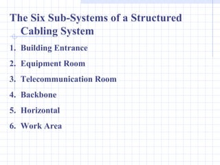
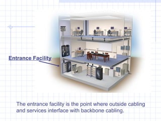
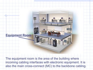
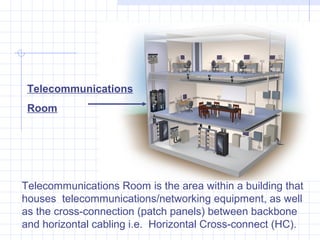
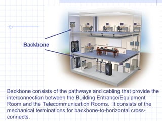
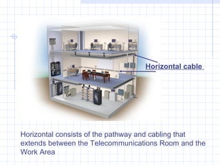
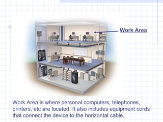
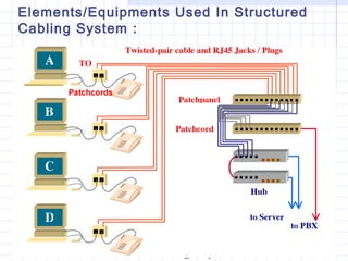
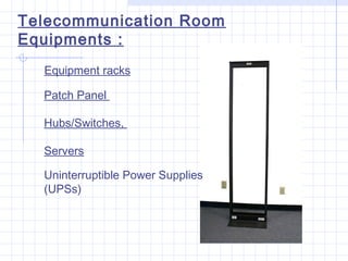
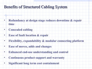
Structured Cabling
A Basic Approach!
Structured Cabling System


 A Structured Cabling System is a cabling and
connectivity products that integrates data, voice, video
and various management system of a building
The Six Sub-Systems of a Structured
  Cabling System
1. Building Entrance
2. Equipment Room
3. Telecommunication Room
4. Backbone
5. Horizontal
6. Work Area
Entrance Facility


   The entrance facility is the point where outside cabling
   and services interface with backbone cabling.
Equipment Room


The equipment room is the area of the building where
incoming cabling interfaces with electronic equipment. It is
also the main cross-connect (MC) to the backbone cabling.
Telecommunications
 Room


Telecommunications Room is the area within a building that
houses telecommunications/networking equipment, as well
as the cross-connection (patch panels) between backbone
and horizontal cabling i.e. Horizontal Cross-connect (HC).
Backbone


Backbone consists of the pathways and cabling that provide the
interconnection between the Building Entrance/Equipment
Room and the Telecommunication Rooms. It consists of the
mechanical terminations for backbone-to-horizontal cross-
connects.
Horizontal cable


Horizontal consists of the pathway and cabling that
extends between the Telecommunications Room and the
Work Area
Work Area


Work Area is where personal computers, telephones,
printers, etc are located. It also includes equipment cords
that connect the device to the horizontal cable.
Elements/Equipments Used In Structured
Cabling System :


            Figure 1

 Figure 1
Telecommunication Room
Equipments :
  Equipment racks

  Patch Panel

  Hubs/Switches,

  Servers

  Uninterruptible Power Supplies
  (UPSs)
Cabling Used in the System
• The most common (and lowest cost) twisted pair
  cabling is unshielded twisted pair (UTP). It is
  produced in 4 pair, 24/25 pair and 96/100 pair sizes.
• A foil shielded version of the twisted pair is FTP. An
  aluminum shield is wrapped around all pairs under a
  PVC sheath. The purpose of FTP is to prevent high
  intensity electromagnetic interference entering the
  cable.
• A version of twisted pair cable in which the
  individual pairs are shielded from each other using
  an aluminum foil around each pair is called shielded
  twisted pair or STP or ScTP. The purposes of
  individually shielding pairs is to reduce cross-talk
  interference between the pairs.
Categories of Transmission and Classes of Operation
•   To distinguish between the various levels of transmission quality
    in both cable and termination components, the term Category
    is used.
•   Ordinary telephone (voice) quality twisted pair is Category 1
    and it only supports low bandwidth classes of operation such as
    the telephone/fax/basic internet connection.
•   Category 5 is commonly used in 4 pair structured cabling of
    office floors to the desk outlets.
•   Category 5 supports 1000Mb/s data rates on a bandwidth of
    100 MHz using all 4 pairs of a 4 pair cable; typical system
    operation is Gigabit Ethernet (1000 Mb/s).
•   Category 6 cable supports a bandwidth of 250 MHz and
    operation of Gigabit Ethernet (1000 Mb/s) on 2 of the 4 pairs of
    a 4 pair cable using them as go/return pairs.
•   Category 5 and Category 6 twisted pair cables are available in
    both UTP and FTP.
•   Category 7 twisted pair is under development expected to be
Cable Characteristic(s) Determining its Category :
The primary determinate of transmission quality is the
frequency and accuracy of the twist rate of each pair as well
as the uniformity and accuracy of its physical construction.


Category 1 twisted pair (ordinary telephone cable) has
a very loose and infrequent pair twist.


Category 5/6 has a very frequent pair twist with unique
twist rates for each pair. A critical aspect of installation is
to maintain these pair twist to within 10-13mm of the
actual wire termination points at sockets and not to
disrupt pair twists and wire geometry through poor
installation practices.
Cabling Management :

Good cable management is important and must adhere
today to local codes, EIA/TIA, and the National Electrical
Code (NEC) rules.

Proper hooks and cable trays should be used.
Benefits of Structured Cabling System


•   Redundancy at design stage reduces downtime & repair
    time
•   Concealed cabling
•   Ease of fault location & repair
•   Flexibility, expandability & modular connecting platform
•   Ease of moves, adds and changes
•   Enhanced end-use understanding and control
•   Continuous product support and warranty
•   Significant long term cost containment

Structure cabling a basic approach

  • 1.
  • 2.
    Structured Cabling System A Structured Cabling System is a cabling and connectivity products that integrates data, voice, video and various management system of a building
  • 3.
    The Six Sub-Systemsof a Structured Cabling System 1. Building Entrance 2. Equipment Room 3. Telecommunication Room 4. Backbone 5. Horizontal 6. Work Area
  • 4.
    Entrance Facility The entrance facility is the point where outside cabling and services interface with backbone cabling.
  • 5.
    Equipment Room The equipmentroom is the area of the building where incoming cabling interfaces with electronic equipment. It is also the main cross-connect (MC) to the backbone cabling.
  • 6.
    Telecommunications Room Telecommunications Roomis the area within a building that houses telecommunications/networking equipment, as well as the cross-connection (patch panels) between backbone and horizontal cabling i.e. Horizontal Cross-connect (HC).
  • 7.
    Backbone Backbone consists ofthe pathways and cabling that provide the interconnection between the Building Entrance/Equipment Room and the Telecommunication Rooms. It consists of the mechanical terminations for backbone-to-horizontal cross- connects.
  • 8.
    Horizontal cable Horizontal consistsof the pathway and cabling that extends between the Telecommunications Room and the Work Area
  • 9.
    Work Area Work Areais where personal computers, telephones, printers, etc are located. It also includes equipment cords that connect the device to the horizontal cable.
  • 10.
    Elements/Equipments Used InStructured Cabling System : Figure 1 Figure 1
  • 11.
    Telecommunication Room Equipments : Equipment racks Patch Panel Hubs/Switches, Servers Uninterruptible Power Supplies (UPSs)
  • 12.
    Cabling Used inthe System • The most common (and lowest cost) twisted pair cabling is unshielded twisted pair (UTP). It is produced in 4 pair, 24/25 pair and 96/100 pair sizes. • A foil shielded version of the twisted pair is FTP. An aluminum shield is wrapped around all pairs under a PVC sheath. The purpose of FTP is to prevent high intensity electromagnetic interference entering the cable. • A version of twisted pair cable in which the individual pairs are shielded from each other using an aluminum foil around each pair is called shielded twisted pair or STP or ScTP. The purposes of individually shielding pairs is to reduce cross-talk interference between the pairs.
  • 16.
    Categories of Transmissionand Classes of Operation • To distinguish between the various levels of transmission quality in both cable and termination components, the term Category is used. • Ordinary telephone (voice) quality twisted pair is Category 1 and it only supports low bandwidth classes of operation such as the telephone/fax/basic internet connection. • Category 5 is commonly used in 4 pair structured cabling of office floors to the desk outlets. • Category 5 supports 1000Mb/s data rates on a bandwidth of 100 MHz using all 4 pairs of a 4 pair cable; typical system operation is Gigabit Ethernet (1000 Mb/s). • Category 6 cable supports a bandwidth of 250 MHz and operation of Gigabit Ethernet (1000 Mb/s) on 2 of the 4 pairs of a 4 pair cable using them as go/return pairs. • Category 5 and Category 6 twisted pair cables are available in both UTP and FTP. • Category 7 twisted pair is under development expected to be
  • 17.
    Cable Characteristic(s) Determiningits Category : The primary determinate of transmission quality is the frequency and accuracy of the twist rate of each pair as well as the uniformity and accuracy of its physical construction. Category 1 twisted pair (ordinary telephone cable) has a very loose and infrequent pair twist. Category 5/6 has a very frequent pair twist with unique twist rates for each pair. A critical aspect of installation is to maintain these pair twist to within 10-13mm of the actual wire termination points at sockets and not to disrupt pair twists and wire geometry through poor installation practices.
  • 19.
    Cabling Management : Goodcable management is important and must adhere today to local codes, EIA/TIA, and the National Electrical Code (NEC) rules. Proper hooks and cable trays should be used.
  • 20.
    Benefits of StructuredCabling System • Redundancy at design stage reduces downtime & repair time • Concealed cabling • Ease of fault location & repair • Flexibility, expandability & modular connecting platform • Ease of moves, adds and changes • Enhanced end-use understanding and control • Continuous product support and warranty • Significant long term cost containment