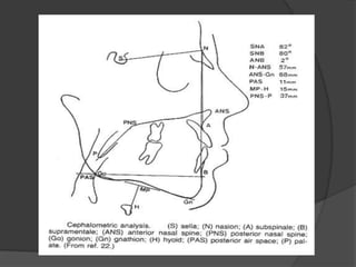
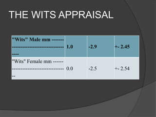
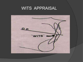
By

Shameel ahmed shariff
Introduction
Assessment of cranio-facial structures
forms a part of orthodontic diagnosis.
 Craniometry can be said to be the
forerunner of cephalometry.
 Craniometry involved measurements of
cranio facial dimensions of skulls of dead
persons.
 This method was not practical in living
individual due to soft tissue envelope that
made direct measurement difficult and far
reliable.

Types


Lateral cephalogram; provides lateral
view of skull.



Frontal cephalogram; provides
anteroposterior view of skull.
Uses
Helps in orthodontic diagnosis.
 Helps in classification of skeletal and
dental abnormalities.
 Helps in planning treatment of an
individual.
 Helps in evaluation of treatment results.
 Helps in predicting growth related
changes.

Technical aspect


Cephalometric radiographs are taken using
an apparatus that consist of an x ray source
and an head holding device called
cephalostat.



Cephalostat consists of two ear rods
preventing movement of head.



Vertical stabilisation of head is by orbital
pointer contacting lower border of orbit.


Upper part of face is supported by forehead
clamp positioned above the region of nasal
bridge.



The distance between the x ray source and
mid saggital plane of the patient is fixed at 5
feet.



Thus the equipment helps in standardising
the radiographs.









S
Sella: the midpoint of Sella Turcica
N
Nasion: the extreme anterior point on the
frontonasal suture
sna
Spina nasalis anterior: the extreme anterior
point on the maxilla
snp
Spina nasalis posterior: the extreme posterior
point on the maxilla
Pt
Pterygoid point: the extreme superior point of
the pterygopalatine fossa








A
Point A: the deepest point in the curvature of
the maxillary alveolar process
B
Point B: the deepest point in the curvature of
the mandibular alveolar process
Pg
Pogonion: the extreme anterior point of the chin
Me
Menton: the extreme inferior point of the chin
Gn
Gnathion: the midpoint between pogonion and
menton









Go
Gonion: the midpoint of the mandibular angle between
ramus and corpus mandibulae
O
Opisthion: the posterior border of foramen magnum
Ba
Basion: the anterior border of foramen magnum
Cd
Condylion: the extreme superior point of the condyle
Fc
Fossa cranialis: the intersection between the sphenoidal
plane and the larger wing of the sphenoid
L
Lambda: the midpoint of the lambdoid suture on the
external cranial contour
Downs analysis;


It is one of the most frequently used
cephalometric analysis.



Downs analysis consists of ten
parameters of which five are skeletal
and five are dental.
Skeletal parameters;


Facial angle;
it is the inside inferior angle formed by
intersection of nasion-pogonion plane and
F.H. plane.
average value; 87.8’ ( 82 – 95’)
significance; indication of antero- posterior
positioning of mandible in relation to upper
face. Angle is increased in skeletal class III
with prominent chin while decreased in
skeletal class II.


Angle of convexity;
Nasion-point A to point A – pogonion.
Average value; 0’ ( -8.5 to 10’).
Significance; A positive angle suggest a
prominent maxillary denture bace in relation
to mandible.
Negative angle is indicative of prognathic
profile.


A-B plane angle;
point A – point B to nasion – pogonion.
Average value; -4.6’ ( -9 to 0’)
Significance; indicative of maxillo mandibular
relationship in relation to facial plane.
Negative since point B is positioned behind
point A.
Positive in class III malocclusion.


Mandibular plane angle;
Intersection of mandibular plane with F.H.
Plane.
Average value; 21.9’ ( 17 to 28’)



Y-Axis;
Sella gnathion to F.H. plane.
Average value; 59’ ( 53’ to 66’)
Angle is larger in class II facial patterns.
Indicates growth pattern of a individual.
DENTAL PARAMETERS


Cant of occlusal plane;
OCCLUSAL PLANE TO F.H. Plane
Average value; 9.3 ( 1.5 to 14’)
Gives a measure of slope of occlusal plane
relative to F.H. Plane.



Inter incisal angle;
Angle between long axes of upper and lower
incisors.
Average value: 135.4’ ( 130 to 150.5’)
increased in class I bimaxillary protrusion.


Incisor occlusal plane angle;
This is the inside inferior angle formed by the
intersection between the long axis of lover central
incisor and the occlusal plane and is read as a plus
or minus deviation from a right angle
Average value: 14.5” ( 3.5 to 20’)
An increase in this angle is suggestive of increased
lover incisor proclination.

•

Incisor mandibular plane angle:
This angel is formed by intersection of the long axis
of the lower incisor and the mandibular plane.
Average value: 1.4’(-8.2 to 7’)
An increase in this angle is suggestive of increased
lower incisor proclination.


Upper incisor to A-pog line:
This is a linear measurement between the
incisal edge of the maxillary central incisor and
the line joining point A to pogonion. This
distance is on an average 2.7 mm(rang-1 to 5
mm)
The measurement is more in patients
presenting with upper incisor proclination.
Steiners analysis
SNA (Maxillary position)

82.0

SNB (Mandibular position)

80

ANB (Maxillary/Mandibular relation)

2

l to NA (Upper incisors to NA mm)

4mm

l to NA (Upper incisors to NA degree)

22

l to NB (Lower incisors to NB mm)

4mm

l to NB (Lower incisors to NB degree)

25

l to l (lnter-incisal angle)

131

SN to GoGn (Mandibular plane angle

32

SN to occlusal plane

14
TWEED ANALYSIS
FMA (Frankfurt plane to
mandibular plane)

25.0

25.8

+- 5.19

FMIA (Frankfurt plane to lower
65.0
incisor angulation)

62.7

+- 6,97

IMPA (Lower incisor to
mandibular plane)

91.5

+- 5.97

90.0
TWEEDS TRIANGLE
THE WITS APPRAISAL
"Wits" Male mm ------------------------------------ 1.0
---"Wits" Female mm ----------------------------------- 0.0
--

-2.9

+- 2.45

-2.5

+- 2.54
WITS APPRAISAL
0dec cephalometrics final (1)

0dec cephalometrics final (1)

  • 1.
  • 2.
    Introduction Assessment of cranio-facialstructures forms a part of orthodontic diagnosis.  Craniometry can be said to be the forerunner of cephalometry.  Craniometry involved measurements of cranio facial dimensions of skulls of dead persons.  This method was not practical in living individual due to soft tissue envelope that made direct measurement difficult and far reliable. 
  • 3.
    Types  Lateral cephalogram; provideslateral view of skull.  Frontal cephalogram; provides anteroposterior view of skull.
  • 4.
    Uses Helps in orthodonticdiagnosis.  Helps in classification of skeletal and dental abnormalities.  Helps in planning treatment of an individual.  Helps in evaluation of treatment results.  Helps in predicting growth related changes. 
  • 5.
    Technical aspect  Cephalometric radiographsare taken using an apparatus that consist of an x ray source and an head holding device called cephalostat.  Cephalostat consists of two ear rods preventing movement of head.  Vertical stabilisation of head is by orbital pointer contacting lower border of orbit.
  • 6.
     Upper part offace is supported by forehead clamp positioned above the region of nasal bridge.  The distance between the x ray source and mid saggital plane of the patient is fixed at 5 feet.  Thus the equipment helps in standardising the radiographs.
  • 8.
         S Sella: the midpointof Sella Turcica N Nasion: the extreme anterior point on the frontonasal suture sna Spina nasalis anterior: the extreme anterior point on the maxilla snp Spina nasalis posterior: the extreme posterior point on the maxilla Pt Pterygoid point: the extreme superior point of the pterygopalatine fossa
  • 9.
         A Point A: thedeepest point in the curvature of the maxillary alveolar process B Point B: the deepest point in the curvature of the mandibular alveolar process Pg Pogonion: the extreme anterior point of the chin Me Menton: the extreme inferior point of the chin Gn Gnathion: the midpoint between pogonion and menton
  • 10.
          Go Gonion: the midpointof the mandibular angle between ramus and corpus mandibulae O Opisthion: the posterior border of foramen magnum Ba Basion: the anterior border of foramen magnum Cd Condylion: the extreme superior point of the condyle Fc Fossa cranialis: the intersection between the sphenoidal plane and the larger wing of the sphenoid L Lambda: the midpoint of the lambdoid suture on the external cranial contour
  • 11.
    Downs analysis;  It isone of the most frequently used cephalometric analysis.  Downs analysis consists of ten parameters of which five are skeletal and five are dental.
  • 12.
    Skeletal parameters;  Facial angle; itis the inside inferior angle formed by intersection of nasion-pogonion plane and F.H. plane. average value; 87.8’ ( 82 – 95’) significance; indication of antero- posterior positioning of mandible in relation to upper face. Angle is increased in skeletal class III with prominent chin while decreased in skeletal class II.
  • 13.
     Angle of convexity; Nasion-pointA to point A – pogonion. Average value; 0’ ( -8.5 to 10’). Significance; A positive angle suggest a prominent maxillary denture bace in relation to mandible. Negative angle is indicative of prognathic profile.
  • 14.
     A-B plane angle; pointA – point B to nasion – pogonion. Average value; -4.6’ ( -9 to 0’) Significance; indicative of maxillo mandibular relationship in relation to facial plane. Negative since point B is positioned behind point A. Positive in class III malocclusion.
  • 15.
     Mandibular plane angle; Intersectionof mandibular plane with F.H. Plane. Average value; 21.9’ ( 17 to 28’)  Y-Axis; Sella gnathion to F.H. plane. Average value; 59’ ( 53’ to 66’) Angle is larger in class II facial patterns. Indicates growth pattern of a individual.
  • 16.
    DENTAL PARAMETERS  Cant ofocclusal plane; OCCLUSAL PLANE TO F.H. Plane Average value; 9.3 ( 1.5 to 14’) Gives a measure of slope of occlusal plane relative to F.H. Plane.  Inter incisal angle; Angle between long axes of upper and lower incisors. Average value: 135.4’ ( 130 to 150.5’) increased in class I bimaxillary protrusion.
  • 17.
     Incisor occlusal planeangle; This is the inside inferior angle formed by the intersection between the long axis of lover central incisor and the occlusal plane and is read as a plus or minus deviation from a right angle Average value: 14.5” ( 3.5 to 20’) An increase in this angle is suggestive of increased lover incisor proclination. • Incisor mandibular plane angle: This angel is formed by intersection of the long axis of the lower incisor and the mandibular plane. Average value: 1.4’(-8.2 to 7’) An increase in this angle is suggestive of increased lower incisor proclination.
  • 18.
     Upper incisor toA-pog line: This is a linear measurement between the incisal edge of the maxillary central incisor and the line joining point A to pogonion. This distance is on an average 2.7 mm(rang-1 to 5 mm) The measurement is more in patients presenting with upper incisor proclination.
  • 19.
    Steiners analysis SNA (Maxillaryposition) 82.0 SNB (Mandibular position) 80 ANB (Maxillary/Mandibular relation) 2 l to NA (Upper incisors to NA mm) 4mm l to NA (Upper incisors to NA degree) 22 l to NB (Lower incisors to NB mm) 4mm l to NB (Lower incisors to NB degree) 25 l to l (lnter-incisal angle) 131 SN to GoGn (Mandibular plane angle 32 SN to occlusal plane 14
  • 21.
    TWEED ANALYSIS FMA (Frankfurtplane to mandibular plane) 25.0 25.8 +- 5.19 FMIA (Frankfurt plane to lower 65.0 incisor angulation) 62.7 +- 6,97 IMPA (Lower incisor to mandibular plane) 91.5 +- 5.97 90.0
  • 22.
  • 23.
    THE WITS APPRAISAL "Wits"Male mm ------------------------------------ 1.0 ---"Wits" Female mm ----------------------------------- 0.0 -- -2.9 +- 2.45 -2.5 +- 2.54
  • 24.