This document provides an overview of cephalometrics including:
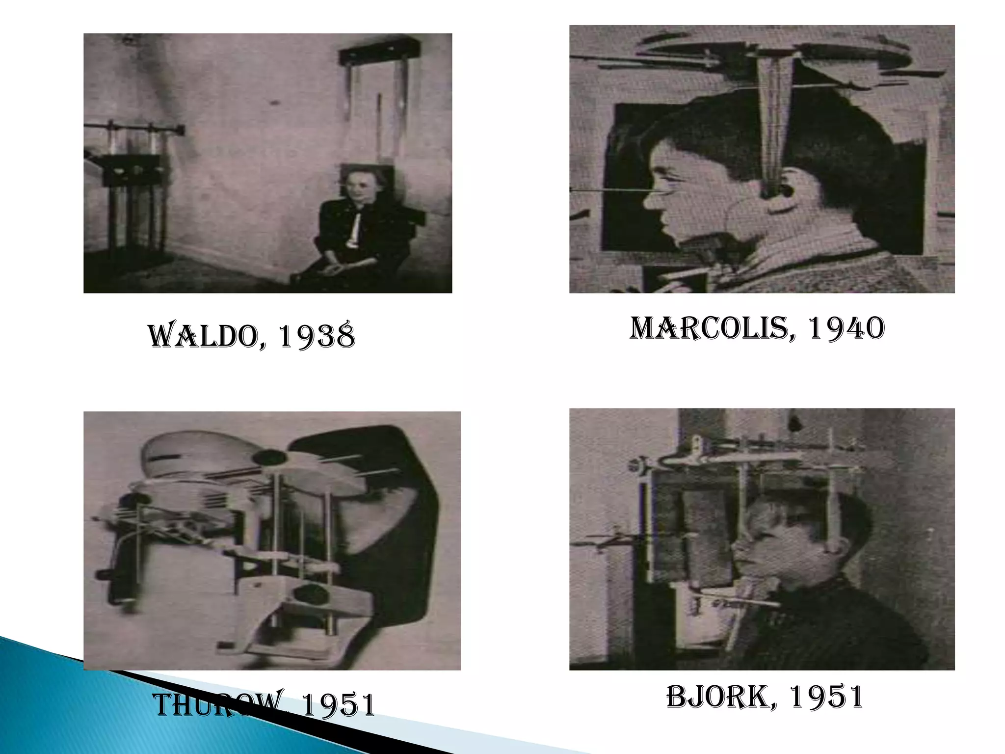
1. A brief history noting its development from craniometry and introduction in the early 20th century.
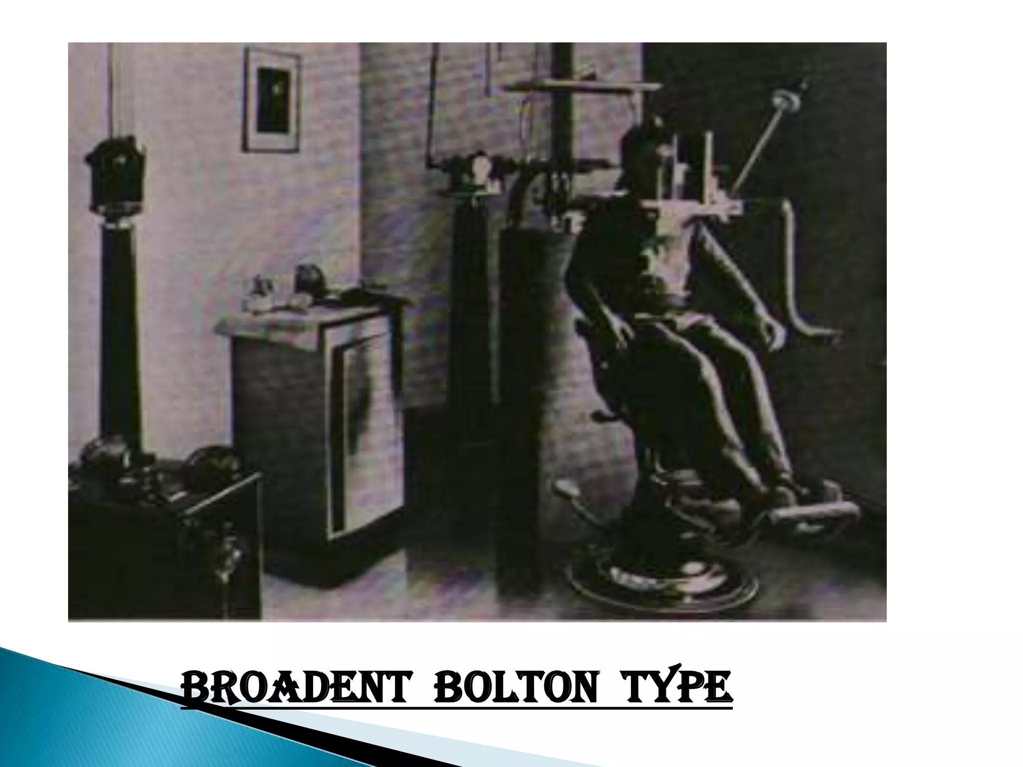
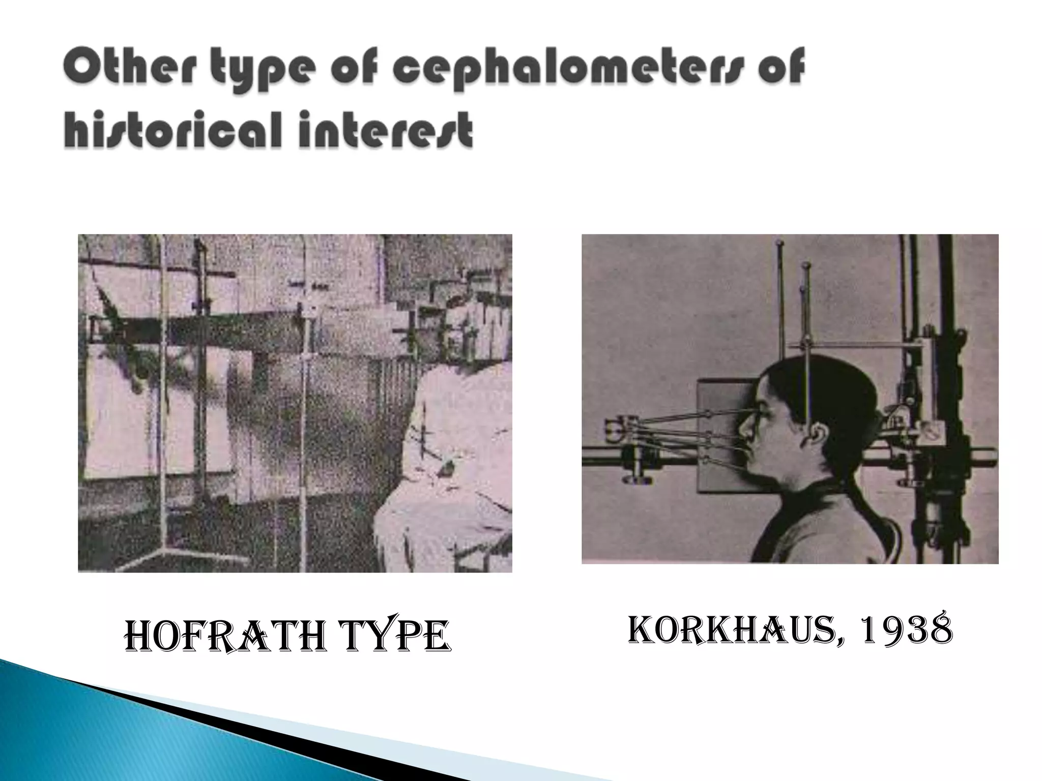
2. A description of common cephalometric equipment including the Broadbent bolton type and highleys type.
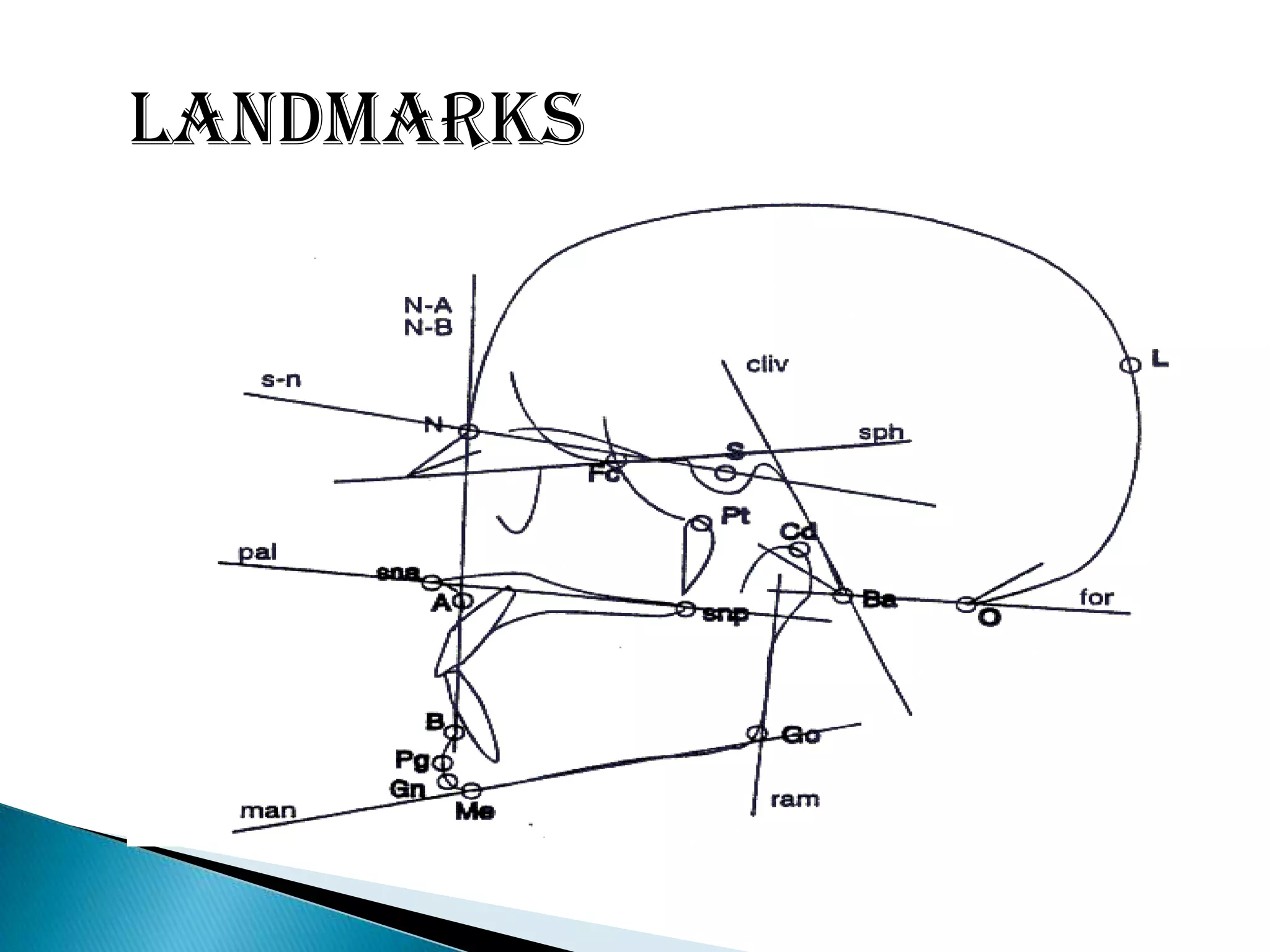
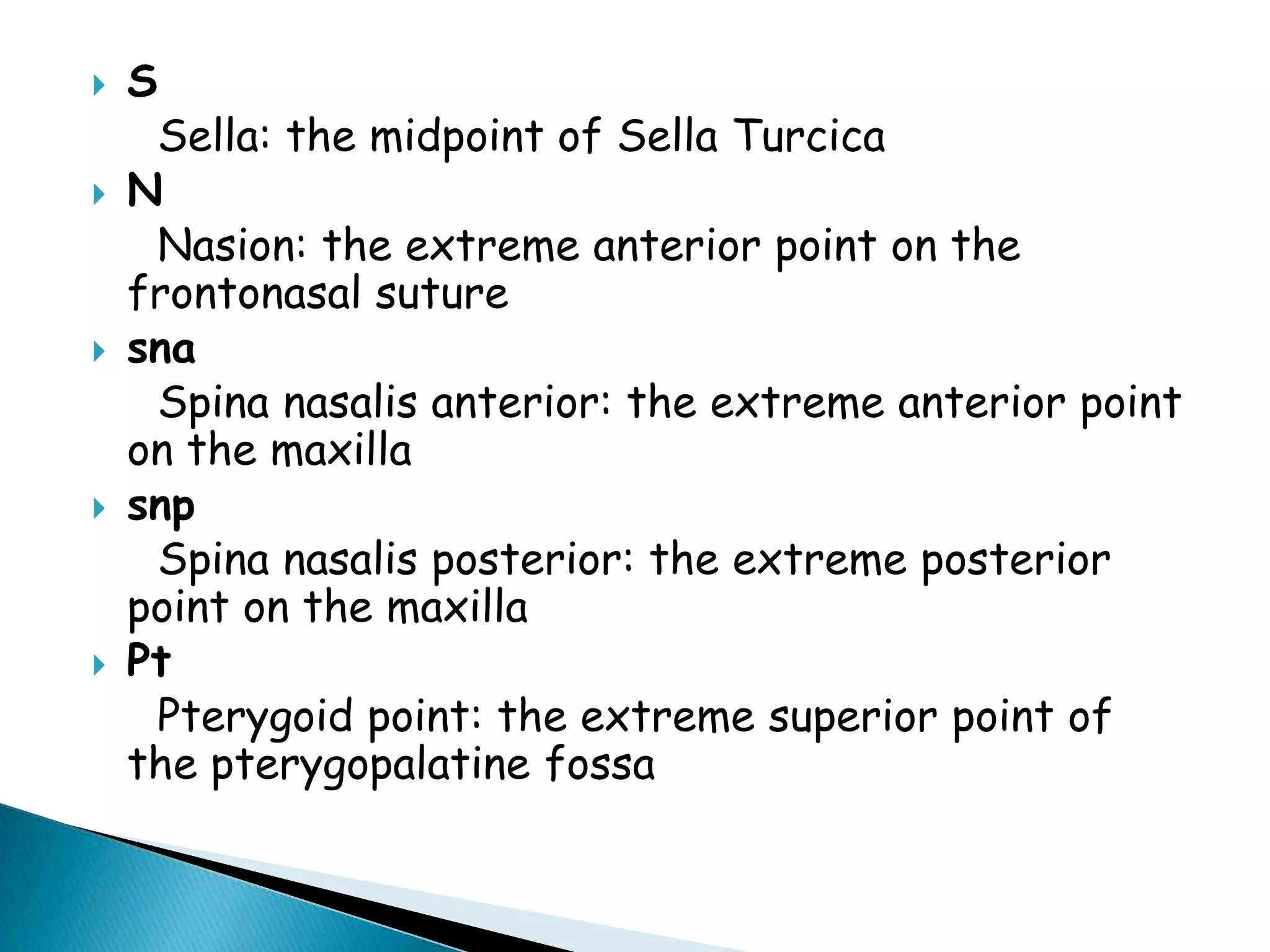
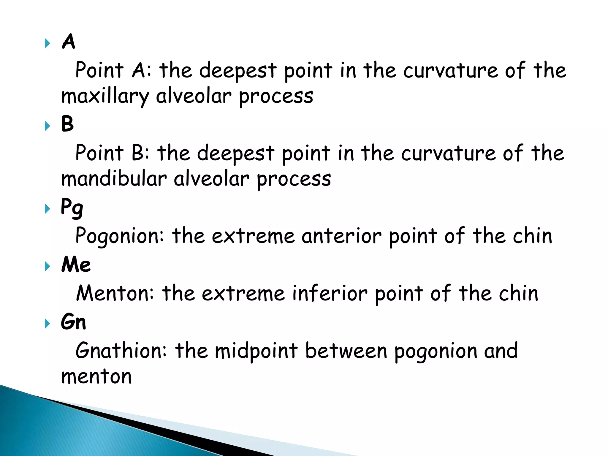
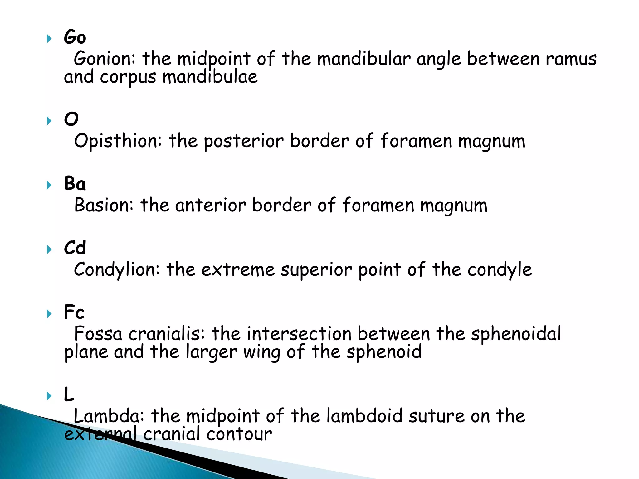
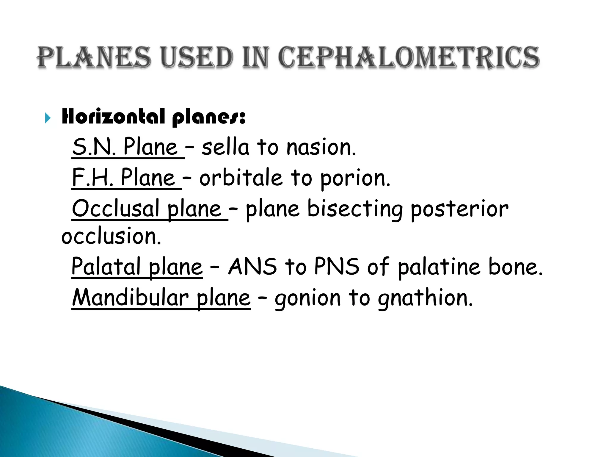
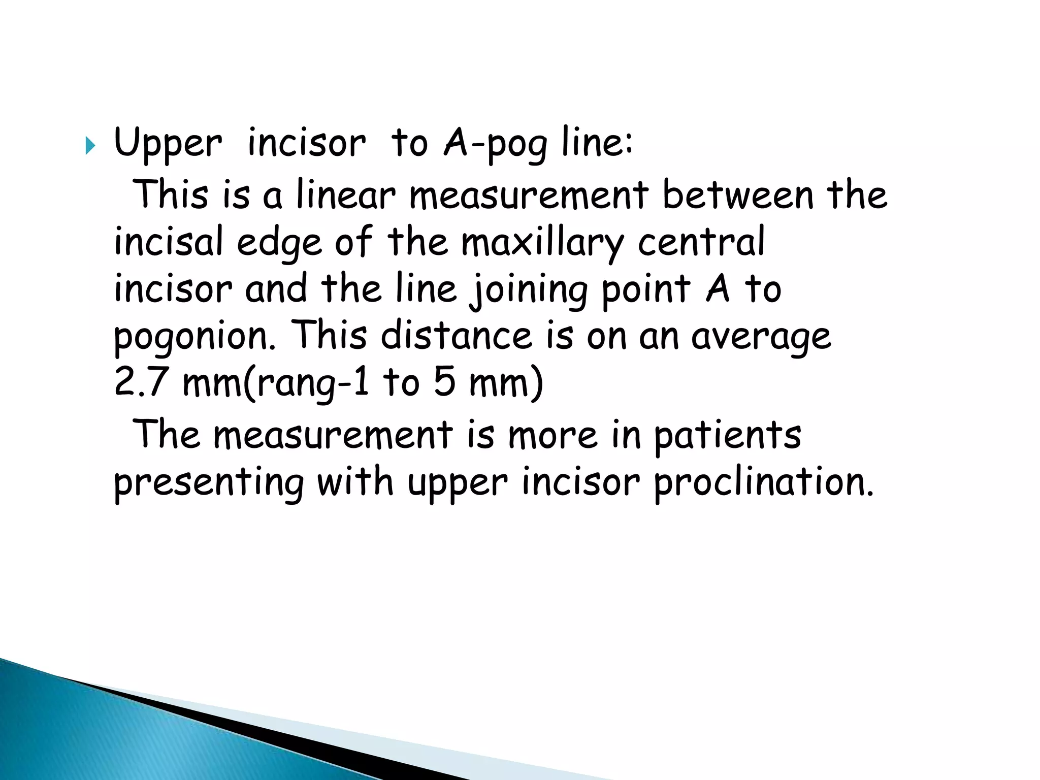
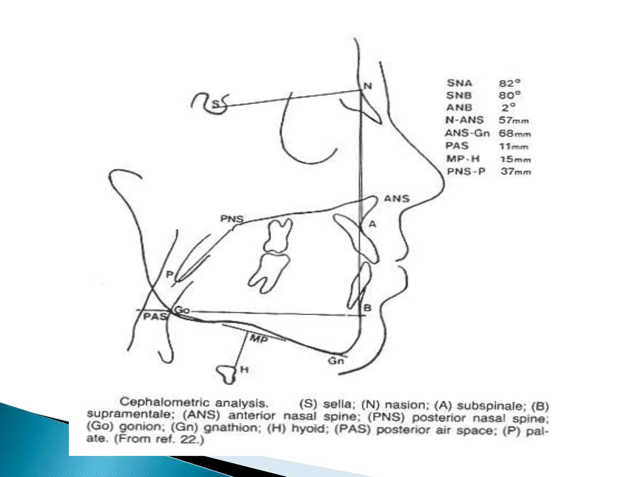
3. An explanation of landmarks and planes used in cephalometric analysis including horizontal planes like SN plane and vertical planes like A-Pog line.
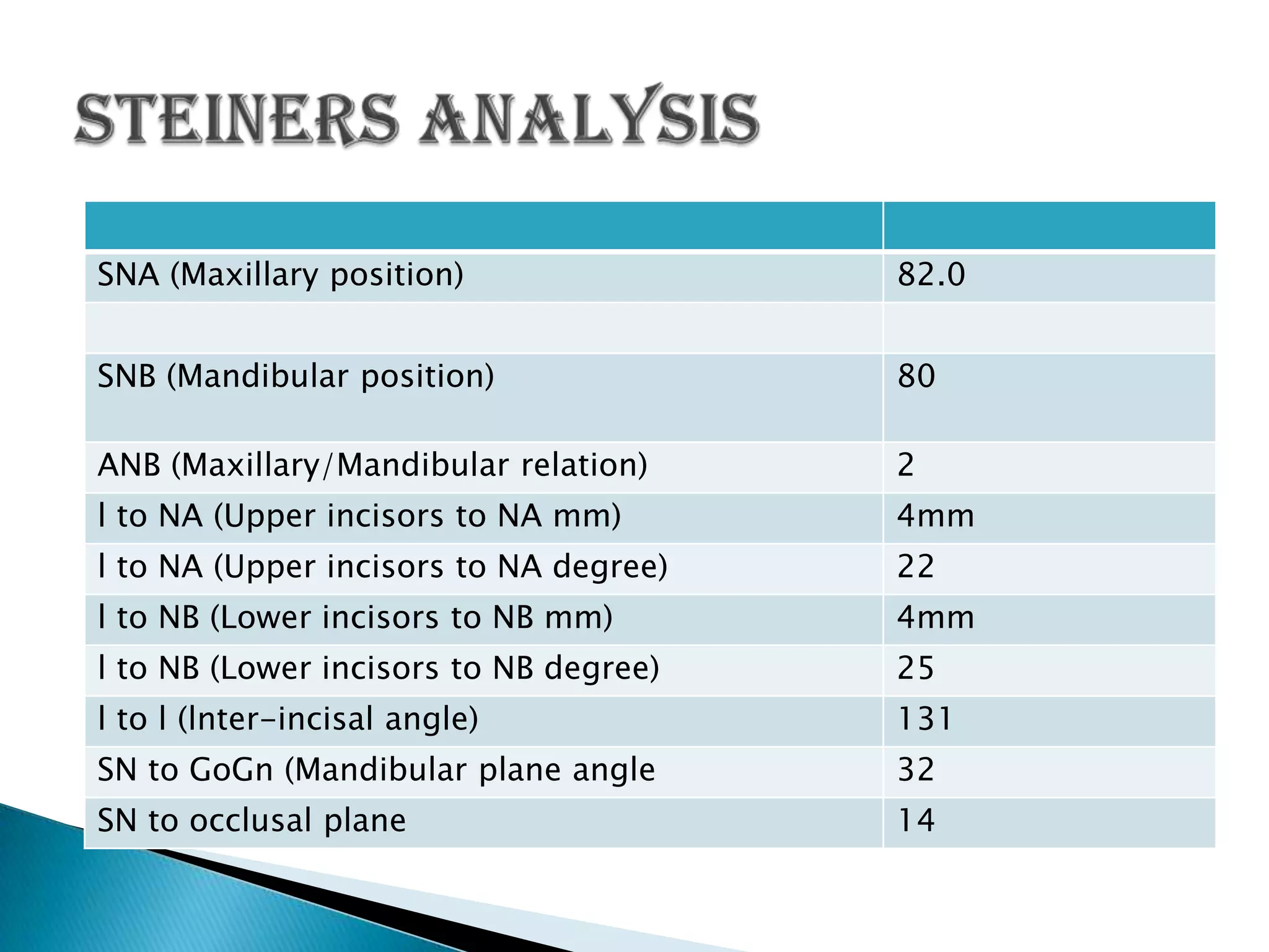
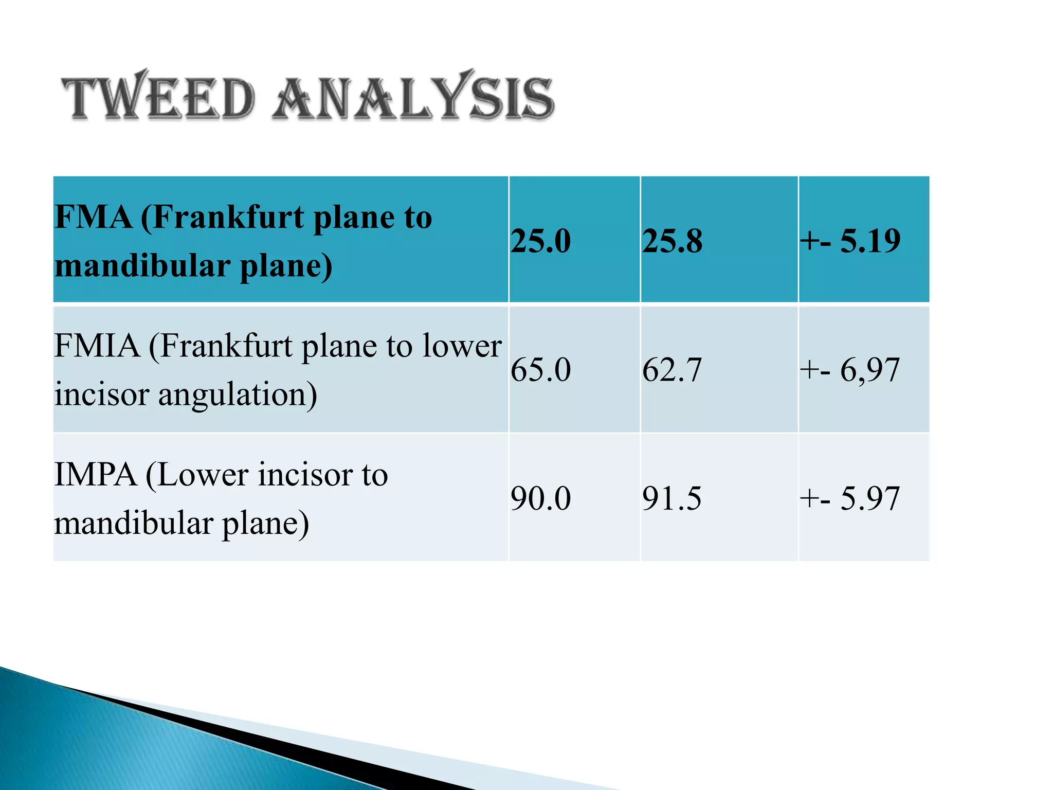
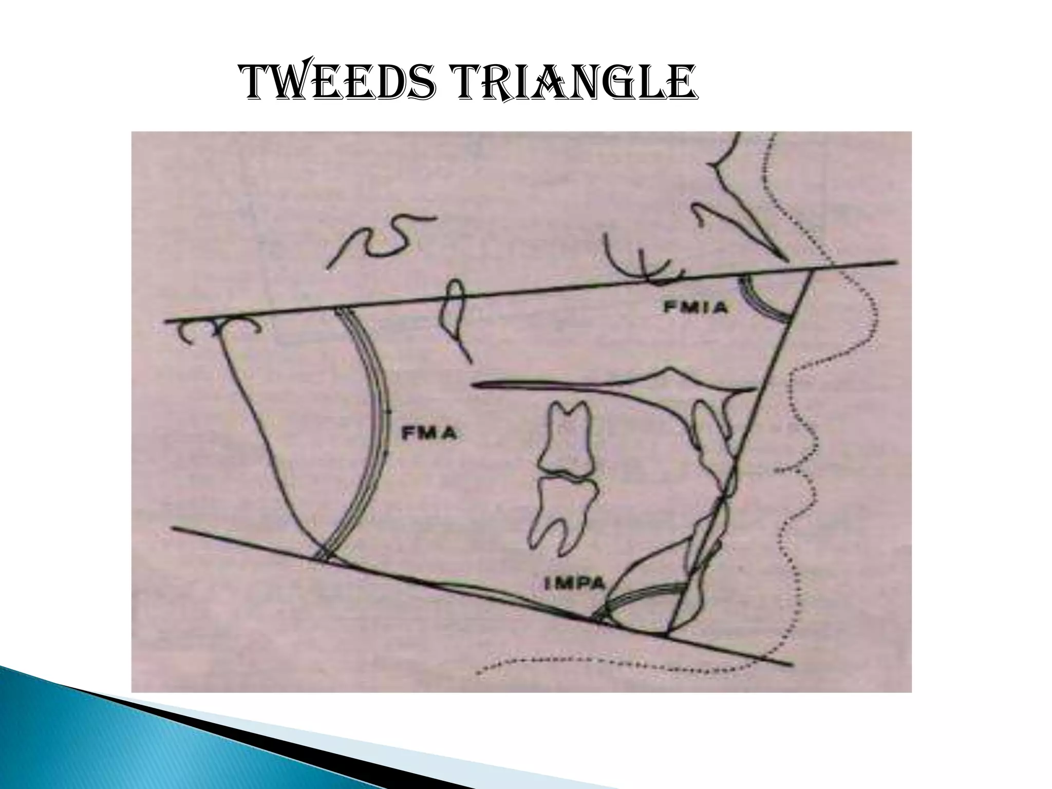
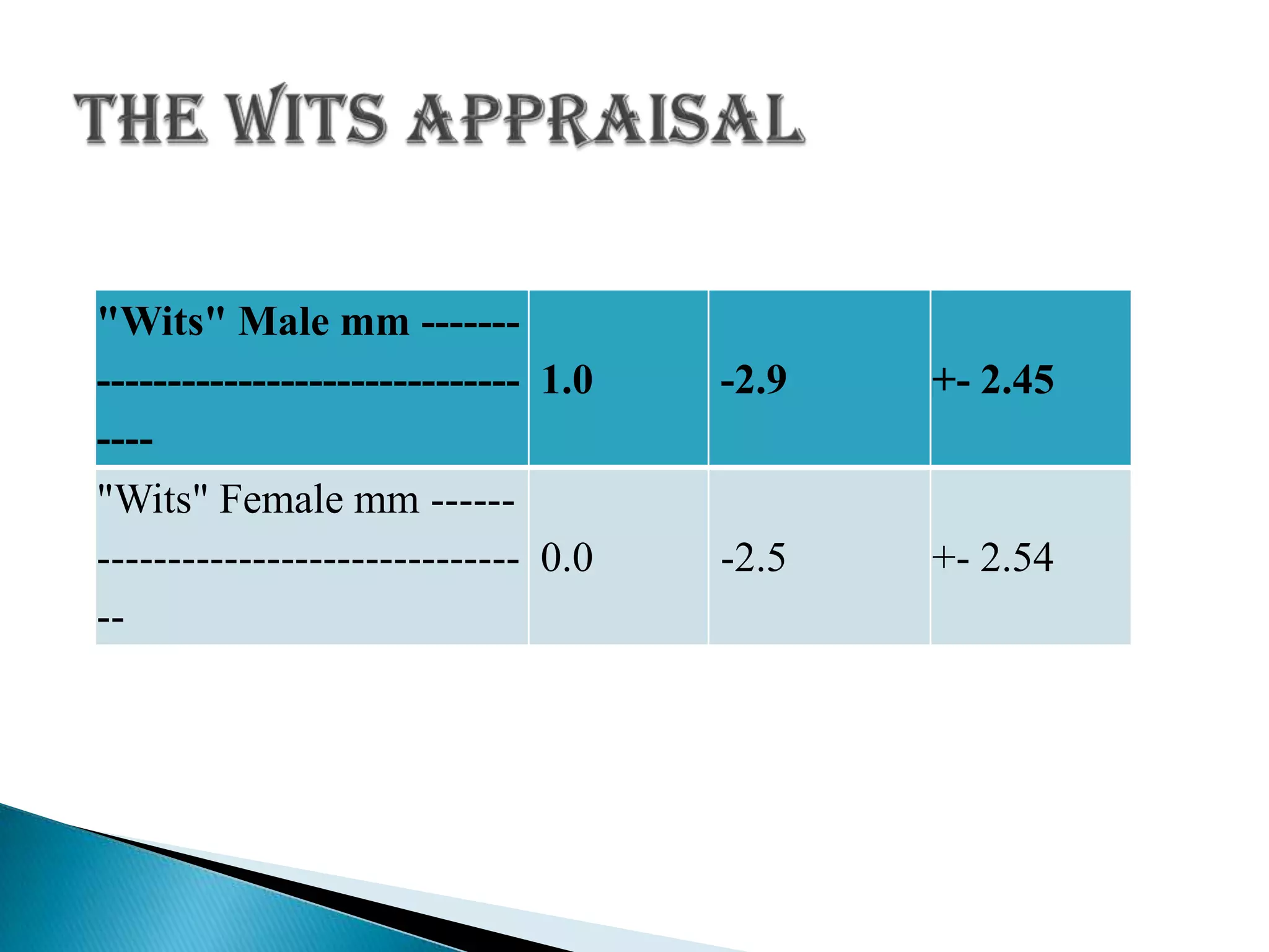
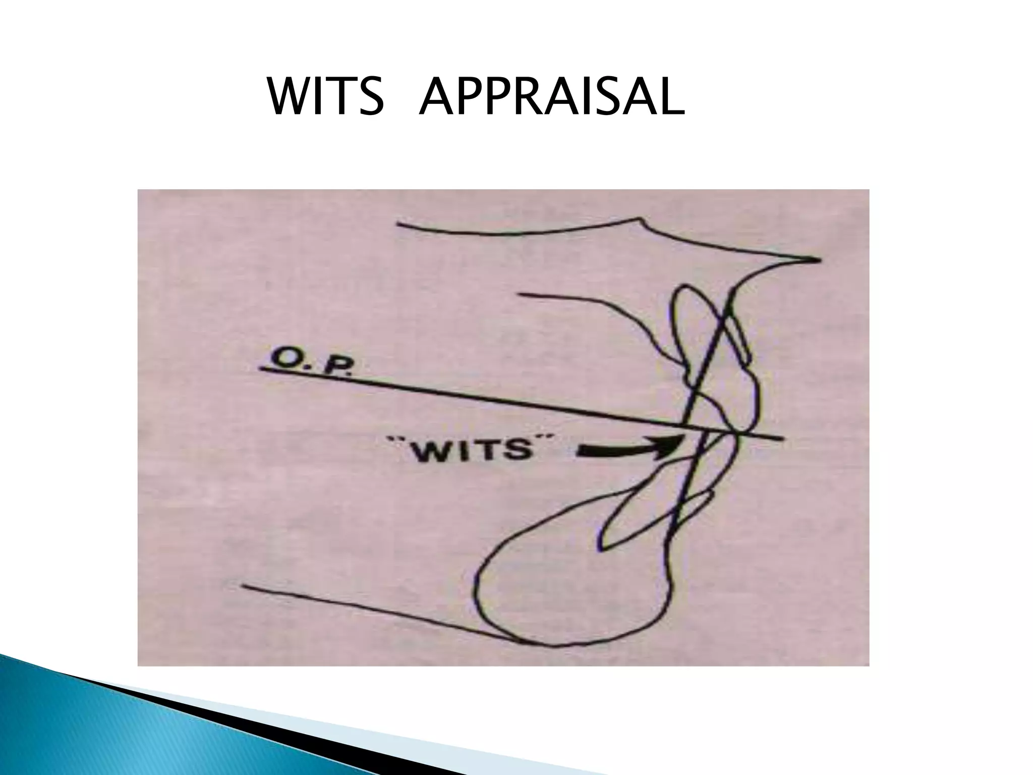
4. A summary of common cephalometric analyses like Downs analysis, Steiner's analysis, and Wits appraisal which are used to evaluate skeletal and dental relationships.