This document discusses methods for stator earth fault protection in generators. It presents:
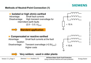
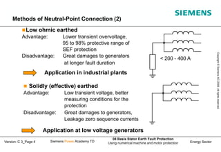
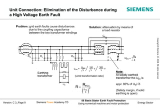
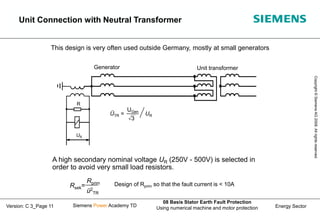
1) Different methods of neutral point grounding and their advantages/disadvantages.
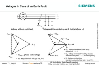
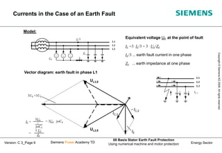
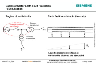
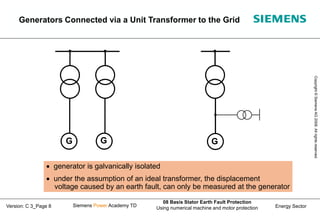
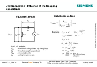
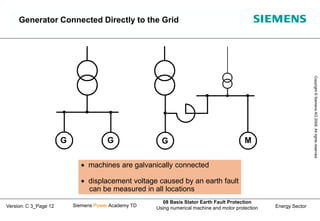
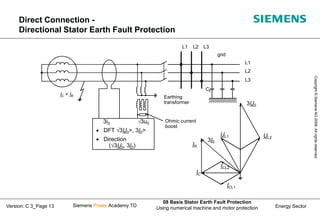
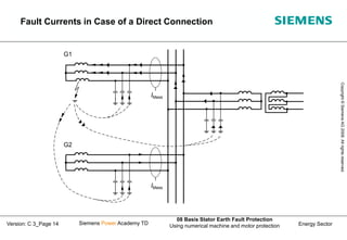
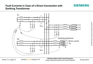
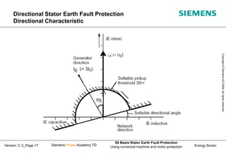
2) How earth fault voltages and currents behave depending on the fault location for different generator connections.
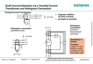
3) Techniques for measuring earth fault currents including use of a toroidal current transformer and Holmgreen connection.