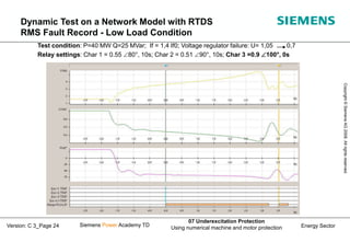
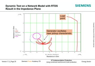
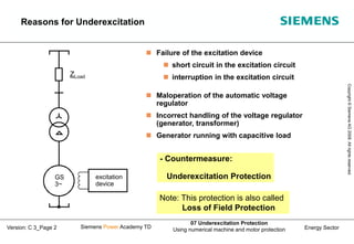
This document discusses underexcitation protection, also called loss of field protection, for synchronous generators. It provides reasons for underexcitation including failures of the excitation device. Consequences of excitation failures can include rotor acceleration, overheating, and grid oscillations. The admittance protection criterion is proposed, which considers how the generator stability limit moves when voltage decreases. It involves transforming the generator capability diagram into an admittance diagram to set straight-line characteristics based on the stability limits.

![Energy Sector
Copyright
©
Siemens
AG
2008.
All
rights
reserved.
Siemens Power Academy TD
07 Underexcitation Protection
Using numerical machine and motor protection
Version: C 3_Page 8
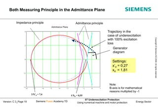
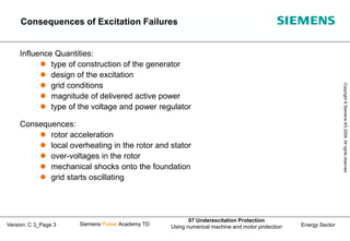
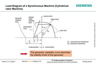
In the case of an under-voltage the generator capability curve
moves to right and reduces the stability limits of the generator
1/xd
0.81/xd
0.85
1 U=1; I=1;
U=0.9; I= 1.11
Stability
limit
Q [p.u]
P [p.u]
Over-excited
Under-excited
Per Unit Capability Diagram of a Synchronous
Generator in the Case of Under-voltage (U = 0.9 UN)](https://image.slidesharecdn.com/07c3underexcitationprotection-230728194941-f7a2c3d8/85/07_C_3_Underexcitation-Protection-ppt-8-320.jpg)
![Energy Sector
Copyright
©
Siemens
AG
2008.
All
rights
reserved.
Siemens Power Academy TD
07 Underexcitation Protection
Using numerical machine and motor protection
Version: C 3_Page 12
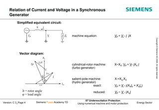
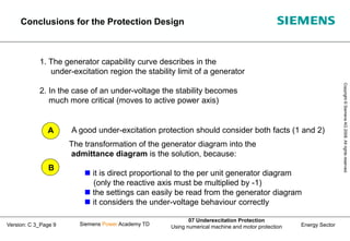
Underexcitation Protection with the Criterion
Admittance Y>
Admittance calculation guarantees a right
behaviour, if the voltages decreases
3 independent characteristics
and 3 timers
characteristic 1,2 is adapted to the
steady-state limit curve;
additional measurement of the field voltage
(release a short trip time)
characteristic 3 is adapted to the
dynamic stability limit curve
blocking of the protection at U<25% UN
a2
a3
a1
char.3 char.2 char.1
G[p.u.]
B[p.u.]
d1
x
1
d2
x
1
d3
x
1
Settings: Can directly be read out from the generator diagram
d
x
1
d1
x
1 a1 = 80°
d1
x
1
0.9
d2
x
1
= 90°
a2
d
x
2
or
1
d3
x
1
= 100° or 110°
a3](https://image.slidesharecdn.com/07c3underexcitationprotection-230728194941-f7a2c3d8/85/07_C_3_Underexcitation-Protection-ppt-12-320.jpg)


![Energy Sector
Copyright
©
Siemens
AG
2008.
All
rights
reserved.
Siemens Power Academy TD
07 Underexcitation Protection
Using numerical machine and motor protection
Version: C 3_Page 16
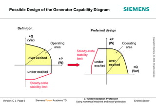
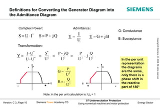
Generator diagram is transferred to the impedance plane (e.g. X=U2/Q).
(Stability limit is represented as a circular characteristic)
characteristic: Offset-MHO
tripping zone inside the circle
characteristic 1, tdelay 0...0,3 s (for high load
generator and field failure)
characteristic 2, tdelay 0,5 - 3 s (for low load
generator, section field voltage failure)
R[p.u.]
X[p.u.]
xd
1
0.5 xd’
Char.2
Char.1
approximation
of stability
limit
Relay settings according
IEEE C37.102-1995
Summary:
• Measuring principle from electromechanical relays,
because impedance measuring elements were only
available
• circle characteristic is a compromise for adaptation
to the generator stability curve
Underexcitation Protection with Criterion Impedance I-ZI<](https://image.slidesharecdn.com/07c3underexcitationprotection-230728194941-f7a2c3d8/85/07_C_3_Underexcitation-Protection-ppt-16-320.jpg)
![Energy Sector
Copyright
©
Siemens
AG
2008.
All
rights
reserved.
Siemens Power Academy TD
07 Underexcitation Protection
Using numerical machine and motor protection
Version: C 3_Page 17
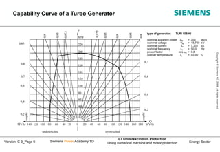
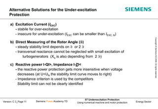
Transformation rule: A circle without zero crossing inverted becomes again a circle
R[p.u.]
X[p.u.]
xd
1
0.5 xd’
Char. 2
Char.1
G[p.u.]
B[p.u.]
d
,
d
d x
1
x
x
2
2
1
x
2
2
,
d
x
2
,
d
Z
1
Y
Impedance plane Admittance plane
Transformation of Criterion Impedance I-ZI<
into the Admittance plane](https://image.slidesharecdn.com/07c3underexcitationprotection-230728194941-f7a2c3d8/85/07_C_3_Underexcitation-Protection-ppt-17-320.jpg)