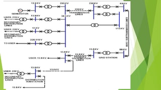
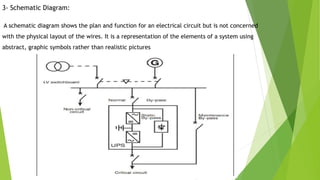
Drawing and Diagram Types
1- Single-Line Diagram:
Single line diagram is also called one line diagram, the single-line diagram may represent
two, three or more actual conductors. These lines are simply intended to show
interconnections between system components rather than the actual wiring and
hookups.
The purpose of single line diagrams is to give a pictorial overview of an electrical system.
The single line does not represent actual wiring; it only indicates that some kind of
connection exists between components.
Overall System Single Line Diagram:
Procedure for preparing a pictorial form of a single line diagram of a transmission and
distribution electric power system like the system shown in Figure (1-21) is by obtaining
single-line diagram for each part of the system and assembling them into one diagram.
2- Circuit Diagram
A circuit diagram is a visual display of an electrical circuit
using either basic images of parts or industry standard symbols.
3- Schematic Diagram:
A schematic diagram shows the plan and function for an electrical circuit but is not concerned
with the physical layout of the wires. It is a representation of the elements of a system using
abstract, graphic symbols rather than realistic pictures
5- Wiring Diagram :
A wiring diagram is a simple visual representation of the physical connections and
physical layout of an electrical system or circuit. It shows how the electrical wires are
interconnected and can also show where fixtures and components may be connected to
the system.

Single Line Diagram.pptx

  • 1.
    Drawing and DiagramTypes 1- Single-Line Diagram: Single line diagram is also called one line diagram, the single-line diagram may represent two, three or more actual conductors. These lines are simply intended to show interconnections between system components rather than the actual wiring and hookups. The purpose of single line diagrams is to give a pictorial overview of an electrical system. The single line does not represent actual wiring; it only indicates that some kind of connection exists between components.
  • 3.
    Overall System SingleLine Diagram: Procedure for preparing a pictorial form of a single line diagram of a transmission and distribution electric power system like the system shown in Figure (1-21) is by obtaining single-line diagram for each part of the system and assembling them into one diagram.
  • 5.
    2- Circuit Diagram Acircuit diagram is a visual display of an electrical circuit using either basic images of parts or industry standard symbols.
  • 6.
    3- Schematic Diagram: Aschematic diagram shows the plan and function for an electrical circuit but is not concerned with the physical layout of the wires. It is a representation of the elements of a system using abstract, graphic symbols rather than realistic pictures
  • 7.
    5- Wiring Diagram: A wiring diagram is a simple visual representation of the physical connections and physical layout of an electrical system or circuit. It shows how the electrical wires are interconnected and can also show where fixtures and components may be connected to the system.