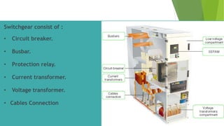
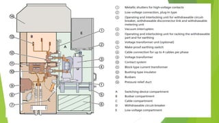
The document summarizes key components and operating principles of switchgear, including circuit breakers, current transformers, and voltage transformers. It describes:
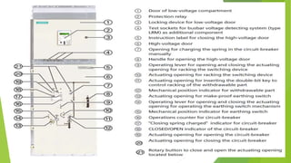
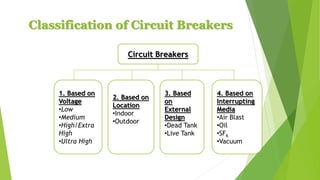
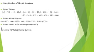
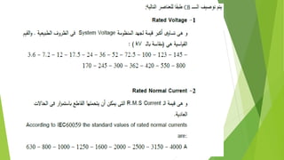
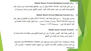
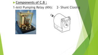
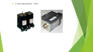
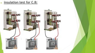
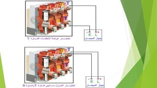
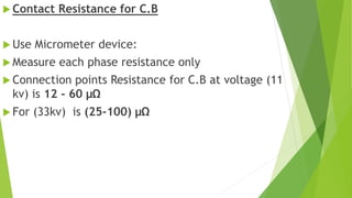
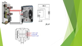
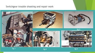
- Circuit breakers consist of contacts, operating mechanisms, trip and close coils, and auxiliary switches. They are rated by voltage and breaking capacity.
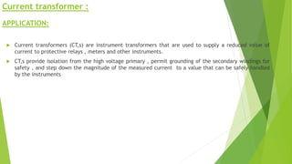
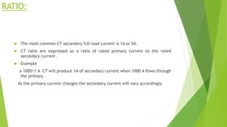
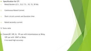
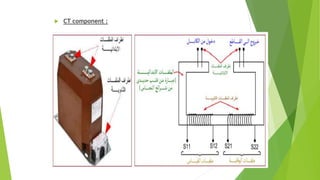
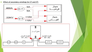
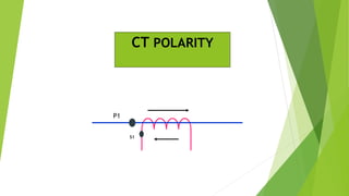
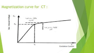
- Current transformers reduce high currents to safely measurable levels for meters and relays. They are rated by voltage, current ratios, and accuracy class.
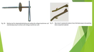
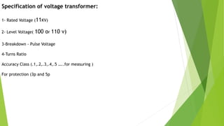
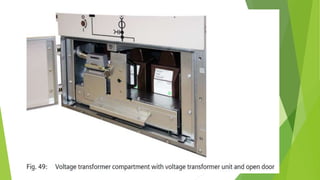
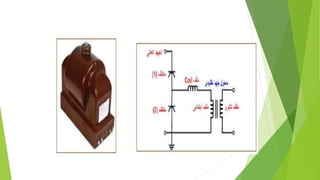
- Voltage transformers reduce high voltages to safely measurable levels. They are rated by voltage, turns ratio, and accuracy class.