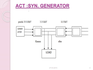
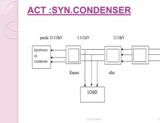
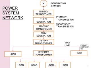
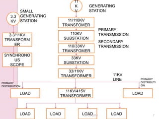
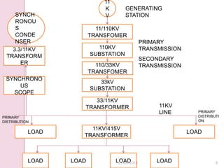
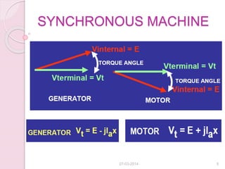
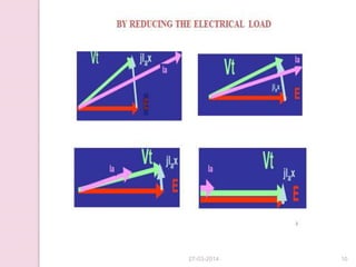
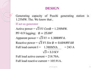
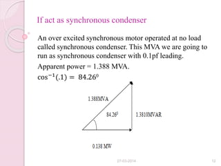
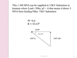
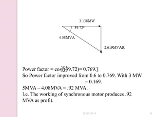
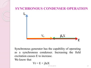
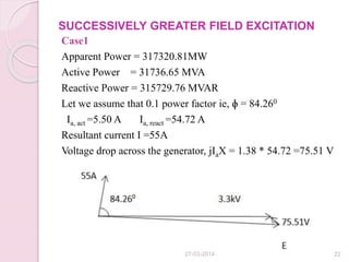
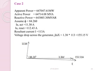
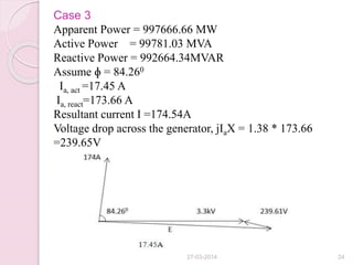
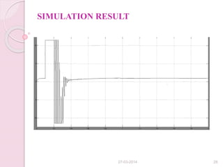
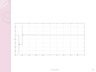
Linux Systems Programming: Inter Process Communication (IPC) using Pipes
Power factor improvement method using synchronous condenser
1. POWER FACTOR
IMPROVEMENT
IN GRID USING SMALL HYDRO
GENERATING STATION
PRESENTED BY,
AKHIL.A.G TJAKEEE003
ANUSHA.K.BINO TJAKEEE010
VIJISHA.E.V
TJAKEEE051
VISHAG RAVEENDAN TJAKEEE052
Guide: Anil sir
27-03-2014 1
2. INTRODUCTION
Power
Power factor
Synchronization
Synchronous machine
Synchronous condenser
Current situation
27-03-2014 2
11. DESIGN
Generating capacity of Peechi generating station is
1.25MW. The. We know that ,
If act as generator
Active power = 3 𝑉𝐼 𝐶𝑜𝑠∅ = 1.250MW.
PF=0.9 lagging; ∅ = 25.840
Apparent power = 3 𝑉𝐼 = 1.388𝑀𝑉𝐴.
Reactive power = 3 𝑉𝐼 𝑆𝑖𝑛 ∅ = 0.604𝑀𝑉𝐴𝑅
Full load current I = 1.388MVA = 243 A
3 ∗ 3.3 KV
Full load active current = 218.70A.
Full load reactive current = 105.91A.
27-03-2014 11
12. If act as synchronous condenser
An over excited synchronous motor operated at no load
called synchronous condenser. This MVA we are going to
run as synchronous condenser with 0.1pf leading.
Apparent power = 1.388 MVA.
cos−1
(.1) = 84.260
27-03-2014 12
13. This 1.388 MVA can be supplied to 33KV Substation in
kannara where Load =3Mw, pf = .6 that means it draws 5
MVA from feeding Ollur 33kV Substation
Pf =0.6
∅ = 53.130
27-03-2014 13
14. Power factor = cos
〖(39.72)= 0.769.〗
So Power factor improved from 0.6 to 0.769. With 3 MW
= 0.169.
5MVA – 4.08MVA = .92 MVA.
I.e. The working of synchronous motor produces .92
MVA as profit.
27-03-2014 14
15. Consider now a machine that:
1 Is operated at successively smaller and
smaller torque angle
2. Greater and greater field excitation
27-03-2014 15
16. FULL LOAD
We know that,
Output of AC Generator = 1250000 MW
3 𝑉𝐼 𝑐𝑜𝑠∅ = 1250000.
Full load current IA =243A
Input of AC Generator = 1314434MW
𝟑 ∗ 𝑬 ∗ 𝑰 ∗ 𝒄𝒐𝒔ɸ =1306200
E = 3.44 kV
Voltage drop across the generator = .147kV
27-03-2014 16
17. 75% LOAD
Assume ɸ= 20º
Output of AC Generator = 9375000 MW
√3 VI cos∅=9375000
IA = 174.54A
Excitation current = 165.5A
Voltage drop across the generator = jIaX = 0.082 kV
27-03-2014 17
18. 50% LOAD
Assume ɸ =150
Output of AC Generator = 625000 MW
3 𝑉𝐼 𝑐𝑜𝑠∅ = 625000
3 ∗ 3.3 ∗ 𝐼A*.96 = 625000
IA = 113A
Excitation current = 147A
Voltage drop across the generator = jIaX = 29.24*1.38
= 0.043 kV
27-03-2014 18
19. 25% LOAD
Assume ɸ=100
Output of AC Generator = 312500 MW
3 𝑉𝐼 𝑐𝑜𝑠∅ = 312500
3 ∗ 3.3 ∗ 𝐼A*.98 = 312500
IA = 55.51A
Excitation current = 128.50A
Voltage drop across the generator = jIaX = 9.63*1.38
= 0.013 kV
27-03-2014 19
20. NO LOAD
Assume ɸ= 20
Output of AC Generator = 17136.85 MW
3 ∗ 3.3 ∗ 𝐼A*.99 = 17136.85
IA = 3A
Excitation current = 110A
Voltage drop across the generator = jIaX = 0.10*1.38
= 0.000138 kV
27-03-2014 20
21. SYNCHRONOUS CONDENSER OPERATION
Synchronous generator has the capability of operating
as a synchronous condenser. Increasing the field
excitation causes E to increase.
We know that
Vt = E + jIaX
27-03-2014 21
22. SUCCESSIVELY GREATER FIELD EXCITATION
Case1
Apparent Power = 317320.81MW
Active Power = 31736.65 MVA
Reactive Power = 315729.76 MVAR
Let we assume that 0.1 power factor ie, ɸ = 84.260
Ia, act =5.50 A Ia, react =54.72 A
Resultant current I =55A
Voltage drop across the generator, jIaX = 1.38 * 54.72 =75.51 V
27-03-2014 22
23. Case 2
Apparent Power = 647047.61MW
Active Power = 64714.08 MVA
Reactive Power = 643803.30MVAR
Assume ɸ = 84.260
Ia, act =11.30 A
Ia, react =112.43 A
Resultant current I =113A
Voltage drop across the generator, jIaX = 1.38 * 113 =155.15 V
27-03-2014 23
24. Case 3
Apparent Power = 997666.66 MW
Active Power = 99781.03 MVA
Reactive Power = 992664.34MVAR
Assume ɸ = 84.260
Ia, act =17.45 A
Ia, react=173.66 A
Resultant current I =174.54A
Voltage drop across the generator, jIaX = 1.38 * 173.66
=239.65V
27-03-2014 24
25. Case 4
Apparent Power = 1388866.19MW
Active Power = 138906.62 MVA
Reactive Power = 1381902.4MVAR
Assume ɸ = 84.260
Ia , act =24.30A Ia, react =241.76 A
Resultant current I =242.98A
Voltage drop across the generator, jIaX =155.15 V
27-03-2014 25
30. CONCLUSION
Low power factor problems in the power system
network can be analysed.
Power factor improved from 0.6 to 0.769. With
3MW
The working of synchronous motor produces .92
MVA as profit.
27-03-2014 30
31. REFERENCE
C.JAYARAMAN – Concept of reactive
power compensation
Juan Dixon and Luis Moran -“ Reactive
Power Compensation Technologies”.
T.J Millen- “ Reactive Power Control in
Electrical Systems.”
RICARDO DOMKE -Power factor
improvement
27-03-2014 31