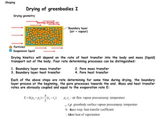
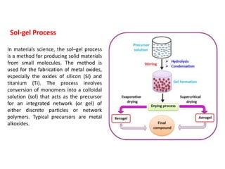
Processing of Ceramics
Sol-gel Process
In materials science, the sol–gel process
is a method for producing solid materials
from small molecules. The method is
used for the fabrication of metal oxides,
especially the oxides of silicon (Si) and
titanium (Ti). The process involves
conversion of monomers into a colloidal
solution (sol) that acts as the precursor
for an integrated network (or gel) of
either discrete particles or network
polymers. Typical precursors are metal
alkoxides.
Sol-gel Process
YBCO = YBa2Cu3O7-x
Synthesis of YBCO
SiO2 nanoparticles were synthesized by the
sol-gel method
at first 2 ml of TEOS is added to 5 ml of EtOH and stirred for
30 minutes, then another solution including HNO3 and EtOH is
added dropwise to the first solution and stirred for 2 hours at
60°C. The obtained opaque solution is heated in an oven at
100°C for 24 hours until the solvents are evaporated, then it
was calcinated in a furnace at 600°C for 4 hours and finally,
the SiO2 nanoparticles are obtained.
Flow chart of the hydrothermal process
Autoclave or
pressure
cooker needed
method product
geometry
Starting
material
mold costs product examples
axial die
pressing
simple-
complex
granulate high ferrite cores, piezo
ceramics
isostatic
pressing
simple granulate medium tubes, spark plug,
pistons
tape casting simple (tape) conc. suspension very low MLCCs, condensator
substrates
extrusion simple plastic mass low tubes
pressure slip
casting
simple conc. suspension low sanitary ceramics
slip casting complex conc. suspension low sanitary ceramics
injection molding complex plastic mass high turbine blades
Overview of shaping technologies
Shaping
• Compaction of granulates ca. 5%
• Extrusion, injection molding ca. 25-30
• Casting ca. 60-70%
increasing liquid
content
Liquid content of the starting material for the different shaping processes
Pressing
Shaping
Pressure forming methods
Compaction of powders is used for shaping simple forms.
uniaxial pressing
Compaction process:
1. sliding and rearrangement of particles/granules
2. Deformation (elastic and plastic) of
particles/granules
(3. Densification of granules)
Problems:
- Unhomogeneous density distribution
- Residual large pores (hollow granules)
- Ejection problems
Density
(%)
20
40
60
80
100
Pressure(Mpa)
20 40 60 80
alumina granules
tile body
KBr powder
Yanagida et al.: p. 158 - 160
The advantage of isostatic compaction is a more homogeneous density
distribution. The complexity of the mold is, however, limited.
Isostating pressing
Shaping
Green body
Pressure vessel
with liquid
Elastic, shape
stable form
Process flow diagram
for shaping by die pressing.
Shaping
Die pressing: flow chart
density
pressure
stage 1
stage 2
stage 3
Compaction behavior of granulated powders
stage I granule flow and rearrangement
stage II granule deformation
stage III granule densification
Shaping
Compaction of granules
End stage I End stage II
End stage III
Evolution of the green-body microstructure
during compaction of granules
Densification defects occurring on
die pressed green bodies.
Pressure distribution in a die at the
beginning and at the end of the second
compaction stage. The spring back behavior
after pressure is released is directly
proportional to the pressure in a certain
area. The differential pressure is mainly
due to friction of the punch.
Shaping
Densification defects
Die pressing additives
Reed, 1995
Shaping
Reed, 1995
Die pressing powders
Shaping
Products shaped
by axial die
pressing
Shaping
a) The slurry is poored into the
mold made of plaster of Paris
(CaSO4 0.5H2O). b) The mold
absorbs the liquid, while the
powder particles are deposited
on the walls of the mold. c)
The surplus suspension is
drained and d) the greenbody
is removed from the mold.
Slip casting I
Shaping
Steps in slip casting of ceramics. (Source: From
Modern Ceramic Engineering, by D.W. Richerson, p.
462, Fig. 10-34. Copyright © 1992 Marcel Dekker.
Reprinted by permission.)
Hollow molds
The holding time will dictate
the wall thickness of the
greenbody. Typical holding
times are between 5 and 30
minutes.
Shaping
Shaping
Slip casting of sanitary ceramics
Slip casting of porcellaine
250
500
750
1000
1250
1500
Viscosity
(mPa
sec)
0 20 40 60 80 100
spindle speed (rpm)
The rheology of the cast is shear
thinning. Before mixing, pumping
and pouring the slurry has to be
stirred
Rheology in slip casting
Shaping
Influence of the viscosity on the shape of
the slip casted white ware part
V
% sodium silicate
Rheology: the branch of physics that deals with the deformation and flow of matter, especially
the non-Newtonian flow of liquids and the plastic flow of solids.
Deflocculates: break up the floccules of (a
substance suspended in a liquid) into fine
particles, producing a dispersion
Kinetics of slip casting
Shaping
The thickness of the cake deposited
on the mold walls depend on mold and
suspension characteristics. The wall
thicknes growth is a parabolic.
Slip casted silicon nitride turbine
(Allied Signal)
Slip casting examples
Shaping
slurry
doctor blade
liquid absorbing, porous film
green body in form of a film
Compositions of a alumina and B.titanate tape cast (vol%)
Powder Al2O3 27.0 BaTiO3 28.0
Solvent Trichlorethylene 42.0 Methylethylketone 33.0
Ethylalcohol 16.0 Ethylalcolhol 16.0
Deflocculant Menhaden oil 1.8 Menhaden oil 1.7
Binder Polyvinylbutiral 4.4 Acryllic emulsion 6.7
Plasticizer Polyethylene glycol 4.8 Polyethylene glycol 6.7
Octyl phthalate 4.0 Butylbenzlphtalate 6.7
Wetting agent Cyclohexanone 1.2
Such slurries exhibit also shear thinning. The quality and thickness of the tape is controlled
by the size of the blade oppening, the speed of the tape, the rheology of the slurry and
the shrinkage during drying. Industrial tape casting machines are up to 25m long, several
meters wide and run with speeds. Up to 1.5m/min to produce tapes with thicknesses
between 25 and 1250mm.
Tape casting I
Shaping
A doctor blade assembly. The ceramic
slurry is held in the reservoir behind
the blade [middle of the micrograph].
The twin micrometers [right] control the
blade height above the carrier film.
More sophisticated versions feature
double blades and pumped metered
slurry flow to keep the height of the
slurry reservoir constant.
Example of a tape drying on the Mistler
laboratory-scale batch tape caster.
Industrially the process is often continuous
with the tape being force dried prior to
removal from the carrier, dicing and
further processing.
Tape casting II
Shaping
Pressurized slip casting I
Shaping
1. Closing of the mold 2. Injection of the slurry into the mold
Pressurized slip casting II
Shaping
3. Pressurizing the slurry 4. Draining of surplus slurry
Pressurized slip casting III
Shaping
5.Opening of the mold 6. Removal of the component
Pressurized slip casting mold for sinks
Pressurized slip casting examples
Shaping
Finished products
Process flow diagram
for shaping by
injection molding
Injection molding
Shaping
Injection molding products
Shaping
Most products shown in the picture are guiding elements used in thread manufacturing
slurry
cylindric greenbody
Yanagida et al.: p. 160
Industrial pug mill ith deairing chamber and extrusion auger
Extrusion casting
Shaping
Drying of greenbodies I
Boundary layer
(air + vapour)
Particles
Suspension liquid
moving drying air
Drying geometry
Drying kinetics will depend on the rate of heat transfer into the body and mass (liquid)
transport out of the body. Four rate determining processes can be distinguished:
1. Boundary layer mass transfer 2. Pore mass transfer
3. Boundary layer heat transfer 4. Pore heat transfer
Each of the above steps are rate determining for some time during drying, the boundary
layer process at the beginning, the pore processes towards the end. Mass and heat transfer
rates are obviously coupled and equal to the evaporation rate E:
E  k(pw  pa ) 
h
L
(tw  ta ) pa,ta : air flow vapour pressure,resp. temperature
p
w, tw : greenbody surface vapour pressure,
resp. temperature
k,
h: mass resp. heat transfer coefficient
L
: latent heat of vaporization
Shaping
time
Moisture
cont.
constant rate
decreasingt rate
Typincal drying curve
Drying of greenbodies II
as cast
Shrinkage and deformation
Moisture content at the surface const.
Rate determining step: heat and mass
transport through boundary layer
No further shrinkage, all particles
are in contact, leatherhard greenbody
completely dry
Partially filled pores. Rate determining
step: pore mass and heat transfer
The boundary processes are linear functions of the greenbody size (radius for spheres,
cylinders, thickness for plates), whereas the pore processes go with the square of the
greenbody dimension. The overall rate is ± a square function of the greenbody size.
Example for a spherical ZrO2 greenbody:
Diameter: drying time
1cm 5.8h
10cm 20 days
Shaping
Drying shrinkage
Linear and volume shrinkage of a greenbody can be defined by:

L
L0
 Nl
V
V0
1 1
L
L0






3
N :number of interparticle films per unit length
l: mean reduction of interparticle spacing
The shrinkage can be influenced by the moisture content (Dl) amd the particle dimensions (N)
moisture content
drying
rate
shrinkage
critical moist. cont.
shrinkage defects due to
1. Unhomogeneous drying of a homogeneous greenbody
2. Homogeneous drying of unhomogeneous green body
warping
cracking
Unhomogeneities: - uneven moisture distribution
- preferred orientation of particles
delamination
Shaping

07 8-lecture processing

  • 1.
  • 2.
    Sol-gel Process In materialsscience, the sol–gel process is a method for producing solid materials from small molecules. The method is used for the fabrication of metal oxides, especially the oxides of silicon (Si) and titanium (Ti). The process involves conversion of monomers into a colloidal solution (sol) that acts as the precursor for an integrated network (or gel) of either discrete particles or network polymers. Typical precursors are metal alkoxides.
  • 3.
  • 4.
  • 6.
    SiO2 nanoparticles weresynthesized by the sol-gel method at first 2 ml of TEOS is added to 5 ml of EtOH and stirred for 30 minutes, then another solution including HNO3 and EtOH is added dropwise to the first solution and stirred for 2 hours at 60°C. The obtained opaque solution is heated in an oven at 100°C for 24 hours until the solvents are evaporated, then it was calcinated in a furnace at 600°C for 4 hours and finally, the SiO2 nanoparticles are obtained.
  • 7.
    Flow chart ofthe hydrothermal process Autoclave or pressure cooker needed
  • 8.
    method product geometry Starting material mold costsproduct examples axial die pressing simple- complex granulate high ferrite cores, piezo ceramics isostatic pressing simple granulate medium tubes, spark plug, pistons tape casting simple (tape) conc. suspension very low MLCCs, condensator substrates extrusion simple plastic mass low tubes pressure slip casting simple conc. suspension low sanitary ceramics slip casting complex conc. suspension low sanitary ceramics injection molding complex plastic mass high turbine blades Overview of shaping technologies Shaping • Compaction of granulates ca. 5% • Extrusion, injection molding ca. 25-30 • Casting ca. 60-70% increasing liquid content Liquid content of the starting material for the different shaping processes
  • 9.
    Pressing Shaping Pressure forming methods Compactionof powders is used for shaping simple forms. uniaxial pressing Compaction process: 1. sliding and rearrangement of particles/granules 2. Deformation (elastic and plastic) of particles/granules (3. Densification of granules) Problems: - Unhomogeneous density distribution - Residual large pores (hollow granules) - Ejection problems Density (%) 20 40 60 80 100 Pressure(Mpa) 20 40 60 80 alumina granules tile body KBr powder Yanagida et al.: p. 158 - 160
  • 10.
    The advantage ofisostatic compaction is a more homogeneous density distribution. The complexity of the mold is, however, limited. Isostating pressing Shaping Green body Pressure vessel with liquid Elastic, shape stable form
  • 11.
    Process flow diagram forshaping by die pressing. Shaping Die pressing: flow chart
  • 12.
    density pressure stage 1 stage 2 stage3 Compaction behavior of granulated powders stage I granule flow and rearrangement stage II granule deformation stage III granule densification Shaping Compaction of granules End stage I End stage II End stage III Evolution of the green-body microstructure during compaction of granules
  • 13.
    Densification defects occurringon die pressed green bodies. Pressure distribution in a die at the beginning and at the end of the second compaction stage. The spring back behavior after pressure is released is directly proportional to the pressure in a certain area. The differential pressure is mainly due to friction of the punch. Shaping Densification defects
  • 14.
  • 15.
    Reed, 1995 Die pressingpowders Shaping
  • 16.
    Products shaped by axialdie pressing Shaping
  • 17.
    a) The slurryis poored into the mold made of plaster of Paris (CaSO4 0.5H2O). b) The mold absorbs the liquid, while the powder particles are deposited on the walls of the mold. c) The surplus suspension is drained and d) the greenbody is removed from the mold. Slip casting I Shaping Steps in slip casting of ceramics. (Source: From Modern Ceramic Engineering, by D.W. Richerson, p. 462, Fig. 10-34. Copyright © 1992 Marcel Dekker. Reprinted by permission.)
  • 19.
    Hollow molds The holdingtime will dictate the wall thickness of the greenbody. Typical holding times are between 5 and 30 minutes. Shaping
  • 20.
    Shaping Slip casting ofsanitary ceramics
  • 21.
    Slip casting ofporcellaine 250 500 750 1000 1250 1500 Viscosity (mPa sec) 0 20 40 60 80 100 spindle speed (rpm) The rheology of the cast is shear thinning. Before mixing, pumping and pouring the slurry has to be stirred Rheology in slip casting Shaping Influence of the viscosity on the shape of the slip casted white ware part V % sodium silicate Rheology: the branch of physics that deals with the deformation and flow of matter, especially the non-Newtonian flow of liquids and the plastic flow of solids. Deflocculates: break up the floccules of (a substance suspended in a liquid) into fine particles, producing a dispersion
  • 22.
    Kinetics of slipcasting Shaping The thickness of the cake deposited on the mold walls depend on mold and suspension characteristics. The wall thicknes growth is a parabolic.
  • 23.
    Slip casted siliconnitride turbine (Allied Signal) Slip casting examples Shaping
  • 24.
    slurry doctor blade liquid absorbing,porous film green body in form of a film Compositions of a alumina and B.titanate tape cast (vol%) Powder Al2O3 27.0 BaTiO3 28.0 Solvent Trichlorethylene 42.0 Methylethylketone 33.0 Ethylalcohol 16.0 Ethylalcolhol 16.0 Deflocculant Menhaden oil 1.8 Menhaden oil 1.7 Binder Polyvinylbutiral 4.4 Acryllic emulsion 6.7 Plasticizer Polyethylene glycol 4.8 Polyethylene glycol 6.7 Octyl phthalate 4.0 Butylbenzlphtalate 6.7 Wetting agent Cyclohexanone 1.2 Such slurries exhibit also shear thinning. The quality and thickness of the tape is controlled by the size of the blade oppening, the speed of the tape, the rheology of the slurry and the shrinkage during drying. Industrial tape casting machines are up to 25m long, several meters wide and run with speeds. Up to 1.5m/min to produce tapes with thicknesses between 25 and 1250mm. Tape casting I Shaping
  • 25.
    A doctor bladeassembly. The ceramic slurry is held in the reservoir behind the blade [middle of the micrograph]. The twin micrometers [right] control the blade height above the carrier film. More sophisticated versions feature double blades and pumped metered slurry flow to keep the height of the slurry reservoir constant. Example of a tape drying on the Mistler laboratory-scale batch tape caster. Industrially the process is often continuous with the tape being force dried prior to removal from the carrier, dicing and further processing. Tape casting II Shaping
  • 27.
    Pressurized slip castingI Shaping 1. Closing of the mold 2. Injection of the slurry into the mold
  • 28.
    Pressurized slip castingII Shaping 3. Pressurizing the slurry 4. Draining of surplus slurry
  • 29.
    Pressurized slip castingIII Shaping 5.Opening of the mold 6. Removal of the component
  • 30.
    Pressurized slip castingmold for sinks Pressurized slip casting examples Shaping Finished products
  • 31.
    Process flow diagram forshaping by injection molding Injection molding Shaping
  • 32.
    Injection molding products Shaping Mostproducts shown in the picture are guiding elements used in thread manufacturing
  • 33.
    slurry cylindric greenbody Yanagida etal.: p. 160 Industrial pug mill ith deairing chamber and extrusion auger Extrusion casting Shaping
  • 34.
    Drying of greenbodiesI Boundary layer (air + vapour) Particles Suspension liquid moving drying air Drying geometry Drying kinetics will depend on the rate of heat transfer into the body and mass (liquid) transport out of the body. Four rate determining processes can be distinguished: 1. Boundary layer mass transfer 2. Pore mass transfer 3. Boundary layer heat transfer 4. Pore heat transfer Each of the above steps are rate determining for some time during drying, the boundary layer process at the beginning, the pore processes towards the end. Mass and heat transfer rates are obviously coupled and equal to the evaporation rate E: E  k(pw  pa )  h L (tw  ta ) pa,ta : air flow vapour pressure,resp. temperature p w, tw : greenbody surface vapour pressure, resp. temperature k, h: mass resp. heat transfer coefficient L : latent heat of vaporization Shaping
  • 35.
    time Moisture cont. constant rate decreasingt rate Typincaldrying curve Drying of greenbodies II as cast Shrinkage and deformation Moisture content at the surface const. Rate determining step: heat and mass transport through boundary layer No further shrinkage, all particles are in contact, leatherhard greenbody completely dry Partially filled pores. Rate determining step: pore mass and heat transfer The boundary processes are linear functions of the greenbody size (radius for spheres, cylinders, thickness for plates), whereas the pore processes go with the square of the greenbody dimension. The overall rate is ± a square function of the greenbody size. Example for a spherical ZrO2 greenbody: Diameter: drying time 1cm 5.8h 10cm 20 days Shaping
  • 36.
    Drying shrinkage Linear andvolume shrinkage of a greenbody can be defined by:  L L0  Nl V V0 1 1 L L0       3 N :number of interparticle films per unit length l: mean reduction of interparticle spacing The shrinkage can be influenced by the moisture content (Dl) amd the particle dimensions (N) moisture content drying rate shrinkage critical moist. cont. shrinkage defects due to 1. Unhomogeneous drying of a homogeneous greenbody 2. Homogeneous drying of unhomogeneous green body warping cracking Unhomogeneities: - uneven moisture distribution - preferred orientation of particles delamination Shaping