Downloaded 633 times
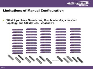
![Slide 17
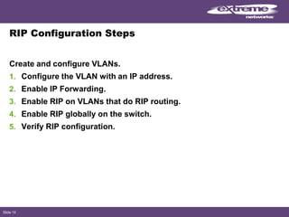
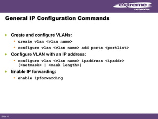
RIP Specific Configuration Commands
Enable RIP on VLANs that do RIP routing:
• configure rip add vlan [<vlan name> | all]
Enable RIP globally on the switch:
• enable rip
Disable RIP on VLANs:
• configure rip delete vlan [<vlan name> | all]
Disable RIP globally on the switch:
• disable rip
When RIP is disabled on the interface, the parameters are not reset
to their defaults.](https://image.slidesharecdn.com/module12rip-140409233901-phpapp02/85/RIP-Routing-Information-Protocol-Extreme-Networks-17-320.jpg)
![Slide 19
RIP Timer and Cost Configuration Commands
Configure RIP update timer:
• configure rip updatetime {<seconds>}
Configure RIP route timeout:
• configure rip routetimeout {<seconds>}
Configure RIP garbage time:
• configure rip garbagetime {<seconds>}
Configure RIP VLAN cost:
• configure rip vlan [<vlan name> | all] cost <cost>](https://image.slidesharecdn.com/module12rip-140409233901-phpapp02/85/RIP-Routing-Information-Protocol-Extreme-Networks-19-320.jpg)
![Slide 20
Additional RIP Configuration Commands
Configure RIP receive version:
• configure rip rxmode vlan [vlan name | all]
[none | v1only | v2only | any]
Configure RIP transmit version:
• configure rip txmode vlan [vlan name | all]
[none | v1only | v2only | any]
Enable or disable specific RIP features:
• [enable | disable] rip [aggregation | export |
|originate-default | poisonreverse | splithorizon |
triggerupdates | use-ip-router-alert]
Unconfigure RIP:
• unconfigure rip {vlan <vlan name>}](https://image.slidesharecdn.com/module12rip-140409233901-phpapp02/85/RIP-Routing-Information-Protocol-Extreme-Networks-20-320.jpg)
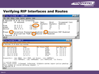
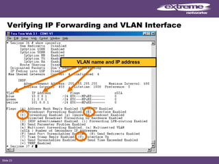
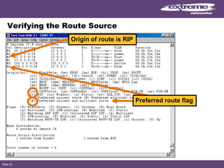
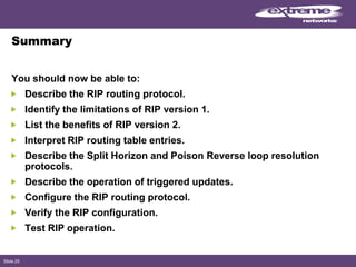


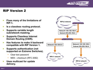
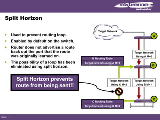
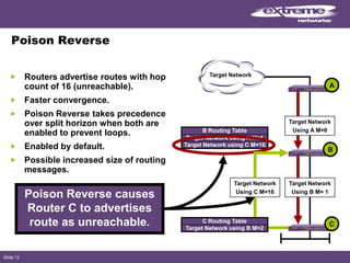
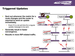
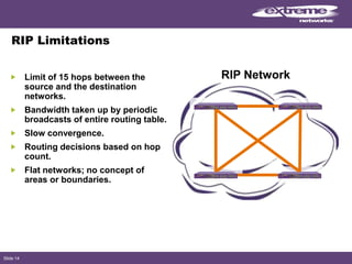
This document provides an overview of configuring the Routing Information Protocol (RIP) in ExtremeXOS. It describes RIP as a distance-vector routing protocol and discusses RIP version 1 and 2. The document outlines the steps to configure RIP, including enabling it on VLANs and globally, and verifies the RIP configuration. It also covers RIP concepts like routing loops, split horizon, poison reverse, and triggered updates. Students will learn how to configure, verify, and test RIP in the accompanying lab guide.