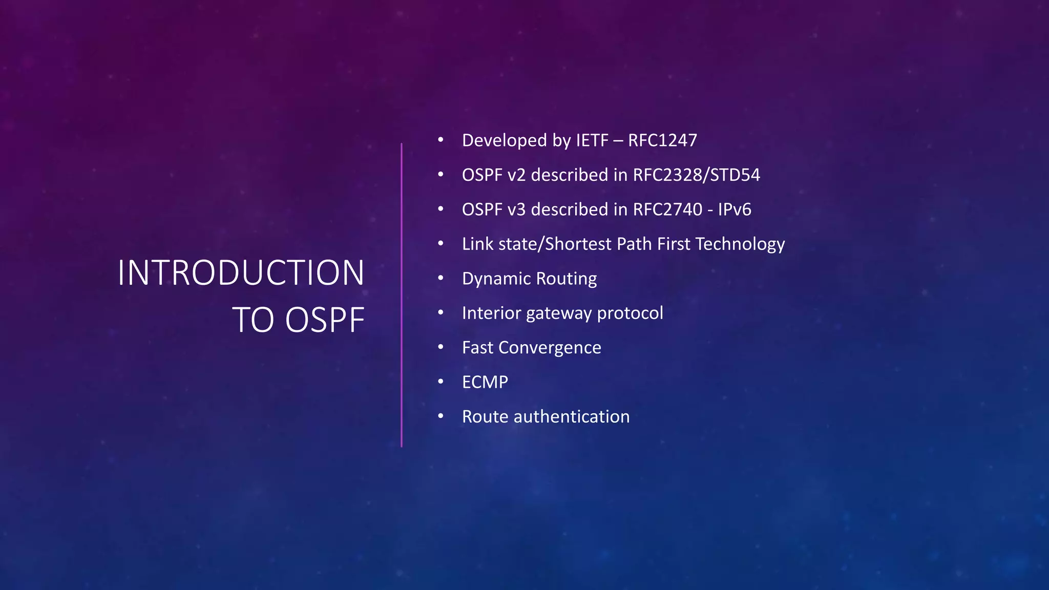
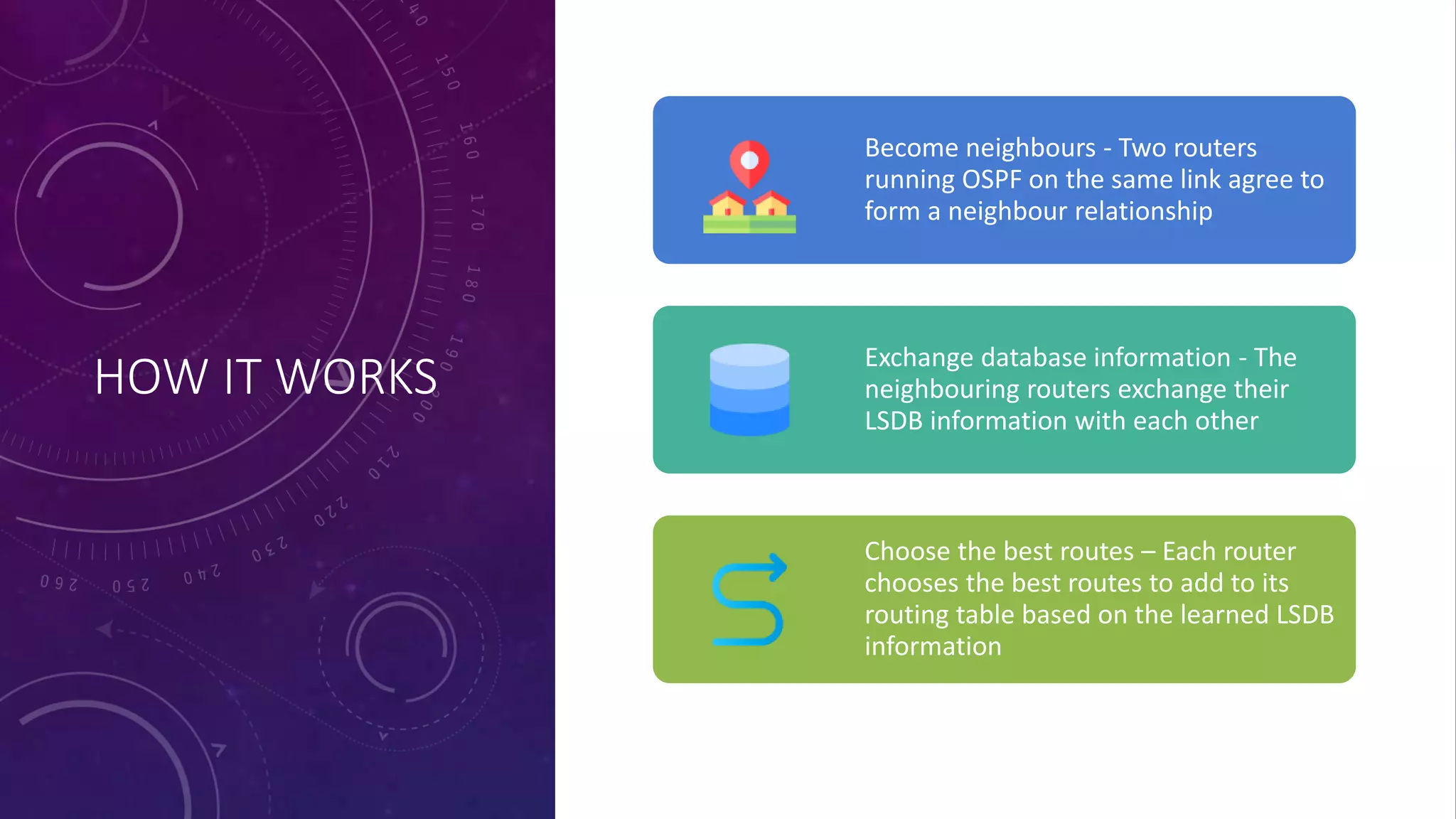
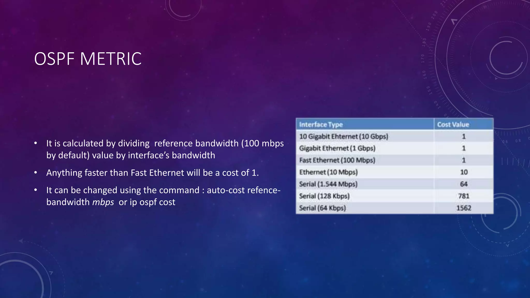
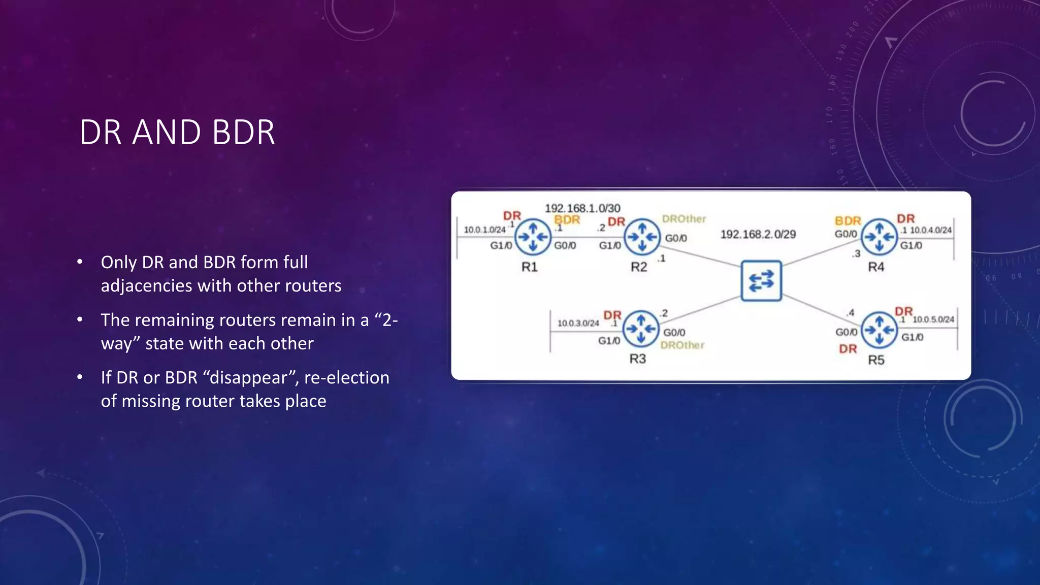
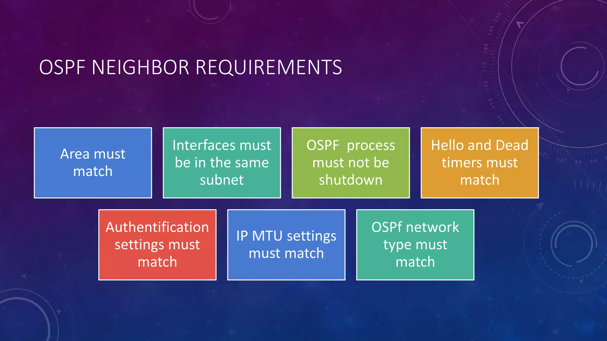
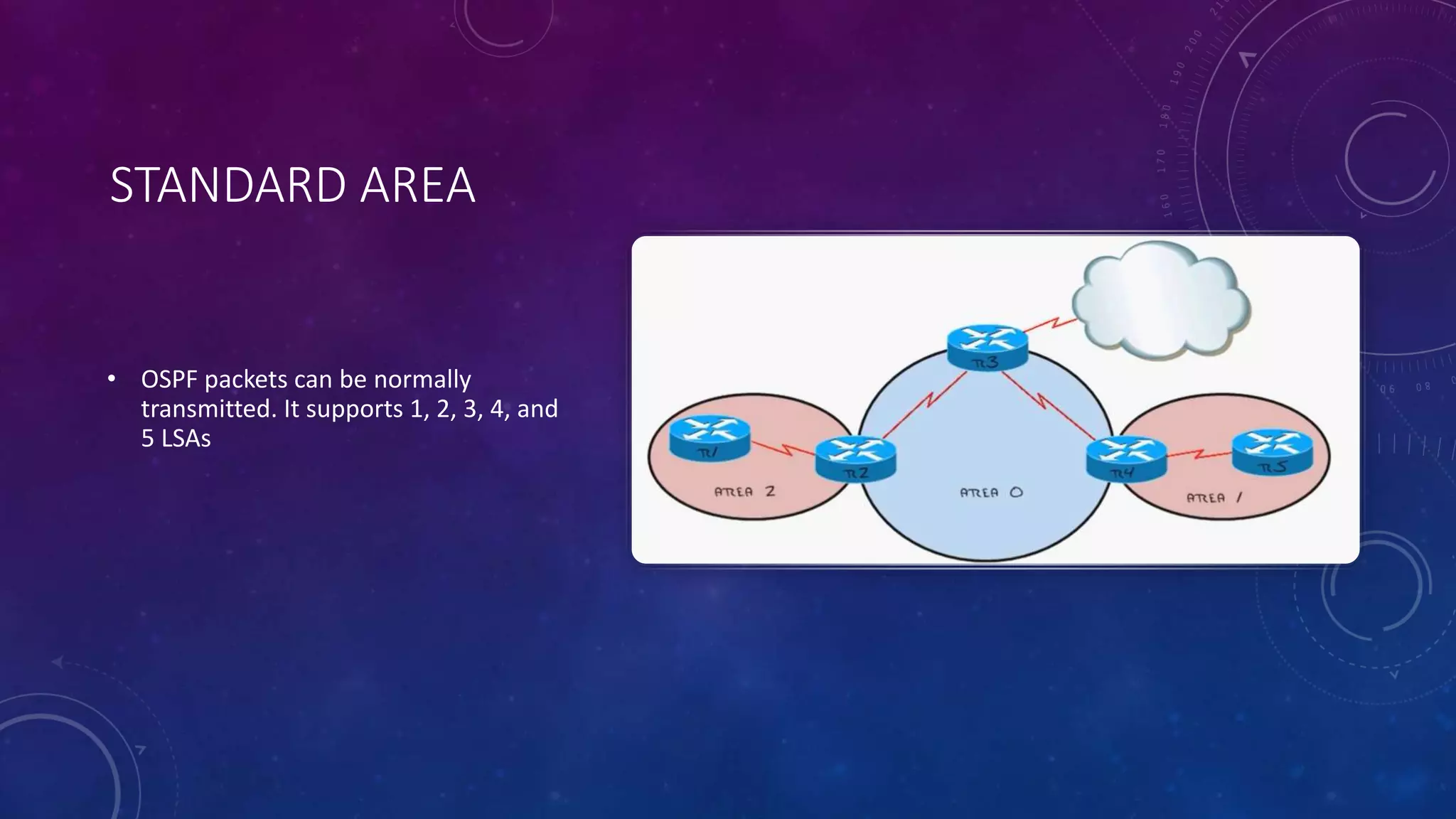
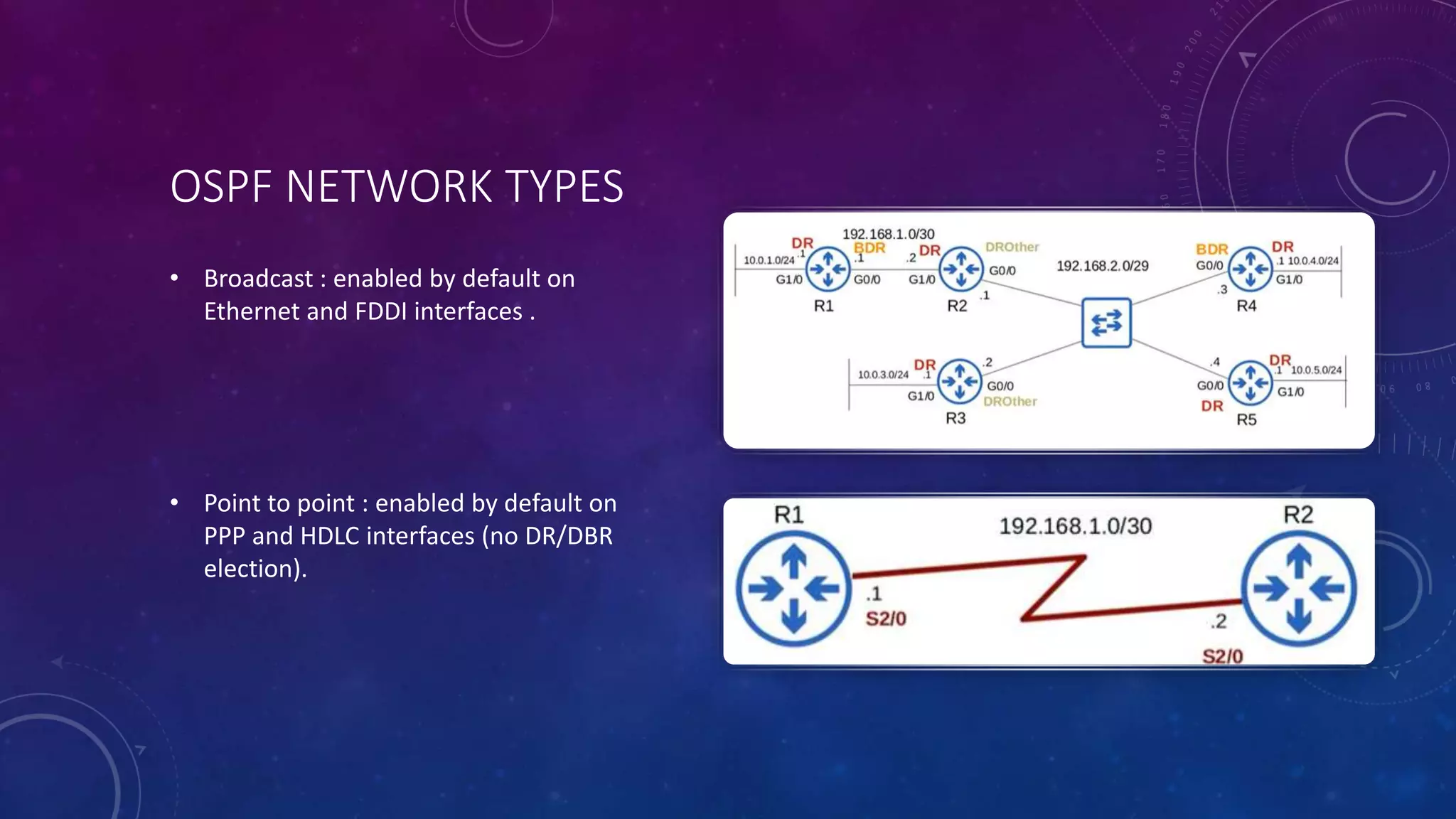
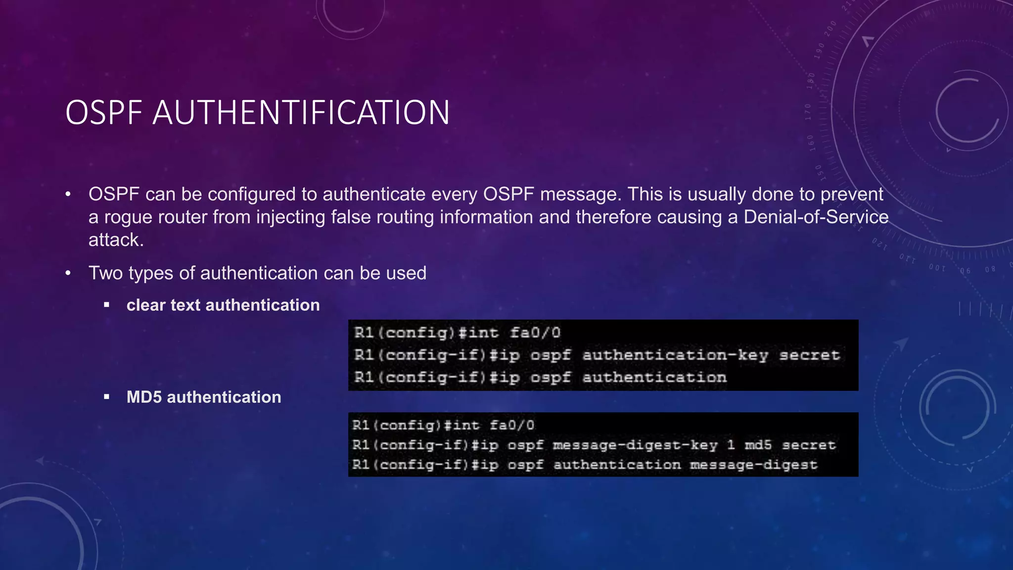
OSPF
ROUTING PROTOCOL
INTRODUCTION
TO OSPF
• Developed by IETF – RFC1247
• OSPF v2 described in RFC2328/STD54
• OSPF v3 described in RFC2740 - IPv6
• Link state/Shortest Path First Technology
• Dynamic Routing
• Interior gateway protocol
• Fast Convergence
• ECMP
• Route authentication
HOW IT WORKS
Become neighbours - Two routers
running OSPF on the same link agree to
form a neighbour relationship
Exchange database information - The
neighbouring routers exchange their
LSDB information with each other
Choose the best routes – Each router
chooses the best routes to add to its
routing table based on the learned LSDB
information
OSPF METRIC
• It is calculated by dividing reference bandwidth (100 mbps
by default) value by interface’s bandwidth
• Anything faster than Fast Ethernet will be a cost of 1.
• It can be changed using the command : auto-cost refence-
bandwidth mbps or ip ospf cost
ECMP
• Equal Cost Multi-Path or ECMP is a
routing strategy where packets
towards a single destination IP
address are load-balanced over
multiple best paths with equal
metrics.
HELLO MESSAGES
• When OSPF is activated on an interface , the router starts
sending OSPF hello messages out of the interface at regular
intervals (10 s by default)
• They are multicast to 224.0.0.5
• Dead timer - how long the router will wait without hearing a
HELLO message before it assumes the neighbor is dead (40 s
by default)
• The passive interface command tells the router to stop
sending OSPF HELLO messages out of the interface
LOOPBACK INTERFACE
• It is a virtual interface in the router .
• It is always up/up .
• It provides a consistent IP address that can be used to reach the router .
ROUTER ID
Mannually assigned
Highest Ip status loopback
interface Ip address
Highest Ip status non-
loopback interface Ip
address
OSPF NEIGHBORS
OSPF MESSAGES
DR AND BDR
• Only DR and BDR form full
adjacencies with other routers
• The remaining routers remain in a “2-
way” state with each other
• If DR or BDR “disappear”, re-election
of missing router takes place
OSPF NEIGHBOR REQUIREMENTS
Area must
match
Interfaces must
be in the same
subnet
OSPF process
must not be
shutdown
Hello and Dead
timers must
match
Authentification
settings must
match
IP MTU settings
must match
OSPf network
type must
match
OSPF AREAS
• It is uses to divide up the network
• Small networks can be single-areas without any negative effects on performance .
• In Larger networks , a single-area design can have negative effects :
 SFP algorithm takes more time to calculate routes
 Larger LSDB takes up memory
 Any small change in the network causes every router to flood LSAs and run the SPF algorithm again
• The backbone area is an area that all other areas must connect to .
CLASSIFICATION OF
ROUTERS
• Internal Router (IR)
• Area Border Router (ABR)
• Backbone Router (BR)
• Autonomous System Border Router
(ASBR)
LSA 1
• This LSA contains a list with all the directly
connected links of this route , it always
stays within the area
LSA 2
• The network LSA or type 2 is created
for each multi-access network ,
generated by the DR , In this LSA we
will find all the routers that are
connected to the multi-access
network, the DR and of course the
prefix and subnet mask , the network
LSA always stays within the area
LSA 3 SUMMARY
• This LSA generated by the ABR will
flood into all the other areas of our
OSPF network. This way all the
routers in other areas will know
about the prefixes from other areas.
TYPE 4 SUMMARY
ASBR LSA
• This LSA will also be flooded in all
other areas and is required so all
OSPF routers know where to find the
ASBR
LSA TYPE 5
• Generated by the ASBR to advertise
external redistributed routes into the
OSPF’s AS.
STANDARD AREA
• OSPF packets can be normally
transmitted. It supports 1, 2, 3, 4, and
5 LSAs
STUB AREA
• This area does not accept any
external routes of non-OSPF network
, this area supports 1, 2, and 3 LSAs
TOTALLY STUBBY
AREA
• this area does not accept external
routes and does not accept routes
from other areas , This area supports
Type 1, Type 2 LSAs, and Type 3 LSAs
with default routes
NO SO STUBBY AREA
• this mode allows the introduction of
external routes in a completely stub
area environment
OSPF NETWORK TYPES
• Broadcast : enabled by default on
Ethernet and FDDI interfaces .
• Point to point : enabled by default on
PPP and HDLC interfaces (no DR/DBR
election).
VIRTUAL LINK
• By using a virtual link, we can extend area
0 through area 1 so area 2 will be “directly
connected” to area 0
OSPF AUTHENTIFICATION
• OSPF can be configured to authenticate every OSPF message. This is usually done to prevent
a rogue router from injecting false routing information and therefore causing a Denial-of-Service
attack.
• Two types of authentication can be used
 clear text authentication
 MD5 authentication

OSPF - Copie.pptx

  • 1.
  • 2.
    INTRODUCTION TO OSPF • Developedby IETF – RFC1247 • OSPF v2 described in RFC2328/STD54 • OSPF v3 described in RFC2740 - IPv6 • Link state/Shortest Path First Technology • Dynamic Routing • Interior gateway protocol • Fast Convergence • ECMP • Route authentication
  • 3.
    HOW IT WORKS Becomeneighbours - Two routers running OSPF on the same link agree to form a neighbour relationship Exchange database information - The neighbouring routers exchange their LSDB information with each other Choose the best routes – Each router chooses the best routes to add to its routing table based on the learned LSDB information
  • 4.
    OSPF METRIC • Itis calculated by dividing reference bandwidth (100 mbps by default) value by interface’s bandwidth • Anything faster than Fast Ethernet will be a cost of 1. • It can be changed using the command : auto-cost refence- bandwidth mbps or ip ospf cost
  • 5.
    ECMP • Equal CostMulti-Path or ECMP is a routing strategy where packets towards a single destination IP address are load-balanced over multiple best paths with equal metrics.
  • 6.
    HELLO MESSAGES • WhenOSPF is activated on an interface , the router starts sending OSPF hello messages out of the interface at regular intervals (10 s by default) • They are multicast to 224.0.0.5 • Dead timer - how long the router will wait without hearing a HELLO message before it assumes the neighbor is dead (40 s by default) • The passive interface command tells the router to stop sending OSPF HELLO messages out of the interface
  • 7.
    LOOPBACK INTERFACE • Itis a virtual interface in the router . • It is always up/up . • It provides a consistent IP address that can be used to reach the router .
  • 8.
    ROUTER ID Mannually assigned HighestIp status loopback interface Ip address Highest Ip status non- loopback interface Ip address
  • 9.
  • 10.
  • 11.
    DR AND BDR •Only DR and BDR form full adjacencies with other routers • The remaining routers remain in a “2- way” state with each other • If DR or BDR “disappear”, re-election of missing router takes place
  • 12.
    OSPF NEIGHBOR REQUIREMENTS Areamust match Interfaces must be in the same subnet OSPF process must not be shutdown Hello and Dead timers must match Authentification settings must match IP MTU settings must match OSPf network type must match
  • 13.
    OSPF AREAS • Itis uses to divide up the network • Small networks can be single-areas without any negative effects on performance . • In Larger networks , a single-area design can have negative effects :  SFP algorithm takes more time to calculate routes  Larger LSDB takes up memory  Any small change in the network causes every router to flood LSAs and run the SPF algorithm again • The backbone area is an area that all other areas must connect to .
  • 14.
    CLASSIFICATION OF ROUTERS • InternalRouter (IR) • Area Border Router (ABR) • Backbone Router (BR) • Autonomous System Border Router (ASBR)
  • 15.
    LSA 1 • ThisLSA contains a list with all the directly connected links of this route , it always stays within the area
  • 16.
    LSA 2 • Thenetwork LSA or type 2 is created for each multi-access network , generated by the DR , In this LSA we will find all the routers that are connected to the multi-access network, the DR and of course the prefix and subnet mask , the network LSA always stays within the area
  • 17.
    LSA 3 SUMMARY •This LSA generated by the ABR will flood into all the other areas of our OSPF network. This way all the routers in other areas will know about the prefixes from other areas.
  • 18.
    TYPE 4 SUMMARY ASBRLSA • This LSA will also be flooded in all other areas and is required so all OSPF routers know where to find the ASBR
  • 19.
    LSA TYPE 5 •Generated by the ASBR to advertise external redistributed routes into the OSPF’s AS.
  • 20.
    STANDARD AREA • OSPFpackets can be normally transmitted. It supports 1, 2, 3, 4, and 5 LSAs
  • 21.
    STUB AREA • Thisarea does not accept any external routes of non-OSPF network , this area supports 1, 2, and 3 LSAs
  • 22.
    TOTALLY STUBBY AREA • thisarea does not accept external routes and does not accept routes from other areas , This area supports Type 1, Type 2 LSAs, and Type 3 LSAs with default routes
  • 23.
    NO SO STUBBYAREA • this mode allows the introduction of external routes in a completely stub area environment
  • 24.
    OSPF NETWORK TYPES •Broadcast : enabled by default on Ethernet and FDDI interfaces . • Point to point : enabled by default on PPP and HDLC interfaces (no DR/DBR election).
  • 25.
    VIRTUAL LINK • Byusing a virtual link, we can extend area 0 through area 1 so area 2 will be “directly connected” to area 0
  • 26.
    OSPF AUTHENTIFICATION • OSPFcan be configured to authenticate every OSPF message. This is usually done to prevent a rogue router from injecting false routing information and therefore causing a Denial-of-Service attack. • Two types of authentication can be used  clear text authentication  MD5 authentication