Downloaded 57 times

This lecture notes present an overview of computer organization, focusing on von Neumann and Harvard architectures, along with the roles of Memory Address Register (MAR) and Memory Data Register (MDR) in CPU instruction execution. It discusses the steps for executing instructions, differences between Complex Instruction Set Computers (CISC) and Reduced Instruction Set Computers (RISC), along with their respective features and performance characteristics. The document emphasizes the trends in computer architecture, highlighting the integration of best features from both CISC and RISC for optimal performance.
Introduction to computer organization subject by R S Ananda Murthy, focusing on architecture.
Specific outcomes include understanding Von Neumann and Harvard architecture, MAR, MDR functions, instruction execution steps, and CISC vs RISC features.
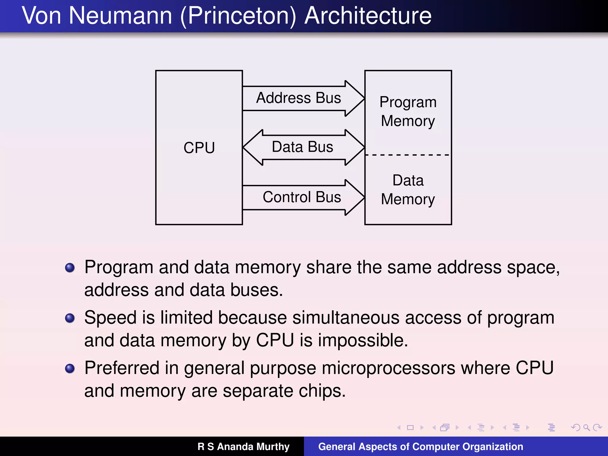
Describes CPU, memory connections, buses, and limitations of simultaneous data access in Von Neumann architecture.
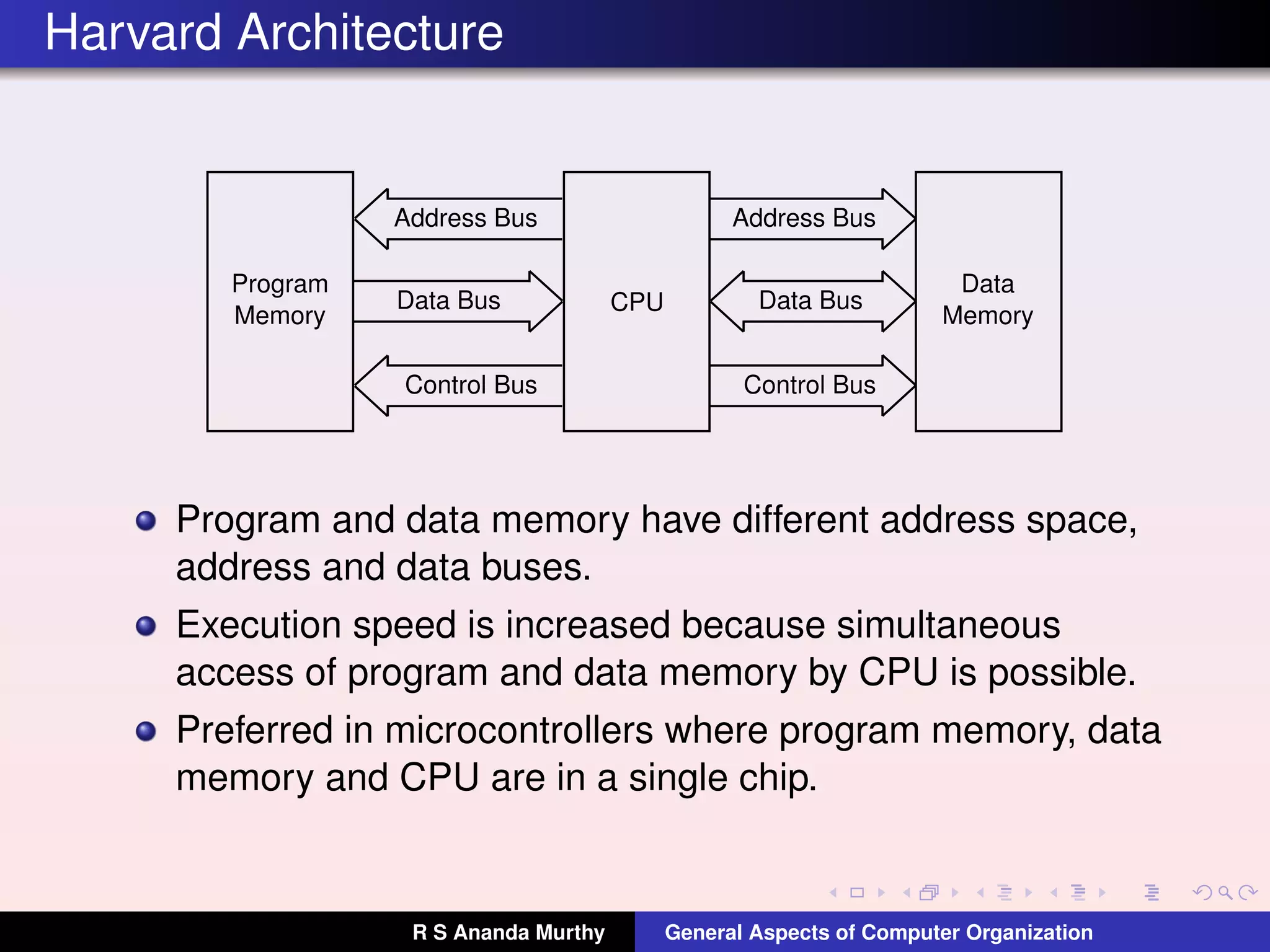
Highlights structure of Harvard architecture, including separate memory spaces for programs and data, improving execution speed.
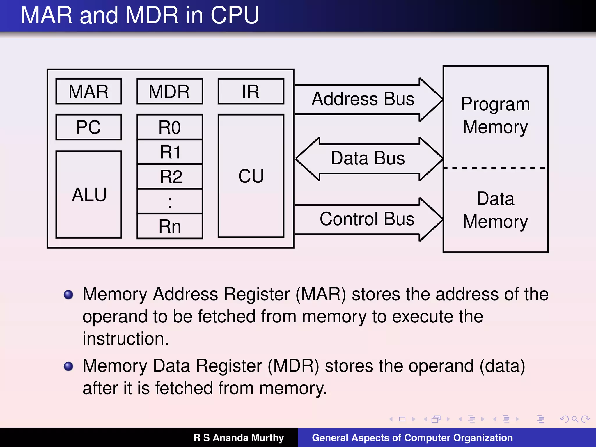
Explanation of Memory Address Register and Memory Data Register roles in storing memory addresses and data.
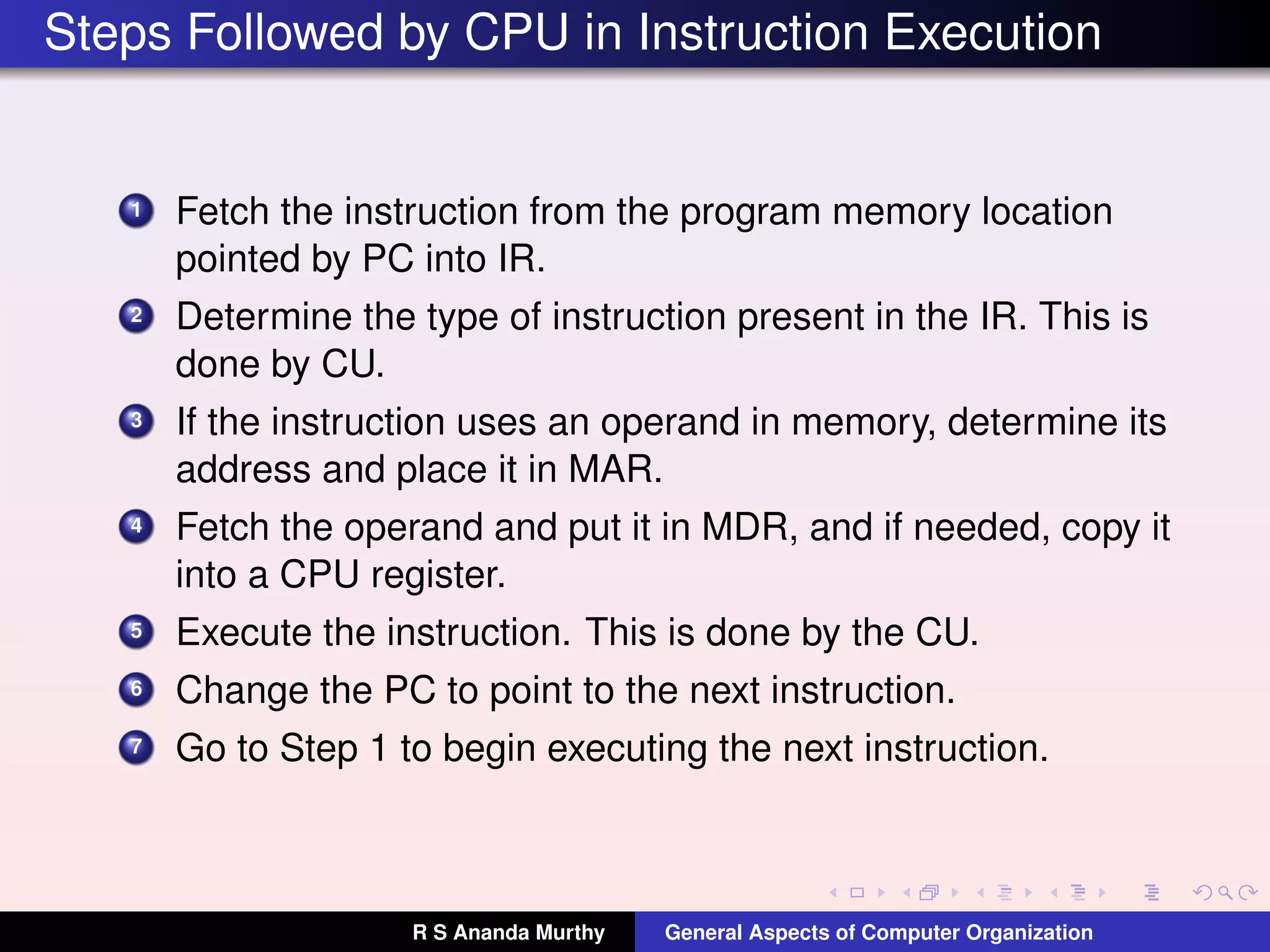
Detailed steps for CPU instruction execution from fetching to changing the program counter.
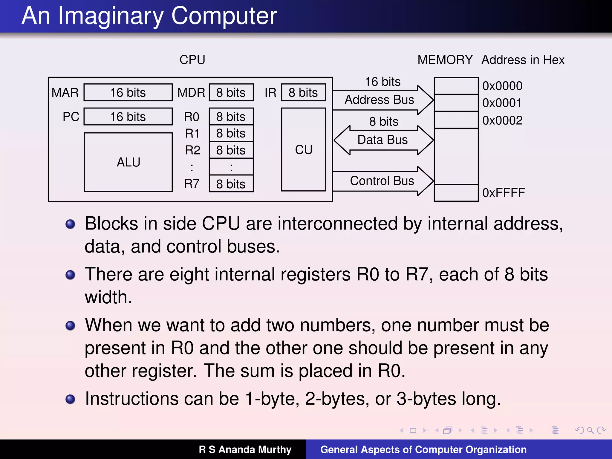
Description of components in an imaginary CPU, bus connections, and details of register setup.
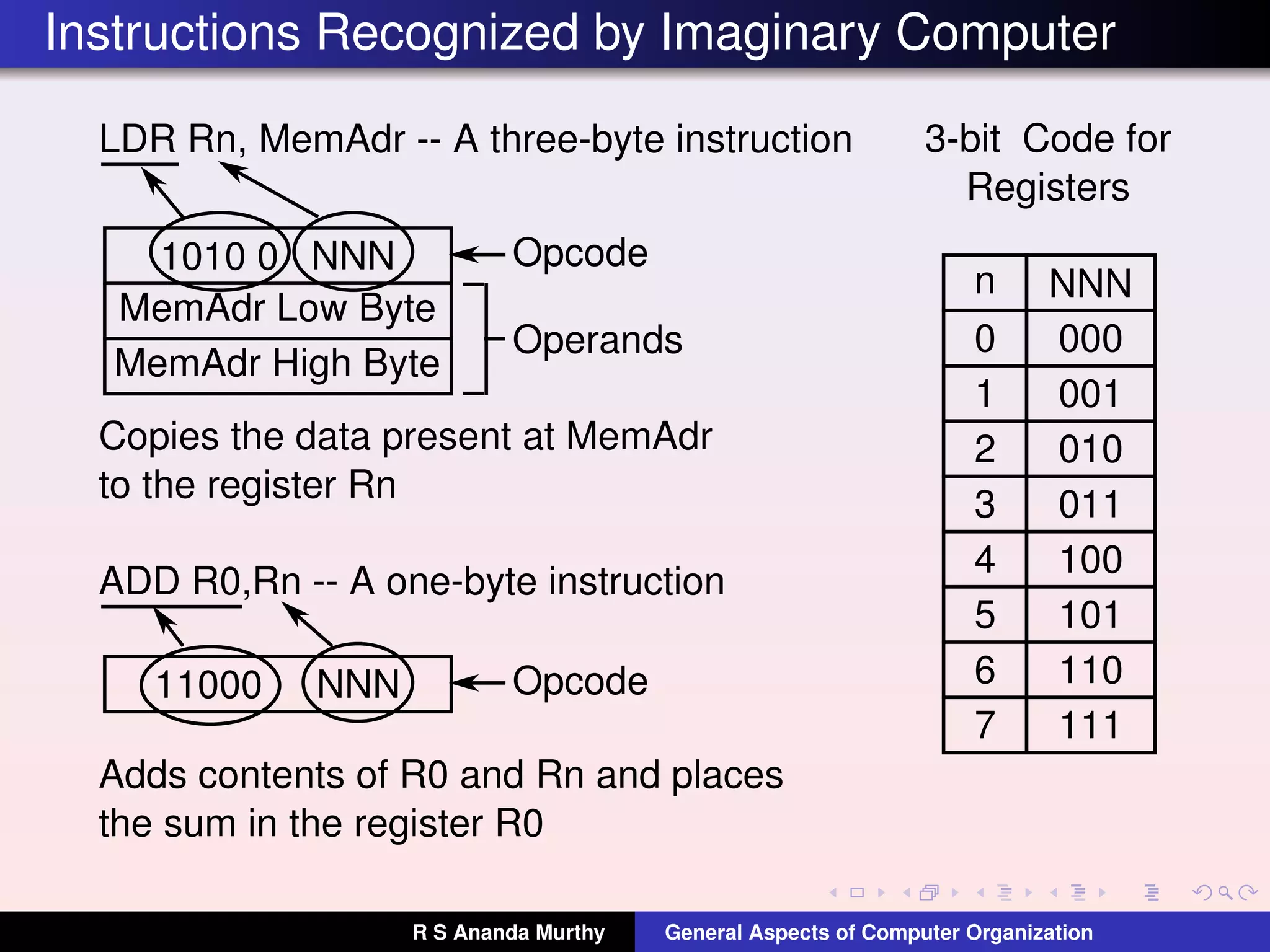
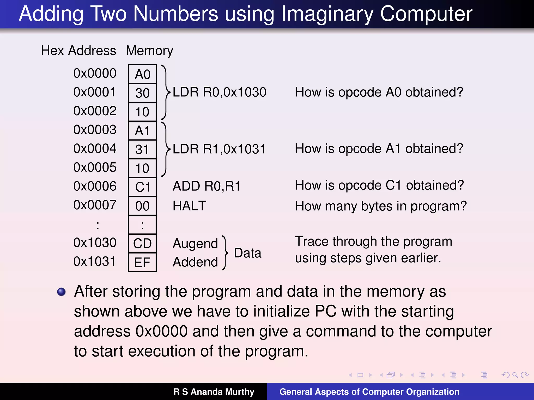
Examples of instruction formats like LDR and ADD in the imaginary computer, detailing opcodes and function.
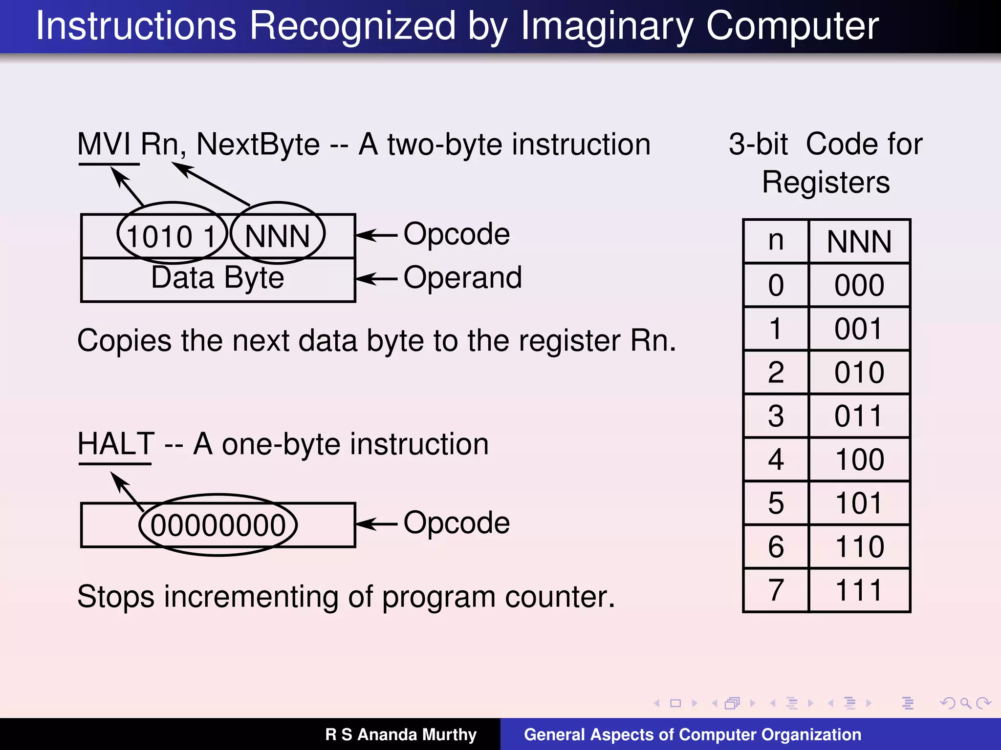
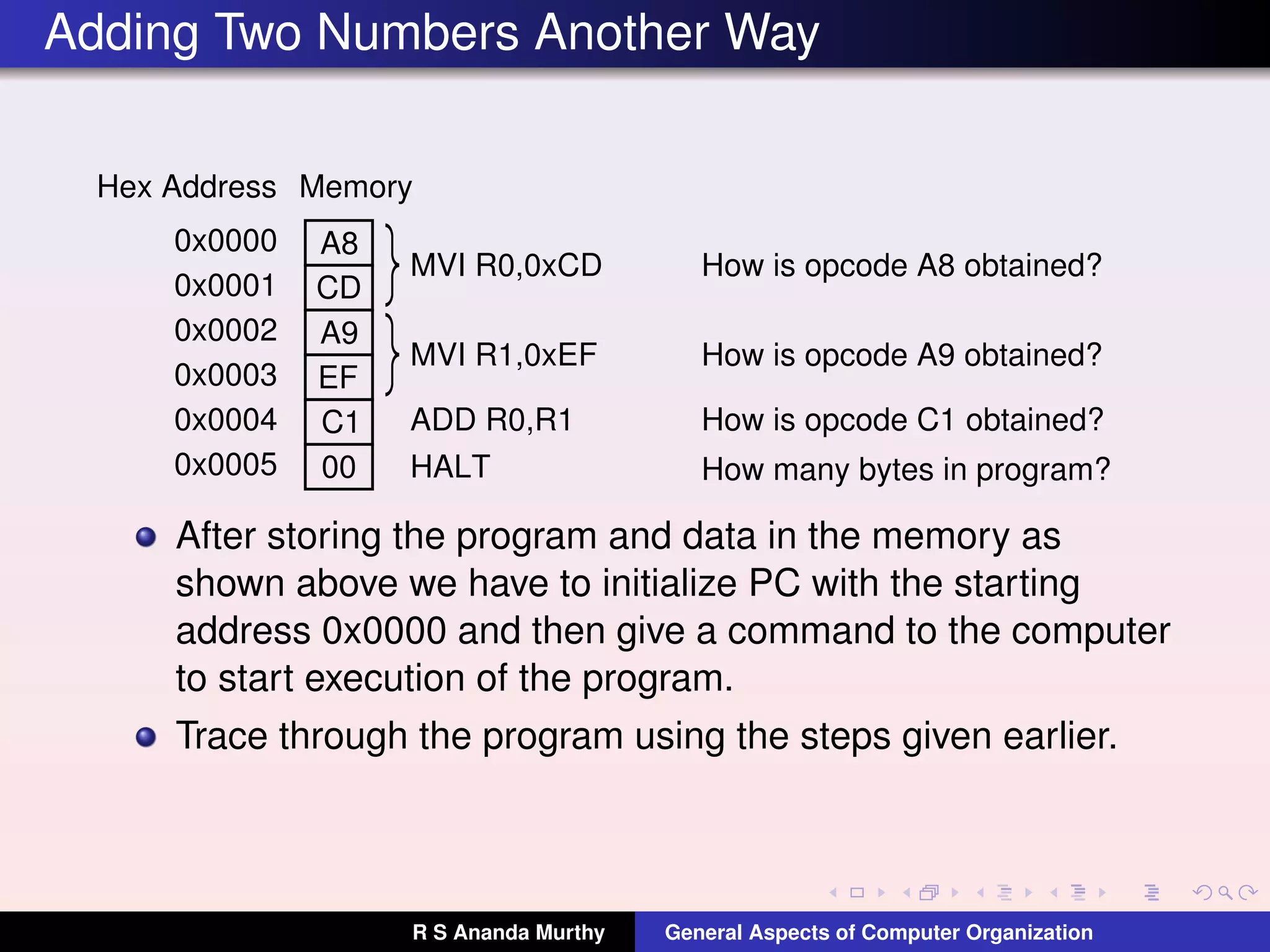
Additional instruction formats like MVI and HALT, with focus on their operations and encoding.
Demonstration of program structure to add numbers, including memory setup and sequential instruction execution.
Another method to add two numbers with similar initialization and operational tracking.
Classification of computers into CISC and RISC based on instruction types and execution approaches.
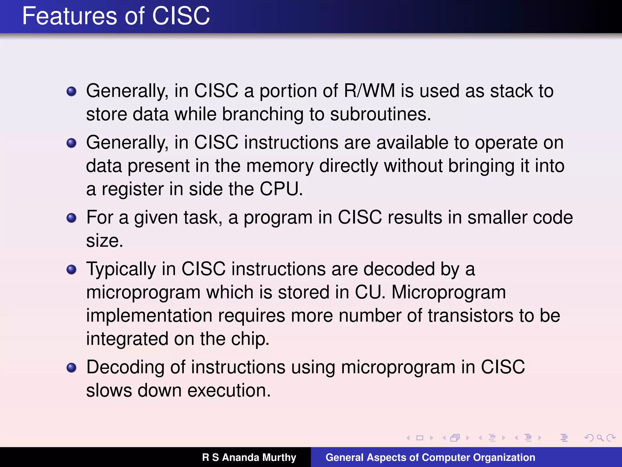
Characteristics of CISC architecture including instruction variety, execution duration, and memory use.
Further exploration of data handling and instruction decoding methods in CISC architectures.
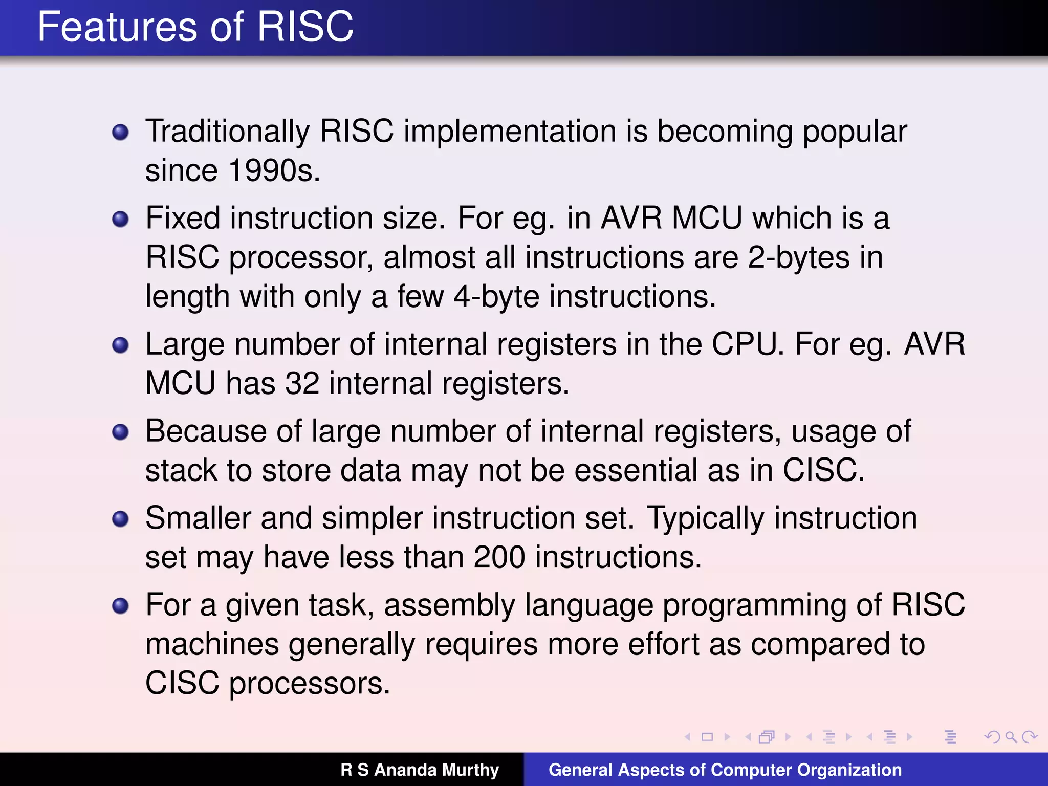
Highlights properties of RISC, including fixed instruction size, register use, and programming implications.
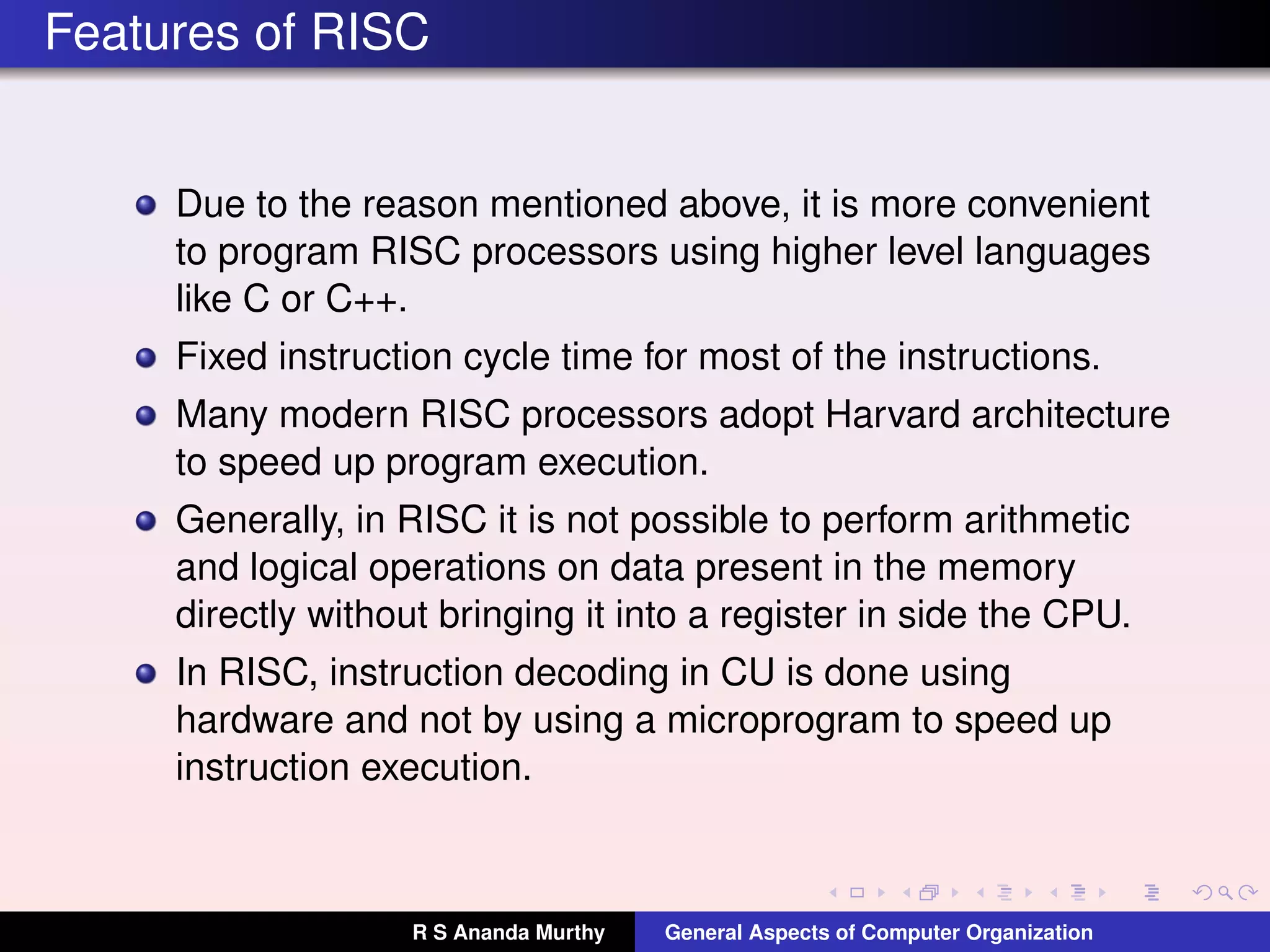
Discusses RISC's advantages in programming with higher-level languages, fixed instruction times, and hardware decoding.
Details regarding the licensing of the work under Creative Commons Attribution 4.0 International License.