• The CentralProcessing Unit (CPU) is the heart of a
computer system.
• The CPU along with the memory and the I/O sub-systems
develops a powerful computer system.
• comprises of three major components
Register Set, ALU and Control Unit
Introduction
3.
Register Set
•The register set comprises many registers which include general
purpose registers and special purpose registers.
• The general purpose registers store the temporary data that is required
by a program.
• The special purpose registers perform specific functions for the CPU.
Example: Instruction Register (IR) is a special purpose register that
stores the instruction that is currently being executed.
ALU
• The ALU performs all the arithmetic, logical, and shift operations by
providing necessary circuitry that supports these computations.
Control Unit The control unit fetches the instructions from the main
memory, decodes the instructions, and then executes it.
Introduction
4.
• Hardwired systemsare inflexible
• General purpose hardware can do different tasks, given correct
control signals
• Instead of re-wiring, supply a new set of control signals
Program Concept
5.
• A sequenceof steps
• For each step, an arithmetic or logical
operation is done
• For each operation, a different set of control
signals is needed
What is a program?
6.
Function of ControlUnit
• For each operation a unique code is
provided
—e.g. ADD, MOVE
• A hardware segment accepts the code and
issues the control signals
• We have a computer!
7.
Components
• The ControlUnit and the Arithmetic and
Logic Unit constitute the Central
Processing Unit
• Data and instructions need to get into the
system and results out
—Input/output
• Temporary storage of code and results is
needed
—Main memory
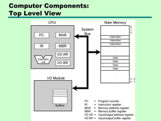
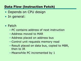
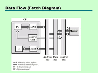
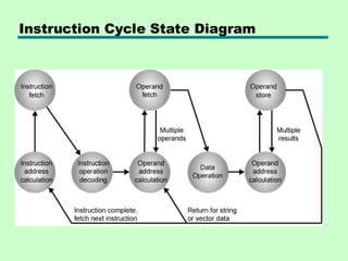
Data Flow (InstructionFetch)
• Depends on CPU design
• In general:
• Fetch
—PC contains address of next instruction
—Address moved to MAR
—Address placed on address bus
—Control unit requests memory read
—Result placed on data bus, copied to MBR,
then to IR
—Meanwhile PC incremented by 1
10.
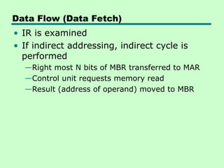
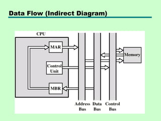
Data Flow (DataFetch)
• IR is examined
• If indirect addressing, indirect cycle is
performed
—Right most N bits of MBR transferred to MAR
—Control unit requests memory read
—Result (address of operand) moved to MBR
Data Flow (Execute)
•May take many forms
• Depends on instruction being executed
• May include
—Memory read/write
—Input/Output
—Register transfers
—ALU operations
14.
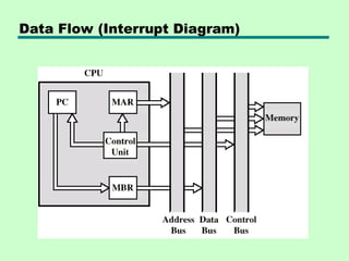
Data Flow (Interrupt)
•Simple
• Predictable
• Current PC saved to allow resumption
after interrupt
• Contents of PC copied to MBR
• Special memory location (e.g. stack
pointer) loaded to MAR
• MBR written to memory
• PC loaded with address of interrupt
handling routine
• Next instruction (first of interrupt handler)
can be fetched
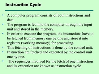
• A computerprogram consists of both instructions and
data.
• The program is fed into the computer through the input
unit and stored in the memory.
• In order to execute the program, the instructions have to
be fetched from memory one by one and store it into
registers (working memory) for processing.
• This fetching of instructions is done by the control unit.
• Instruction are fetched and executed by the control unit
one by one.
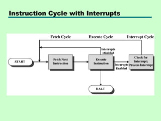
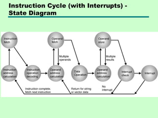
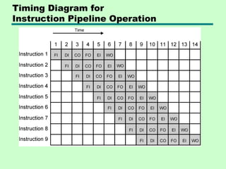
• The sequences involved for the fetch of one instruction
and its execution are known as instruction cycle
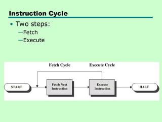
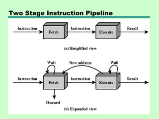
Instruction Cycle
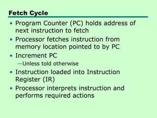
Fetch Cycle
• ProgramCounter (PC) holds address of
next instruction to fetch
• Processor fetches instruction from
memory location pointed to by PC
• Increment PC
—Unless told otherwise
• Instruction loaded into Instruction
Register (IR)
• Processor interprets instruction and
performs required actions
19.
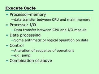
Execute Cycle
• Processor-memory
—datatransfer between CPU and main memory
• Processor I/O
—Data transfer between CPU and I/O module
• Data processing
—Some arithmetic or logical operation on data
• Control
—Alteration of sequence of operations
—e.g. jump
• Combination of above
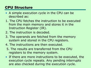
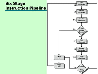
CPU Structure
• Asimple execution cycle in the CPU can be
described as:
1. The CPU fetches the instruction to be executed
from the main memory and stores it in the
Instruction Register (IR).
2. The instruction is decoded.
3. The operands are fetched from the memory
system and stored in the CPU registers.
4. The instructions are then executed.
5. The results are transferred from the CPU
registers to the memory system.
• If there are more instructions to be executed, the
execution cycle repeats. Any pending interrupts
are also checked during the execution cycle.
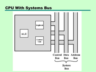
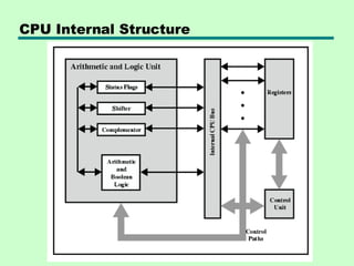
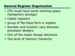
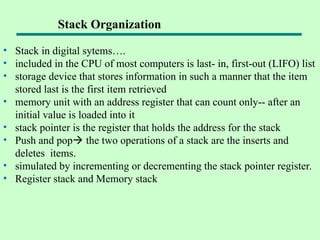
General Register Organization
•CPU must have some working space
(temporary storage)
• Called registers
• group of flip-flops form a register
• Number and function vary between
processor designs
• One of the major design decisions
• Top level of memory hierarchy
General Purpose Registers(1)
• May be true general purpose
• May be restricted
• May be used for data or addressing
• Data
—Accumulator
• Addressing
—Segment
28.
General Purpose Registers(2)
• Make them general purpose
—Increase flexibility and programmer options
—Increase instruction size & complexity
• Make them specialized
—Smaller (faster) instructions
—Less flexibility
29.
How Many GPRegisters?
• Between 8 - 32
• Fewer = more memory references
• More does not reduce memory references
and takes up processor real estate
• See also RISC
30.
How big?
• Largeenough to hold full address
• Large enough to hold full word
• Often possible to combine two data
registers
—C programming
—double int a;
—long int a;
31.
Condition Code Registers
•Sets of individual bits
—e.g. result of last operation was zero
• Can be read (implicitly) by programs
—e.g. Jump if zero
• Can not (usually) be set by programs
32.
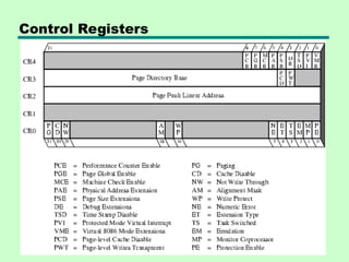
Control & StatusRegisters
• Program Counter
• Instruction Decoding Register
• Memory Address Register
• Memory Buffer Register
• Revision: what do these all do?
33.
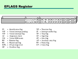
Program Status Word
•A set of bits
• Includes Condition Codes
• Sign of last result
• Zero
• Carry
• Equal
• Overflow
• Interrupt enable/disable
• Supervisor
34.
Supervisor Mode
• Intelring zero
• Kernel mode
• Allows privileged instructions to execute
• Used by operating system
• Not available to user programs
35.
Other Registers
• Mayhave registers pointing to:
—Process control blocks (see O/S)
—Interrupt Vectors (see O/S)
• N.B. CPU design and operating system
design are closely linked
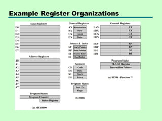
Stack Organization
• Stackin digital sytems….
• included in the CPU of most computers is last- in, first-out (LIFO) list
• storage device that stores information in such a manner that the item
stored last is the first item retrieved
• memory unit with an address register that can count only-- after an
initial value is loaded into it
• stack pointer is the register that holds the address for the stack
• Push and pop the two operations of a stack are the inserts and
deletes items.
• simulated by incrementing or decrementing the stack pointer register.
• Register stack and Memory stack
38.
Instruction Format
• Instructionformat in computer architecture
defines how bits in a CPU instruction are
organized into fields
• operation code (opcode), operands and
addressing mode
• The binary layout or structure of a machine-level
instruction that dictates how the instruction is
decoded by the CPU
• The main types are zero-address, one-address,
two-address, and three-address formats,
differing in how many operands they explicitly
specify, which impacts machine complexity and
instruction length
39.
• The bitsof an instruction are divided into
fields, with each field specifying a
different component of the command.
• Think of it as a template or blueprint for
all the machine language instructions for a
particular computer architecture
Instruction format
40.
Components of anInstruction Format
•Opcode (Operation Code): Specifies the operation to be performed,
such as ADD, SUB, LOAD, or STORE.
•Operand References: Specifies the data (operands) on which the
operation is to be performed.
•This can be a value, a register, or a memory address.
•Addressing Mode: Specifies how the address of an operand is
determined.
•Visual Element: A simple block diagram showing the main fields of
a generic instruction.
•[ Opcode | Addressing Mode | Operand Address ]
• Instruction Length:The total number of bits per instruction. Varies
between fixed-length (RISC) and variable-length (CISC)
architectures.
• Number of Operands: Fewer addresses in the instruction lead to
more instructions for a given task.
• Addressing Modes: The number and complexity of supported
addressing modes impact the instruction format.
• Memory Organization: How memory is structured and addressed
(e.g., byte-addressable vs. word-addressable).
• Number of CPU Registers: How many registers are available and
addressable.
• In general, Instruction formats are fundamental to computer
architecture, determining how the CPU interprets and executes
commands. The choice of format (zero, one, two, or three-address)
reflects a trade-off between instruction length and program length.
Factors Influencing Instruction Format
43.
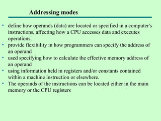
• define howoperands (data) are located or specified in a computer's
instructions, affecting how a CPU accesses data and executes
operations.
• provide flexibility in how programmers can specify the address of
an operand
• used specifying how to calculate the effective memory address of
an operand
• using information held in registers and/or constants contained
within a machine instruction or elsewhere.
• The operands of the instructions can be located either in the main
memory or the CPU registers
Addressing modes
44.
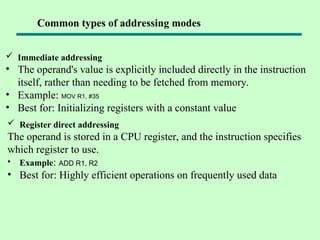
Immediate addressing
•The operand's value is explicitly included directly in the instruction
itself, rather than needing to be fetched from memory.
• Example: MOV R1, #35
• Best for: Initializing registers with a constant value
Common types of addressing modes
Register direct addressing
The operand is stored in a CPU register, and the instruction specifies
which register to use.
• Example: ADD R1, R2
• Best for: Highly efficient operations on frequently used data
45.
Direct (orabsolute) addressing
• The instruction contains the operand's effective memory address.
• The CPU goes directly to this address to fetch the data.
• Example: LOAD R1, 1000H
• Best for: Accessing static data, such as fixed variables.
Indirect addressing
• The instruction's address field points to a memory location or
register that holds the effective address of the operand.
• Example: ADD R1, [1000H]
• Best for: Implementing pointers, as the pointer's address is
known, but the data it points to can change
Common types of addressing modes
46.
Register indirectaddressing
• Similar to indirect addressing, but the register contains the effective
• address of the operand. This is faster than memory-based indirect
addressing because registers are faster to access.
• Example: LOAD R1, (R2)
• Best for: Implementing pointers and iterating through arrays
Indexed addressing
• The effective address is calculated by adding a constant value
(displacement) to the contents of an index register.
• Example: ADD R1, TABLE1[R2]
• Best for: Efficiently accessing elements in an array or list
Common types of addressing modes
47.
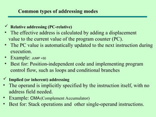
Relative addressing(PC-relative)
• The effective address is calculated by adding a displacement
value to the current value of the program counter (PC).
• The PC value is automatically updated to the next instruction during
execution.
• Example: JUMP +50
• Best for: Position-independent code and implementing program
control flow, such as loops and conditional branches
Implied (or inherent) addressing
• The operand is implicitly specified by the instruction itself, with no
address field needed.
• Example: CMA(Complement Accumulator)
• Best for: Stack operations and other single-operand instructions.
Common types of addressing modes
48.
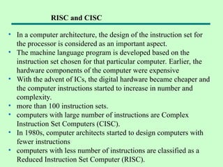
• In acomputer architecture, the design of the instruction set for
the processor is considered as an important aspect.
• The machine language program is developed based on the
instruction set chosen for that particular computer. Earlier, the
hardware components of the computer were expensive
• With the advent of ICs, the digital hardware became cheaper and
the computer instructions started to increase in number and
complexity.
• more than 100 instruction sets.
• computers with large number of instructions are Complex
Instruction Set Computers (CISC).
• In 1980s, computer architects started to design computers with
fewer instructions
• computers with less number of instructions are classified as a
Reduced Instruction Set Computer (RISC).
RISC and CISC
49.
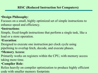
•Design Philosophy:
Focuses ona small, highly optimized set of simple instructions to
enhance speed and efficiency.
•Instructions:
Simple, fixed-length instructions that perform a single task, like a
load or a store operation.
•Execution:
Designed to execute one instruction per clock cycle using
pipelining to overlap fetch, decode, and execute phases.
•Memory Access:
Primarily works on registers within the CPU, with memory access
taking more time.
•Compiler Role:
Relies heavily on compiler optimization to produce highly efficient
code with smaller memory footprints
RISC (Reduced Instruction Set Computers)
50.
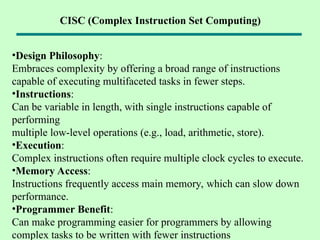
•Design Philosophy:
Embraces complexityby offering a broad range of instructions
capable of executing multifaceted tasks in fewer steps.
•Instructions:
Can be variable in length, with single instructions capable of
performing
multiple low-level operations (e.g., load, arithmetic, store).
•Execution:
Complex instructions often require multiple clock cycles to execute.
•Memory Access:
Instructions frequently access main memory, which can slow down
performance.
•Programmer Benefit:
Can make programming easier for programmers by allowing
complex tasks to be written with fewer instructions
CISC (Complex Instruction Set Computing)
51.
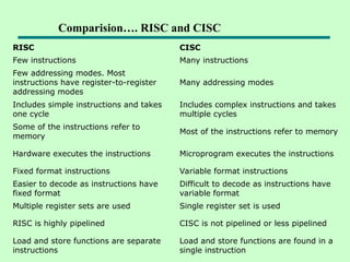
RISC CISC
Few instructionsMany instructions
Few addressing modes. Most
instructions have register-to-register
addressing modes
Many addressing modes
Includes simple instructions and takes
one cycle
Includes complex instructions and takes
multiple cycles
Some of the instructions refer to
memory
Most of the instructions refer to memory
Hardware executes the instructions Microprogram executes the instructions
Fixed format instructions Variable format instructions
Easier to decode as instructions have
fixed format
Difficult to decode as instructions have
variable format
Multiple register sets are used Single register set is used
RISC is highly pipelined CISC is not pipelined or less pipelined
Load and store functions are separate
instructions
Load and store functions are found in a
single instruction
Comparision…. RISC and CISC
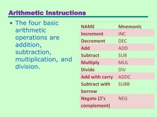
Data Transfer andManipulation
Most computer instructions can be
classified into three categories:
1) Data transfer,
2) Data manipulation,
3) Program control instructions
54.
Data Transfer Instruction
Datatransfer instructions move data from
one place in the computer to another
without changing the data content
The most common transfers are between
memory and processor registers, between
processor registers and input or output,
and between the processor registers
themselves.
55.
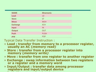
Typical Data TransferInstruction :
» Load : transfer from memory to a processor register,
usually an AC (memory read)
» Store : transfer from a processor register into
memory (memory write)
» Move : transfer from one register to another register
» Exchange : swap information between two registers
or a register and a memory word
» Input/Output : transfer data among processor
registers and input/output device
NAME Mnemonic
Load LD
Store ST
Move MOV
Exchange XCH
Input IN
Output OUT
Push PUSH
pop POP
56.
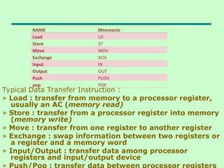
Typical Data TransferInstruction :
» Load : transfer from memory to a processor register,
usually an AC (memory read)
» Store : transfer from a processor register into memory
(memory write)
» Move : transfer from one register to another register
» Exchange : swap information between two registers or
a register and a memory word
» Input/Output : transfer data among processor
registers and input/output device
» Push/Pop : transfer data between processor registers
NAME Mnemonic
Load LD
Store ST
Move MOV
Exchange XCH
Input IN
Output OUT
Push PUSH
pop POP
57.
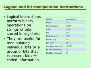
Data Manipulation Instruction
DataManipulation Instructions perform
operations on data and provide the
computational capabilities for the
computer.
It is divided into three basic types:
1) Arithmetic,
2) Logical and bit manipulation,
3) Shift Instruction
Logical and bitmanipulation Instructions
NAME Mnemonic
Clear CLR
Complement COM
AND AND
OR OR
Exclusive-or XOR
Clear carry CLRC
Set carry SETC
complement carry COMC
Enable interrupt EI
Disable interrupt DI
60.
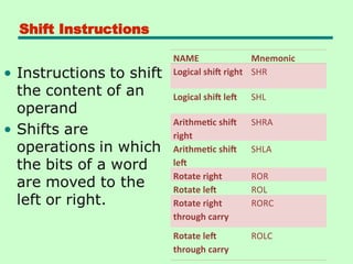
Shift Instructions
NAME Mnemonic
Logicalshift right SHR
Logical shift left SHL
Arithmetic shift
right
SHRA
Arithmetic shift
left
SHLA
Rotate right ROR
Rotate left ROL
Rotate right
through carry
RORC
Rotate left
through carry
ROLC
61.
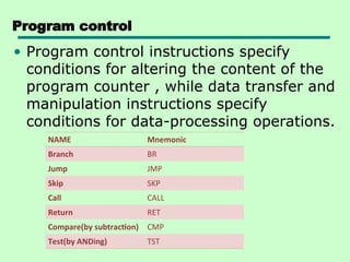
Program control
• Programcontrol instructions specify
conditions for altering the content of the
program counter , while data transfer and
manipulation instructions specify
conditions for data-processing operations.
NAME Mnemonic
Branch BR
Jump JMP
Skip SKP
Call CALL
Return RET
Compare(by subtraction) CMP
Test(by ANDing) TST
62.
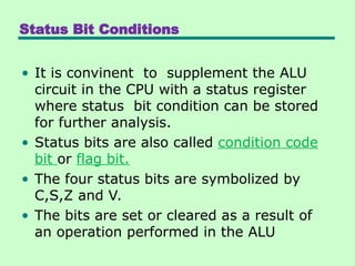
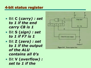
Status Bit Conditions
•It is convinent to supplement the ALU
circuit in the CPU with a status register
where status bit condition can be stored
for further analysis.
• Status bits are also called condition code
bit or flag bit.
• The four status bits are symbolized by
C,S,Z and V.
• The bits are set or cleared as a result of
an operation performed in the ALU
Subroutine Call andReturn
It is a self-contained sequence of
instructions that performs a given
computational task.
During the execution of a program,a
subroutine may call when it is called, a
branch is executed to the beginning of the
subroutine to start executing its set of
instructions. After the subroutine has been
executed,a branch is made back to the
main program.
66.
A subroutinecall is implemented with the
following microoperations:
CALL:
SP SP-1
← : Decrement stack point
M[SP] PC
← : Push content of PC onto
the stack
PC←Effective Address : Transfer control
to the subroutine
RETURN:
PC M[SP]
← : Pop stack and transfer to
PC
SP SP+1
← : Increment stack pointer
67.
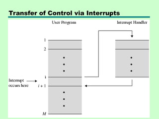
Program Interrupt
» Transferprogram control from a currently
running program to another service
program as a result of an external or
internal generated request
» Control returns to the original program
after the service program is executed
68.
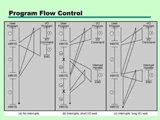
Interrupts
• Mechanism bywhich other modules (e.g.
I/O) may interrupt normal sequence of
processing
• Program
—e.g. overflow, division by zero
• Timer
—Generated by internal processor timer
—Used in pre-emptive multi-tasking
• I/O
—from I/O controller
• Hardware failure
—e.g. memory parity error
69.
Types of Interrupts
1)External Interrupts
» come from I/O device, from a timing
device, from a circuit monitoring the power
supply, or from any other external source
2) Internal Interrupts or TRAP
» caused by register overflow, attempt to
divide by zero, an invalid operation code,
stack overflow, and protection violation
3) Software Interrupts
» initiated by executing an instruction (INT
or RST)
» used by the programmer to initiate an
interrupt procedure at any desired point in
the program
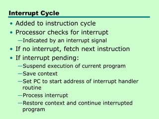
Interrupt Cycle
• Addedto instruction cycle
• Processor checks for interrupt
—Indicated by an interrupt signal
• If no interrupt, fetch next instruction
• If interrupt pending:
—Suspend execution of current program
—Save context
—Set PC to start address of interrupt handler
routine
—Process interrupt
—Restore context and continue interrupted
program
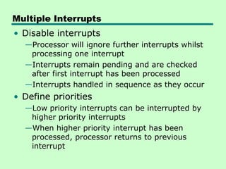
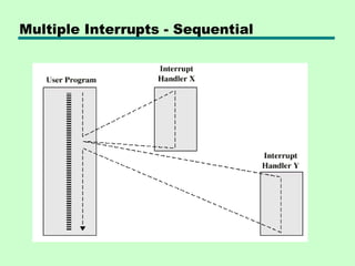
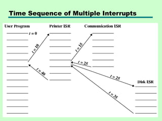
Multiple Interrupts
• Disableinterrupts
—Processor will ignore further interrupts whilst
processing one interrupt
—Interrupts remain pending and are checked
after first interrupt has been processed
—Interrupts handled in sequence as they occur
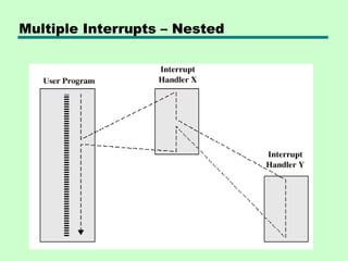
• Define priorities
—Low priority interrupts can be interrupted by
higher priority interrupts
—When higher priority interrupt has been
processed, processor returns to previous
interrupt
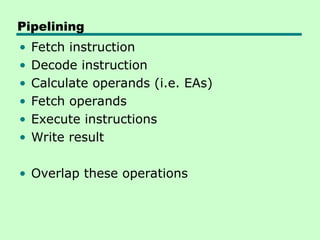
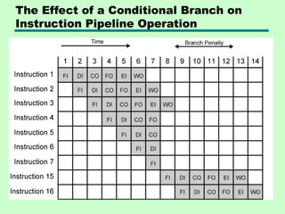
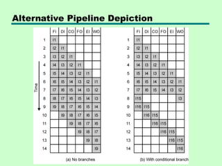
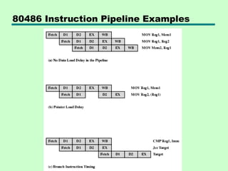
Prefetch
• Fetch accessingmain memory
• Execution usually does not access main
memory
• Can fetch next instruction during
execution of current instruction
• Called instruction prefetch
82.
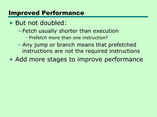
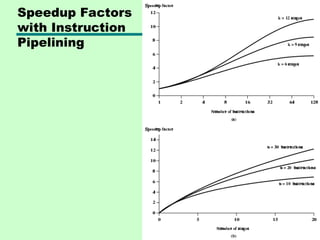
Improved Performance
• Butnot doubled:
—Fetch usually shorter than execution
– Prefetch more than one instruction?
—Any jump or branch means that prefetched
instructions are not the required instructions
• Add more stages to improve performance
Pipeline Hazards
• Pipeline,or some portion of pipeline, must
stall
• Also called pipeline bubble
• Types of hazards
—Resource
—Data
—Control
91.
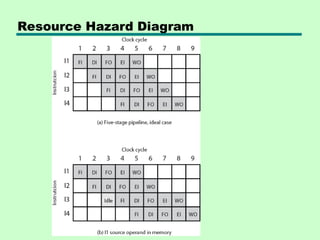
Resource Hazards
• Two(or more) instructions in pipeline need same resource
• Executed in serial rather than parallel for part of pipeline
• Also called structural hazard
• E.g. Assume simplified five-stage pipeline
— Each stage takes one clock cycle
• Ideal case is new instruction enters pipeline each clock cycle
• Assume main memory has single port
• Assume instruction fetches and data reads and writes performed
one at a time
• Ignore the cache
• Operand read or write cannot be performed in parallel with
instruction fetch
• Fetch instruction stage must idle for one cycle fetching I3
• E.g. multiple instructions ready to enter execute instruction phase
• Single ALU
• One solution: increase available resources
— Multiple main memory ports
— Multiple ALUs
92.
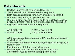
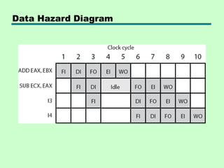
Data Hazards
• Conflictin access of an operand location
• Two instructions to be executed in sequence
• Both access a particular memory or register operand
• If in strict sequence, no problem occurs
• If in a pipeline, operand value could be updated so as to
produce different result from strict sequential execution
• E.g. x86 machine instruction sequence:
• ADD EAX, EBX /* EAX = EAX + EBX
• SUB ECX, EAX /* ECX = ECX – EAX
• ADD instruction does not update EAX until end of stage 5,
at clock cycle 5
• SUB instruction needs value at beginning of its stage 2, at
clock cycle 4
• Pipeline must stall for two clocks cycles
• Without special hardware and specific avoidance
algorithms, results in inefficient pipeline usage
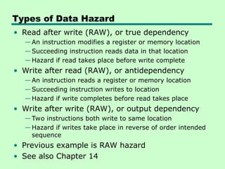
Types of DataHazard
• Read after write (RAW), or true dependency
—An instruction modifies a register or memory location
—Succeeding instruction reads data in that location
—Hazard if read takes place before write complete
• Write after read (RAW), or antidependency
—An instruction reads a register or memory location
—Succeeding instruction writes to location
—Hazard if write completes before read takes place
• Write after write (RAW), or output dependency
—Two instructions both write to same location
—Hazard if writes take place in reverse of order intended
sequence
• Previous example is RAW hazard
• See also Chapter 14
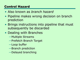
Control Hazard
• Alsoknown as branch hazard
• Pipeline makes wrong decision on branch
prediction
• Brings instructions into pipeline that must
subsequently be discarded
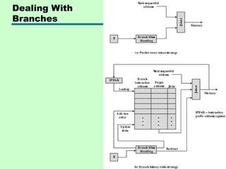
• Dealing with Branches
—Multiple Streams
—Prefetch Branch Target
—Loop buffer
—Branch prediction
—Delayed branching
97.
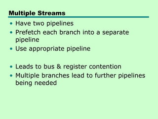
Multiple Streams
• Havetwo pipelines
• Prefetch each branch into a separate
pipeline
• Use appropriate pipeline
• Leads to bus & register contention
• Multiple branches lead to further pipelines
being needed
98.
Prefetch Branch Target
•Target of branch is prefetched in addition
to instructions following branch
• Keep target until branch is executed
• Used by IBM 360/91
99.
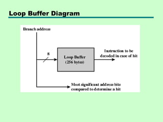
Loop Buffer
• Veryfast memory
• Maintained by fetch stage of pipeline
• Check buffer before fetching from memory
• Very good for small loops or jumps
• c.f. cache
• Used by CRAY-1
Branch Prediction (1)
•Predict never taken
—Assume that jump will not happen
—Always fetch next instruction
—68020 & VAX 11/780
—VAX will not prefetch after branch if a page
fault would result (O/S v CPU design)
• Predict always taken
—Assume that jump will happen
—Always fetch target instruction
102.
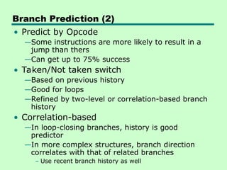
Branch Prediction (2)
•Predict by Opcode
—Some instructions are more likely to result in a
jump than thers
—Can get up to 75% success
• Taken/Not taken switch
—Based on previous history
—Good for loops
—Refined by two-level or correlation-based branch
history
• Correlation-based
—In loop-closing branches, history is good
predictor
—In more complex structures, branch direction
correlates with that of related branches
– Use recent branch history as well
103.
Branch Prediction (3)
•Delayed Branch
—Do not take jump until you have to
—Rearrange instructions
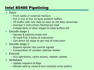
Intel 80486 Pipelining
•Fetch
— From cache or external memory
— Put in one of two 16-byte prefetch buffers
— Fill buffer with new data as soon as old data consumed
— Average 5 instructions fetched per load
— Independent of other stages to keep buffers full
• Decode stage 1
— Opcode & address-mode info
— At most first 3 bytes of instruction
— Can direct D2 stage to get rest of instruction
• Decode stage 2
— Expand opcode into control signals
— Computation of complex address modes
• Execute
— ALU operations, cache access, register update
• Writeback
— Update registers & flags
— Results sent to cache & bus interface write buffers
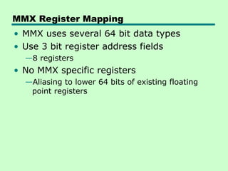
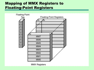
MMX Register Mapping
•MMX uses several 64 bit data types
• Use 3 bit register address fields
—8 registers
• No MMX specific registers
—Aliasing to lower 64 bits of existing floating
point registers
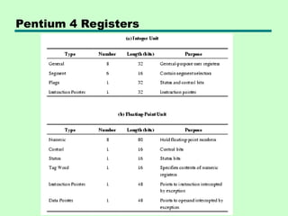
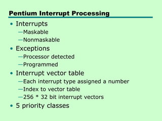
Pentium Interrupt Processing
•Interrupts
—Maskable
—Nonmaskable
• Exceptions
—Processor detected
—Programmed
• Interrupt vector table
—Each interrupt type assigned a number
—Index to vector table
—256 * 32 bit interrupt vectors
• 5 priority classes
115.
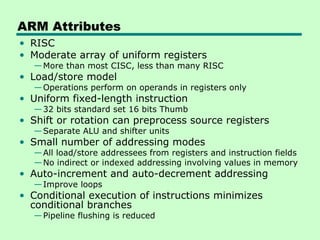
ARM Attributes
• RISC
•Moderate array of uniform registers
—More than most CISC, less than many RISC
• Load/store model
—Operations perform on operands in registers only
• Uniform fixed-length instruction
—32 bits standard set 16 bits Thumb
• Shift or rotation can preprocess source registers
—Separate ALU and shifter units
• Small number of addressing modes
—All load/store addressees from registers and instruction fields
—No indirect or indexed addressing involving values in memory
• Auto-increment and auto-decrement addressing
—Improve loops
• Conditional execution of instructions minimizes
conditional branches
—Pipeline flushing is reduced
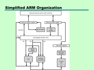
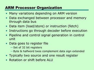
ARM Processor Organization
•Many variations depending on ARM version
• Data exchanged between processor and memory
through data bus
• Data item (load/store) or instruction (fetch)
• Instructions go through decoder before execution
• Pipeline and control signal generation in control
unit
• Data goes to register file
—Set of 32 bit registers
—Byte & halfword twos complement data sign extended
• Typically two source and one result register
• Rotation or shift before ALU
118.
ARM Processor Modes
•User
• Privileged
—6 modes
– OS can tailor systems software use
– Some registers dedicated to each privileged mode
– Swifter context changes
• Exception
—5 of privileged modes
—Entered on given exceptions
—Substitute some registers for user registers
– Avoid corruption
119.
Privileged Modes
• SystemMode
— Not exception
— Uses same registers as User mode
— Can be interrupted by…
• Supervisor mode
— OS
— Software interrupt usedd to invoke operating system services
• Abort mode
— memory faults
• Undefined mode
— Attempt instruction that is not supported by integer core
coprocessors
• Fast interrupt mode
— Interrupt signal from designated fast interrupt source
— Fast interrupt cannot be interrupted
— May interrupt normal interrupt
• Interrupt mode
• Interrupt signal from any other interrupt source
ARM Register Organization
•37 x 32-bit registers
• 31 general-purpose registers
—Some have special purposes
—E.g. program counters
• Six program status registers
• Registers in partially overlapping banks
—Processor mode determines bank
• 16 numbered registers and one or two
program status registers visible
122.
General Register Usage
•R13 normally stack pointer (SP)
—Each exception mode has its own R13
• R14 link register (LR)
—Subroutine and exception mode return
address
• R15 program counter
123.
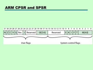
CPSR
• CPSR processstatus register
—Exception modes have dedicated SPSR
• 16 msb are user flags
—Condition codes (N,Z,C,V)
—Q – overflow or saturation in some SMID
instructions
—J – Jazelle (8 bit) instructions
—GEE[3:0] SMID use [19:16] as greater than or
equal flag
• 16 lsb system flags for privilege modes
—E – endian
—Interrupt disable
—T – Normal or Thumb instruction
—Mode
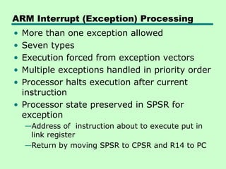
ARM Interrupt (Exception)Processing
• More than one exception allowed
• Seven types
• Execution forced from exception vectors
• Multiple exceptions handled in priority order
• Processor halts execution after current
instruction
• Processor state preserved in SPSR for
exception
—Address of instruction about to execute put in
link register
—Return by moving SPSR to CPSR and R14 to PC
#20 1. The PC contains 300, the address of the first instruction. This instruction (the value 1940 in hexadecimal) is loaded into the instruction register IR, and the PC is incremented. Note that this process involves the use of a memory address register and a memory buffer register. For simplicity, these intermediate registers are ignored. 2. The first 4 bits (first hexadecimal digit) in the IR indicate that the AC is to be loaded. The remaining 12 bits (three hexadecimal digits) specify the address (940) from which data are to be loaded. 3. The next instruction (5941) is fetched from location 301, and the PC is incremented. 4. The old contents of the AC and the contents of location 941 are added, and the result is stored in the AC. 5. The next instruction (2941) is fetched from location 302, and the PC is incremented. 6. The contents of the AC are stored in location 941.
#25 Registers perform two important functions in the CPU operation. They are: 1. Providing a temporary storage area for data. This helps the currently executing programs to have a quick access to the data, if needed. 2. Storing the status of the CPU as well as information about the currently executing program
Example: Address of the next program instruction, signals received from the external devices and error messages, and such other information is stored in the registers.
#32 Program counter (PC): Contains the address of an instruction to be fetched. Instruction register (IR): Contains the instruction most recently fetched. Memory address register (MAR): Contains the address of a location in memory. Memory buffer register (MBR): Contains a word of data to be written to memory or the word most recently read.

![Components of an Instruction Format
•Opcode (Operation Code): Specifies the operation to be performed,
such as ADD, SUB, LOAD, or STORE.
•Operand References: Specifies the data (operands) on which the
operation is to be performed.
•This can be a value, a register, or a memory address.
•Addressing Mode: Specifies how the address of an operand is
determined.
•Visual Element: A simple block diagram showing the main fields of
a generic instruction.
•[ Opcode | Addressing Mode | Operand Address ]](https://image.slidesharecdn.com/chapter-2-251104062146-5f9850c4/85/Chapter-2-The-CPU-Structure-and-Function-Computer-Architecture-and-Organization-40-320.jpg)
![ Direct (or absolute) addressing
• The instruction contains the operand's effective memory address.
• The CPU goes directly to this address to fetch the data.
• Example: LOAD R1, 1000H
• Best for: Accessing static data, such as fixed variables.
Indirect addressing
• The instruction's address field points to a memory location or
register that holds the effective address of the operand.
• Example: ADD R1, [1000H]
• Best for: Implementing pointers, as the pointer's address is
known, but the data it points to can change
Common types of addressing modes](https://image.slidesharecdn.com/chapter-2-251104062146-5f9850c4/85/Chapter-2-The-CPU-Structure-and-Function-Computer-Architecture-and-Organization-45-320.jpg)
![ Register indirect addressing
• Similar to indirect addressing, but the register contains the effective
• address of the operand. This is faster than memory-based indirect
addressing because registers are faster to access.
• Example: LOAD R1, (R2)
• Best for: Implementing pointers and iterating through arrays
Indexed addressing
• The effective address is calculated by adding a constant value
(displacement) to the contents of an index register.
• Example: ADD R1, TABLE1[R2]
• Best for: Efficiently accessing elements in an array or list
Common types of addressing modes](https://image.slidesharecdn.com/chapter-2-251104062146-5f9850c4/85/Chapter-2-The-CPU-Structure-and-Function-Computer-Architecture-and-Organization-46-320.jpg)
![ A subroutine call is implemented with the
following microoperations:
CALL:
SP SP-1
← : Decrement stack point
M[SP] PC
← : Push content of PC onto
the stack
PC←Effective Address : Transfer control
to the subroutine
RETURN:
PC M[SP]
← : Pop stack and transfer to
PC
SP SP+1
← : Increment stack pointer](https://image.slidesharecdn.com/chapter-2-251104062146-5f9850c4/85/Chapter-2-The-CPU-Structure-and-Function-Computer-Architecture-and-Organization-66-320.jpg)
![CPSR
• CPSR process status register
—Exception modes have dedicated SPSR
• 16 msb are user flags
—Condition codes (N,Z,C,V)
—Q – overflow or saturation in some SMID
instructions
—J – Jazelle (8 bit) instructions
—GEE[3:0] SMID use [19:16] as greater than or
equal flag
• 16 lsb system flags for privilege modes
—E – endian
—Interrupt disable
—T – Normal or Thumb instruction
—Mode](https://image.slidesharecdn.com/chapter-2-251104062146-5f9850c4/85/Chapter-2-The-CPU-Structure-and-Function-Computer-Architecture-and-Organization-123-320.jpg)